1
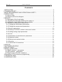
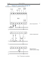
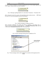
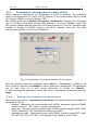
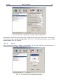
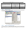
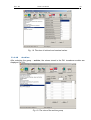
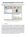
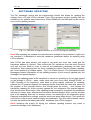
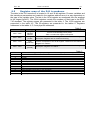
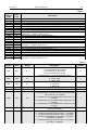
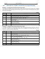
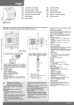
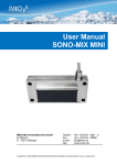
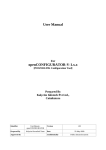
PROGRAMMABLE
TRANSDUCER
OF 1-PHASE POWER
NETWORK PARAMETERS
P41 TYPE
USER’S MANUAL
1
P 41 -0 9
Use r's ma nu a l
2
Contents
1 APPLICATION......................................................................................................................3
2 TRANSDUCER SET.............................................................................................................3
3 BASIC REQUIREMENTS AND OPERATIONAL SAFETY...................................................3
4 INSTALLATION.....................................................................................................................4
4.1 Way of fixing..................................................................................................................4
4.2 External connections diagram.......................................................................................5
5 SERVICE..............................................................................................................................6
5.1 Description of the frontal plate......................................................................................6
5.2 Signaling the state after switching the supply on.........................................................6
5.3 Installation of port COM drivers on a computer............................................................6
5.4 Transducer configuration using LPCon.........................................................................8
5.4.1 Setting the tramsmission parameters .....................................................................8
5.4.2 Setting the measurement parameters ....................................................................9
5.4.3 Archive parameters................................................................................................10
5.4.4 Erasing of counters, extreme values and archive ................................................10
5.4.5 Setting analog output parameters..........................................................................11
5.4.6 Clock......................................................................................................................12
5.4.7 Restoration of manufacturer's parameters ..........................................................13
5.4.8 Measured values ...................................................................................................14
5.4.9 Minimal and maximal values .................................................................................14
5.4.10 Archive.................................................................................................................15
5.4.11 About the P41 transducer ..................................................................................16
6 ARCHIVE............................................................................................................................16
7 SOFTWARE UPDATING....................................................................................................17
8 ERROR CODES ................................................................................................................18
9 SERIAL INTERFACES ......................................................................................................18
9.1 RS485 interface – parameters....................................................................................18
9.2 USB interface – parameters........................................................................................18
9.3 Register map of the P41 transducer ..........................................................................19
10 Examples of P41 transducers programming ...................................................................24
11 TECHNICAL DATA............................................................................................................25
12 ORDERING CODE...........................................................................................................27
P4 1 -09
Use r's m an ua l
3
1 APPLICATION
The P41 transducer is a digital programmable device destined to measure and convert of
1-phase power network.
It enables for measurement and conversion of measured quantities into standarised analog
current signal.
Quantities measured and calculated by the transducer:
⇒
⇒
⇒
⇒
⇒
⇒
⇒
⇒
⇒
⇒
⇒
phase voltage
current
active power
reactive power
apparent power
active power factor
reactive power factor
averaging active power (e.g.15 min.)
Tangens ϕ
active and reactive energy
frequency
U
I
P
Q
S
Pf
tg ϕ
Pav
ϕ
Ept, Eqt,
f
The transducer has an archive that can store up to 9000 values of a quantity selected by
a user, together with time marker. The transducer stores maximal and minimal values for all
measured quantities. Additionally, it is possible to introduce external transmission of
measuring transformers which will be taken into account while measuring and calculating of
all measuring quantities. The update time of all available quantities does not exceed
1 second. All quantities and configuration parameters are available through the RS485
interface and USB.
The transducer output signals are galvanically isolated from input signals and the supply.
Transducer housing is made of plastic. On the external side of the transducer there are
screw terminal strips socket – plug to which wires of a maximal diameter - 2,5 mm 2 can be
connected.
2
TRANSDUCER SET
The transducer set consists of:
- transducer P41
- user's manual
- guarantee card
- CD
3
1 pc
1 pc
1 pc
1 pc
BASIC REQUIREMENTS AND OPERATIONAL
SAFETY.
In the safety service scope, the transducer meets the requirements of the PN-EN 61010-1
standard.
Observations concerning the operational safety:
•
acc. 61010-1
All operations concerning transport, installation and commissioning as well as
maintenance must be carried out by qualified, skilled personnel, and national
regulations for the prevention of accidents must be observed.
P 41 -0 9
Use r's ma nu a l
4
•
Before switching the transducer on, one must check the corectness of connections to
the network.
•
The removal of the transducer casing during the guarantee contract period causes its
cancellation.
•
The transducer is destined to be installed and used in industrial electromagnetic
environment conditions.
•
A switch or a circuit-breaker should be located near the device, easy accessible by
the operator and suitably marked.
4
INSTALLATION
4.1
Way of fixing
The P41 transducer is adapted to be mounted on a 35 mm rail acc.to EN 60715. The overall
dimensions and the way of fixing are presented on the fig. 1.
Fig. 1. Overall dimensions and the way of fixing
P4 1 -09
4.2
Use r's m an ua l
5
External connections diagram
The transducer connection is presented on the fig. 2.
Direct measurement
Indirect
measurement
Fig. 2. Transducer connections
P 41 -0 9
5
5.1
Use r's ma nu a l
6
SERVICE
Description of the frontal plate
transducer state diode
data reception diode through RS485
data transmission diode through RS485
USB
Fig. 3. The view of frontal plate
5.2
Signaling the state after switching the supply on
After switching the supply on, the state diode should light up for a moment in red, and next
should light up in green. The recording confirmation in registers is signaled by a short
extinction of a state diode.The incorrect work is signaled by the state diode in the way
described in the chapter 7. The data reception through the RS485 interface is signaled by
a pulsing of the RxD diode, and the data transmission is signaled by a pulsing of the TxD
diode.
5.3
Installation of port COM drivers on a computer
Before carrying out the transducer configuration, the drivers provided on the attached CD
should be installed. The P41 transducer uses the software, which is created in the system
by the Universal Master Bus device – Przetwornik / P41 Transducer and by a virtual port
Com named Przetwornik/ P41 Transducer attached to it. The installation of a driver in the
Windows system causes adding another serial port Com to the list of ports serviced by the
operational system.
After the transducer has been added to the USB port, the operational system will notify on
the occurrence of a new device by displaying a message presented on the fig. 5. Found
New Wizard of the Universal Serial Bus will activate automatically. The wizard's suggestions
ought to be followed by selecting installation from the indicated localization and giving
a tract for drivers, which can be found on an attached CD. The drivers are compatible with
the following systems: Windows 2000, XP, Server 2003, Vista, Windows 7, Server 2008 (x86
P4 1 -09
Use r's m an ua l
7
and x64). At drivers installation, a message signaling the lack of drivers digital signature can
occur. Ignore it and proceed with further installation.
Fig. 4. Message signaling detection of a new device "Transducer / Transducer P41".
After closing the wizard, the system will immediately detect another device – USB Serial
Port (fig. 6). Found new hardware wizard will be restarted.
Fig. 5. System message on finding new device.
After successful installation, the system will notify on installing a new device (fig. 7).
Two new devices will appear in Device Manager – Transducer/Transducer P41 and Port
COM named: Transducer/Transducer P41, according to fig. 8.
Fig. 6. System message finishing drivers installation of P41.
Properly installed P41
device with assigned
virtual port COM6
Fig. 7. Device manager window with installed P41 transducer with assigned port No.
COM6
P 41 -0 9
5.4
Use r's ma nu a l
8
Transducer configuration using LPCon
LPCon program is destined for the configuration of the P41 transducer. The transducer
ought to be connected to PC using a PD10 converter (if the communication will be carried
out through RS485) or directly through USB.
After selecting the menu Options->Connection configuration, configure the connection
(fig. 8). For direct connections through USB: address 1, baud rate 9600kb/s, mode RTU
8N2, timeout 1000ms and the proper port COM where the driver of the P41 transducer was
installed or through the RS485 interface and PD10: address, baud rate, the mode
in accordance with the ones set in the transducer.
Fig. 8. Configuration of connection with the P41 transducer
After the connection has been configured, select Device -> Transducers -> P41 from the
menu, and then click the icon Readout in order to read out all parameters. The parameters
can be also read out in each group individually by clicking on Refresh.
In order to change the parameters, write a new value in a parameter window and then click
Apply.
5.4.1
Setting the tramsmission parameters
After selecting the group: - transmission parameters, the following items are available for
configuration: (fig. 9):
• address – address for the communication with the P41 transducer within the RS485
interface ranged 1…247. Value 1 is set by manufacturer,
• baud rate – the communication speed within RS485 interface ranged (4800, 9600,
19200, 38400 bit/s). The manufacturer's setting is on 9600,
• transmission mode - transmission mode within RS485 interface ranged (RTU 8N2,
RTU 8E1, RTU 8O1, RTU 8N1). The manufacturer's setting is on RTU 8N2.
P4 1 -09
Use r's m an ua l
9
Fig. 9. The view of configuration window for transmission parameters
5.4.2
Setting the measurement parameters
After selecting the group: - measurement parameters, the following items are available for
configuration (fig. 10):
• transformer current ratio. The multiplier used to convert current on the primary side of
transformer. It is set on 1 by the manufacturer,
• transformer voltage ratio. The multiplier used to convert voltage on the primary side
of transformer. It is set on 1.0 by the manufacturer,
• the method of mean power synchronization:
- a walking window 15 min. – average power PAV will be calculated for the last 15
minutes, updated every 15 seconds, the so called moving window,
- the measurement synchronized with the clock every 15, 30 or 60 minutes - average
power PAV will be updated every 15, 30 or 60 minutes synchronized with internal real
clock (fig. 11).
The manufacturing setting is on a walking window,
Fig. 10. View of configuration window for measurement settings
P 41 -0 9
Use r's ma nu a l
10
Fig. 11. Measurement of mean active power 15 minutes synchronized with the clock
•
•
mean ordered power. Ordered power in percentage of transducer rated power.
the calculate method of reactive energy. The division way of reactive energy
calculation: inductive and capacitive or positive and negative.
5.4.3
Archive parameters
After selecting the group: - archive parameters, the following comments are available to
carry out (fig. 12):
• selection of archive value,
• selection of archive condition,
• setting limits of archive (TL, TH).
Fig. 12. The view of configuration window for archive parameters
5.4.4
Erasing of counters, extreme values and archive
After selecting the group: - erasing of counters, extremes and archive, the following
comments are available to carry out (fig. 13):
• erasing of watt-hour meters - individual or all meters of active and reactive energy are
P 41 -0 9
•
•
•
Use r's ma nu a l
11
erased,
erasing of mean active power,
erasing of min. and max. The actual measured value is prescribed to minimal and
maximum value,
erasing of archive.
Fig. 13. The window of erasing counters, extremes and archive
5.4.5
Setting analog output parameters
After selecting the group: - analog output, the following output parameters are available for
configuration:
• assigning of a parameter to the analog output. The type of signal, to which an output
is to react according to table 1,
• lower value of the input range. The percentage value of a selected signal,
• upper value of the input range. The percentage value of a selected signal,
• lower value of the output range. The value of output signal in mA,
• upper value of the output range. The value of output signal in mA,
• work mode of the analog output. The following modes are available: normal, lower
value, upper value.
• output value in case of input error parameter in mA.
The exemplary configuration of the analog output was presented in the fig. 14.
P 41 -0 9
Use r's ma nu a l
12
Fig. 14. The view of window for analog output configuration
Admissible overflow on the analog output of 20% of the lower and upper value of the range.
The minimum value on the analog output: -20 x 1,2 = -24 mA; the maximum value on the
analog output 20 x 1,2 = 24 mA.
5.4.6
Clock
After selecting the group: - clock it is possible to set the time and date, and synchronize it
with the time on the configuring computer (fig. 15).
Fig. 15. The view of clock configuration window
P4 1 -09
5.4.7
Use r's m an ua l
13
Restoration of manufacturer's parameters
After selecting the group: - restoration of manufacturer's parameters (fig. 16) it is
possible to restore manufacturer's parameters presented in the table 1:
Fig. 16. The window of restoration of manufacturer's parameters
Parameter description
Transformer current ratio
Transformer voltage ratio
Synchronization of mean active
power:
The method of storing the minimal
and maximal values
The method of reactive power
calculation
Ordered power
Quantity on the continuous output
Lower value of the input range in % of
the nominal input range
Upper value of the input range in % of
the nominal input range
Lower value of the output range of the
output
Upper value of the output range of the
Range / Value
1…10000
1.0…4000.0
walking window 15 minute
(write into archive every 15
minutes); measurement
synchronized with the clock
every 15, 30 or 60 minutes
0,1
Table 1
Manufacturer's
value
1
1,0
walking window
0...144,0 %
0…11 (according to table 1)
-144.0 … 144.0 %
0 – no errors
1 - with errors
(1e20, 1e20)
0 – inductive and
capacitive energy
100,0%
3
0.0 %
-144.0 … 144.0 %
100.0 %
-20.00 … 20.00 mA
4.00 mA
0.01 … 20.00 mA
20.00 mA
0,1
P 41 -0 9
Use r's ma nu a l
14
output
Manual switching on of the analog
output
Address in MODBUS network
Transmission mode:
Baud rate:
5.4.8
normal work,
lower value of the output
range,
upper value of the output
range,
1 … 247
8n2, 8e1, 8o1, 8n1
4800, 9600, 19200, 38400
normal work
1
8n2
9600
Measured values
After selecting the group: - measured values, all parameters measured by the transducer
are displayed in the form of the list. (fig. 17).
Fig. 17. Window view for the measured values group
5.4.9
Minimal and maximal values
After selecting the group: - minimal and maximal values, all minimal and maximal values
of individual parameters measured by the transducer are displayed in the form of the list (fig.
18).
P4 1 -09
Use r's m an ua l
15
Fig. 18. The view of minimal and maximal values
5.4.10
Archive
After selecting the group: - archive, the values stored in the P41 transducer archive are
displayed (fig. 19).
Fig. 19. The view of the archive group
P 41 -0 9
5.4.11
Use r's ma nu a l
16
About the P41 transducer
After selecting the group: - about the P41 transducer, the following information is
displayed: picture of the device, serial number, program version and short description of the
device (fig. 20).
Fig. 20. The view of about P41 transducer group
6
ARCHIVE
The direct access to the archive is destined for 15 records containing the date, time and the
value of located in the range addresses 1000 – 1092. The register 1000 is the localization
for the position of the first (the oldest) archived sample, whereas in 1001 is the localization
of the last archived sample (the youngest). The register 1002 contains the value of the first
record of the fifteen available ones located in registers 1003 – 1092. Entering the value of
the first readout record (1 – 9000) causes the data updating of 15 records to readout. In the
registers, to which samples have not been entered yet, there are values 1e20. The archive
is arranged as a circular buffer. After the nine thousandth value has been entered, the next
one overwrites the oldest one numbered 0, the next one another one with the number 1 ,
etc. If the value of the register 1000 is greater than 1001, it means that the buffer has been
overflowed. For example, the value 15 in the register 1000 and 14 in the register 1001
means that there were more than nine thousand samples and that the oldest samples are
from the record 15 to 9000, then from the record 1 to the youngest record numbered 14.
Erasing of mean power or changing the averaging time does not erase the archive.
Automatic file deletion comes with the change of current or voltage ratio.
P4 1 -09
7
Use r's m an ua l
17
SOFTWARE UPDATING
The P41 transducer comes with the implemented function that allows for updating the
software from a PC with LPCon software. Free LPCon program and the updating files are
available on our website www.lumel.com.pl. Either RS485 port and USB port can be used to
carry out the updating process.
a)
b)
Fig. 21. The view of program window: a) LPCon, b) program updating
Note! After updating the software the manufacturer's settings for the transducer ought to be
set, therefore it is advisable to store the transducer parameters before its updating using
LPCon software.
After LPCon has been started, one ought to set serial port, baut rate, mode and the
transducer address in Options. Then choose the P41 transducer from the menu Devices
and click the icon Read in order to read all set parameters (necessary for their later
restoration). After selecting from the menu Updating the option Device software updating,
the Lumel Updater (LU) window opens – Fig. 21 b. Press Connect. The information window
Messages contains information on the updating process. At the correctly opened port, the
message Port opened displays.
Entering the updating mode in the transducer is carried out remotely by LU program (based
on the settings in LPCon - adres, mode, baud rate, port Com) either through RS485 or
USB. Pulsating of the transducer state diode in green signals readiness for updating,
whereas the LU program displays the message Device found and the name and version of
the program of the conneted device. One should press the button ... and indicate the
transducer updating file. At the correctly opened file, the information File opened displays.
One should press Send button. After updating being successfully completed the transducer
switches to normal work, whereas the information window displays Done and the duration
time of the updating. After the LU window closure, one should go to the parameters group
Restoring manufacturer's settings, mark the option and press Apply button. Then press the
icon Save in order to save readout initially set parameters. The up-to-date software version
can also be checked via reading About P41 transducer from LPCon program.
Note! Switching the supply off during the software updating process may result in
permenent damage of the transducer!
P 41 -0 9
8
Use r's ma nu a l
18
ERROR CODES
After connecting the transducer to the network, messages about errors can appear.
Causes of the errors are presented below:
- the state diode pulsates in red – lack of calibration or the non-voliatile memory is
damaged; one must return the transducer to the manufacturer
- the state diode lights in red – inapropriate work parameters; one must configure the
transducer again
9
9.1
•
•
•
•
•
•
SERIAL INTERFACES
RS485 interface – parameters
identifier
transducer address
baud rate
working mode
infomation unit
maximal time of reply
0xAF
1..247
4.8, 9.6, 19.2, 38.4 kbit/s
Modbus RTU
8N2, 8E1, 8O1, 8N1
1000 ms
• maximal number of read out registers in one query
- 56 registers – 4-byte,
- 105 registers – 2-byte,
• implemented functions
03, 06, 16, 17
-03 readout of registers
- 06 write of register
-16 write of registers
-17 device identification
Manufacturer's settings: address 1, baud rate 9600 bauds, working mode RTU 8N2.
9.2
•
•
•
•
•
•
USB interface – parameters
identifier
transducer address
baud rate
working mode
information unit
maximal time of reply
0xAF
1
9.6 kbit/s
Modbus RTU
8N2
800 ms
• maximal number of read out registers in one query
- 56 registers – 4-byte,
• implemented functions
- 105 registers – 2-byte,
- 03, 06, 16, 17
- 03 readout of registers
- 06 write of 1 register
- 16 write of registers
- 17 device identification
P4 1 -09
9.3
Use r's m an ua l
19
Register map of the P41 transducer
The data in the P41 transducer is located in 16 and 32-bit registers. Process variables and
the transducer parameters are located in the registers address area in a way dependent on
the type of the variable value. The bits in the 16-bit register are numbered from the smallest
to the largest (b0-b15). The 32-bit registers contain the numbers of float type in the IEEE745 standard. The register ranges are presented in the table 2. The 16-bit registers are
presented in the table 4,5. The 32-registers are presented in the tables 6. Registers
addresses in the tables 4, 5, 6 are physical addresses.
Table 2
Address range
1000 – 1092
4000 – 4062
Value type
Integer
(16 bits)/
Record
Integer
(16 bits
7000 – 7118
Float
(2x16 bits)
7500 – 7559
Float
(32 bits)
Description
Archive of the avarage power profile.
Table 4 contains the registers description .
The value located in one 16-bit register. Table 5 contains the registers
description. Registers are for readout and writing.
The value located in two consecutive 16-bit registers. The registers
content corresponds to the 32-bit register content from the 7500 area.
Registers for readout.
The value located in one 32-bit register. Table 6 contains the registers
description. Registers for readout.
Table 3
Value
0
1
2
3
4
5
6
7
8
9
10
11
Kind of type of input quantity, to which analog output is to respond
output swithed off
Voltage
Current
Active power
Inactive power
Apparent power
PF factor
tg φ
Frequency
Active average power PAV 15, 30, 60 minute
Current L1/3
Ordered power
P 41 -0 9
Use r's ma nu a l
20
Table 4
Registers
address
16 bit
1000
1001
1002
1003
1004
1005
1006
1007
1008
1009
1010
1011
1012
1013
1014
…
1087
1088
1089
1090
1091
1092
operations
R
R
R/W
R
R
R
R
R
R
R
R
R
R
R
R
…
R
R
R
R
R
R
Description
Position of the oldest archived value
Position of the youngest archived value
First available reecord – NrBL (range 1…9000)
Year of archiving the value numbered NrBL + 0
Month * 100 + day of archiving the value numbered NrBL + 0
Hour * 100 + minute of archiving the value numbered NrBL + 0
Second of archiving the value NRBL + 0
Archived value numbered NrBL + 0
of float type – 4 bytes in order 3-2-1-0
Year of archiving the value numbered NrBL + 1
Month, day of archiving the value numbered NrBL + 1
Hour, minute of archiving the value numbered NrBL + 1
Second of archiving the value NRBL + 1
Archived value of the value numbered NrBL + 1
float type – 4 bytes in order 3-2-1-0
…
Year of archiving the value numbered NrBL + 14
Month, day of archiving the value numbered NrBL + 14
Hour, minute of archiving the value numbered NrBL + 14
Second of archiving the value NRBL + 0
Archived value of the value numbered NrBL + 14
float type – 4 bytes in order 3-2-1-0
Table 5
Adres
rejestru
Operations
Range
4000
RW
0..1
4001
RW
0..1
4002
RW
0..1
4003
4004
RW
RW
1..40000
1..10000
4005
RW
0..3
4006
RW
0..11
4007
RW
0..9
Description
Input synchronization:
0 - synchronization with voltage
(measurement of all values)
1- synchronization with current
(measurement of current and frequency only)
Voltage input range:
0 - range 100V
1- range 400V
Current input range
0 - range 1A
1 - Range 5A
Voltage transformer ratio x 10
Current transformer ratio
Synchronizing of active mean power:
0 - walking window 15 minute (entry synchronized with
the clock every 15 minutes)
1 – measurement synchronized with the clock every 15
minutes,
2 – measurement synchronized with the clock every 30
minutes,
3 – measurement synchronized with the clock every 60
minutes,
Archived quantity
/ code acc.to table3 /
Archiving condition
0 – continous archiving when the value >= reg 4009
1 – continous archiving when the value < reg 4008
2 – continous archiving when the value <= reg 4009
and value >= reg4008
3 – continous archiving when the value >= reg 4009
and value <= reg4008
Default
0
1
1
10
1
0
0
5
P4 1 -09
Use r's m an ua l
4008
4009
4010
4011
RW
RW
RW
RW
4012
RW
4013
RW
4014
RW
4015
RW
4016
RW
4017
4018
4019
4020
4021
4022
4023
4024
4025
4026
4027
RW
RW
RW
RW
RW
RW
RW
RW
RW
RW
RW
4028
RW
4029
RW
4030
RW
4031
RW
4032
RW
4033
RW
4034
RW
4035
RW
4036
4037
RW
RW
4038
RW
4039
RW
4040
4041
4042
4043
RW
RW
RW
RW
4 – continous archiving every 1s
5 – archiving turned off
6 – archiving every 15 minutes synchronized
with RTC
7 – archiving every 30 minutes synchronized
with RTC
8 – archiving every 60 minutes synchronized
with RTC
9 – archiving every time set in reg 4010
0..1440
Lower archiving value
0..1440
Upper archiving value
1...3600
Archiving time
0..65535
reserved
Way to store minimal and maximal value: 0 – no errors,
0,1
1 – with errors
0,1
Zarezerwowane
Way to count reactive energy:
0,1
0 – inductive and capacitive energy
1 – positive and negative energy
Ordered power
0..1440
in [o/oo] of rated input range
Erasing of watt-hour meters:
0…4
0 – no changes, 1- erase active energies,
2 – erase reactive energies, 3 – erase all energies
0,1
Erasing of active mean power PAV
0,1
Erasing archive
0,1
Erasing of min and max
0..65535
reserved
0..65535
reserved
0..65535
reserved
0..65535
reserved
0..65535
reserved
0..65535
reserved
0..65535
reserved
0..65535
reserved
Analog output 1 - quantity on the output
0,1..11
/ code acc. to table 3 /
Analog output 1 - type: 0 – (0...20) mA; 1 – (4…20) mA;
0..2
2 – (-20 ..20) mA
-1440..0..1440 Analog output 1 - lower value of the input range in [ o/oo]
[o/oo]
of rated input range
-1440..0..1440 Analog output 1 - upper value of the input range in [o/oo]
[o/oo]
of rated input range
-2400..0..2400
Analog output 1 - lower value of the current output
[10uA]
range [10 uA]
Analog output 1 - upper value of the current output
1..2400 [10 uA]
range [10 uA]
Analog output 1 - manual switch on:
0..2
0 – normal work, 1 – value set from the register 4032,
2- value set from the register 4033
-2400…2400
Analog output 1 - output value when error
[10uA]
0..65535
reserved
1..247
Address in MODBUS network
Transmission mode: 0->8n2, 1->8e1, 2->8o1,
0..3
3->8n1
transmission baud: 0->4800, 1->9600
0..3
2->19200, 3->38400
0,1
Update the change of transmission parameters
0..59
Seconds
0...2359
Hour *100 + Minutes
101…1231
Month * 100 + day
21
100
100
900
0
1
0
1000
0
0
0
0
3
0
0
1000
0
2000
0
2400
1
0
1
0
0
0
1201
P 41 -0 9
Use r's ma nu a l
4044
RW
2009…2100
4045
RW
0,1
4046
4047
4048
4049
4050
4051
4052
4053
4054
4055
4056
4057
4058
4059
4060
4061
4062
R
R
R
R
R
R
R
R
R
R
R
R
R
R
R
R
R
0..15258
0..65535
0..15258
0..65535
0..15258
0..65535
0..15258
0..65535
0
0
0
0
0..65535
0..65535
0..65535
0..65535
0..65535
Year
Record of standard parameters (with energy reset and
min, max and mean power)
Imported active energy, two smaller bytes
Imported active energy, two larger bytes
Exported active energy, two larger bytes
Exported active energy, two smaller bytes
Reactive inductive energy, two larger bytes
Reactive inductive energy, two smaller bytes
Reactive capacitive energy, two larger bytes
Reactive capacitive energy, two smaller bytes
reserved
reserved
reserved
reserved
Status Register 1 – description below
reserved
Serial number two larger bytes
Serial number two smaller bytes
Program version (* 100)
22
2010
0
0
0
0
0
0
0
0
0
0
0
0
0
-
The brackets [ ] contain correspondingly: resolution or unit.
Energies are available in hundreds of watt-hours (varogodzin) in two 16-bit registers, that is why
while converting the values for the individual energies from registers they ought to be divided by 10
e.g.:
Imported active energy = (reg. value 4089 x 65536 + reg. value 4090) / 10 [kWh]
Exported active energy = (reg. value 4091 x 65536 + reg. value 4092) / 10 [kWh]
Reactive inductive energy = (reg. value 4093 x 65536 + reg. value 4094) / 10 [kVarh]
Reactive capacitive energy = (reg. value 4095 x 65536 + reg. value 4096) / 10 [kVarh]
Status Register 1:
Bit 14 - „1” - lack of calibration or calibration
Bit 7 - „1” - the interval of power averaging did
error
elapsed
Bit 13 - „1” - parameters value error
Bit 6 - „1” - voltage too low to measure frequency
Bit 12 - „1” - energy value error
Bit 5 - reserved
Bit 11 - reserved
Bit 4 - reserved
Bit 10 - reserved
Bit 3 - reserved
Bit 9 - reserved
Bit 2 - „1” - capacity character maximum
Bit 8 - reserved
Bit 1 - „1” - capacity character minimum
Bit 0 - „1” - capacity chracter Q
Table 6
Register Register Opeaddress address ratio
Description
32 bit
16 bit
ns
7000
7500
R
Voltage U
7002
7501
R
Current I
7004
7502
R
Active power P
7006
7503
R
Reactive power Q
7008
7504
R
Apparent power S
7010
7505
R
Współczynnik mocy czynnej
7012
7506
R
Active power to reactive power ratio
7014
7507
R
Frequency
7016
7508
R
Mean active power PAV 15, 30, 60 minute
7018
7509
R
reserved
7020
7510
R
reserved
7022
7511
R
Cosine angle between U and I
7024
7512
R
Angle between U and I
7026
Imported active energy (number of register overflow 7513, reset
7513
R
after exceeding 99999999,9 kWh)
Unit
V
A
W
Var
VA
Hz
PAV
°
100 MWh
P4 1 -09
Use r's m an ua l
7028
7030
7514
R
7515
R
7032
7034
7516
R
7517
R
7518
R
7519
R
7520
R
7521
7522
7523
7524
7525
7526
7527
7528
7529
7530
7531
7532
7533
7534
7535
7536
7537
7538
7539
7540
7541
7542
7543
7544
7545
7546
7547
7548
7549
7550
7551
7552
7553
7554
7555
7556
7557
7558
7559
R
R
R
R
R
R
R
R
R
R
R
R
R
R
R
R
R
R
R
R
R
R
R
R
R
R
R
R
R
R
R
R
R
R
R
R
R
R
R
7036
7038
7040
7042
7044
7046
7048
7050
7052
7054
7056
7058
7060
7062
7064
7066
7068
7070
7072
7074
7076
7078
7080
7082
7084
7086
7088
7090
7092
7094
7096
7098
7100
7102
7104
7106
7108
7110
7112
7114
7116
7118
Imported active energy (countdown counter up to 99999,9 kWh)
Exported active energy (number of register overflows 7515,
reset after exceeding 99999999,9 kWh)
Exported active energy (countdown counter up to 99999,9 kWh)
Reactive inductive energy ( number of register overflows 7517,
reset after exceeding 99999999,9 kVarh)
Reactive inductive energy (countdown counter up to 99999,9
kVarh)
Reactive capacitive energy ( number of register overflows 7519,
reset after exceeding 99999999,9 kVarh)
Reactive capacitive energy ( countdown counter up to 99999,9
kVarh)
reserved
reserved
reserved
reserved
Time - seconds
Time – hours, minutes
Date – month, day
Date - year
Steering of analog output
Ordered power used
Current/ 3
Status 1
Status 2
Voltage min
Voltage max
Current min
Currentmax
Active power min
Active power max
Reactive power min
Reactive power max
Apparent power min
Apparent power max
Power factor (PF) min
Power factor (PF) max
Reactive power to active power ratio min
Reactive power to active power ratio
Frequency min
Frequency max
Active mean power 15, 30, 60 minute min
Active mean power 15, 30, 60 minute max
reserved
reserved
reserved
reserved
Cosine of the angle between U and I min
Cosine of the angle between U and I max
Angle between U and I min
Angle between U and I max
23
kWh
100 MWh
kWh
100 Mvarh
kvarh
100 Mvarh
kvarh
sek
mA
%
A
V
V
A
A
W
W
var
var
VA
VA
Hz
Hz
W
W
°
°
In case of lower overflow the value -1e20 is entered, whereas at upper overflow or error occurence
the value 1e20 is entered.
P 41 -0 9
10
Use r's ma nu a l
24
Examples of P41 transducers programming
Example 1. Programming of unidirectional analog output
To program the operation of the analog output in such a way that input current values 4A correspond
to the value 20 mA of the analog output, whereas input current value 0 A corresponds to the value 4
mA of the analog output.
Table 7
Register
4028
4029
Value
Meaning
2
0
4030
800
4031
400
4032
2000
4033
4034
0
24
current (I)
0 – 0,0 % (percentage value with one decimal place multiplied by 10) lower value of
rated three-phase mean current, (0 A / 5 A ) x 1000 = 0
800 – 80,0 % (percentage value with one decimal place multiplied by 10) upper
value of rated current, (4 A / 5A ) x 1000 = 800
400 – 4,00 mA (value in mA with two decimal places multiplied by 1000) lower value
of current output,
(4,00 mA x 100) = 400
2000 – 20,00 mA (value in mA with two decimal places multiplied by 1000) upper
value of current output,
(20,00 mA x 100) = 2000
0 – normal mode of an analog output
24 – 24 mA on a continuous output when error (-1e20 lub 1e20)
Example 2. Programming of bidirectional analog output
To program the operation of the analog output in such a way, that at the power value 4 A x 230 V x
cos (180°) = -2760 W on the output was the value -20 mA, whwreas for the power value 4 A x 230 V
x cos (0°) = 2760 W was the value 20 mA.
Table 8
Register
4028
4029
Value
4030
800
4031
-2000
4032
2000
4033
4034
0
24
3
-800
Meaning
power (P)
-100 – 100,0 % (percentage value with one decimal place multiplied by 10) lower
value of rated power,
(4 A x 230 V x cos(180°) /5 A x 230 V) x 1000 = - 800
1000 – 100,0 % (percentage value with one decimal place multiplied by 10) upper
value of three-phase rated power,
( 4 A x 230 V x cos(0°) /5 A x 230 V) x 1000 = 800
-2000 – -20,00 mA (value in mA with two decimal places multiplied by 1000) lower
value of current output,
(-20,00 mA x 100) = -2000
2000 – 20,00 mA (value in mA with two decimal places multiplied by 1000) upper
value of current output,
(20,00 mA x 100) = 2000
0 – normal mode of an analog output 1
24 – 24 mA on continuous output 1 when error (-1e20 lub 1e20)
P4 1 -09
11
Use r's m an ua l
25
TECHNICAL DATA
Measuring ranges and admissible basic errors (table 9)
Table 9
Measured
quantity
Current In
Measuring range
1A
0.005 .. 1.200 A~
5A
0.025 .. 6.000 A~
Processing
error
±0.2 %
Voltage L-N
100 V
0.5 .. 120 V
400 V
2 .. 480 V
±0.2 %
45.0 .. 66.0 .. 100 Hz
±0.2 %
-2.88 kW ..1.40 W .. 2.88 kW
±0.5 %
Reactive power
-2.88 kvar ..1.40 var .. 2.88
kvar
±0.5 %
Apparent power
1.40 VA .. 2.88 kVA
±0.5 %
-1 .. 0 .. 1
±0.5 %
-1.2 .. 0 .. 1.2
±1 %
0 .. 359
±1 %
0 .. 9 999 999.9 kWh
±0.5 %
0 .. 9 999 999.9 kvarh
±0.5 %
Frequency
Active power
PF factor
Tangens ϕi
ϕ
Active energy
Reactive energy
Standard conversion time:
Maximal conversion time:
Power consumption:
- in supply circuit
- in voltage circuit
- in current circuit
1.2 s
2.2 s
≤ 3 VA
≤ 0.05 VA
≤ 0.05 VA
Analog output
programmable output:
current (max. range) -24..0..+24 mA
termination resistance of
current output
Robc: 0..250 Ω
voltage: 15V
Serial interfaces
RS485: address 1..247;
mode: 8N2, 8E1, 8O1,8N1;
baud rate: 4.8, 9.6, 19.2, 38.4 kbit/s,
USB: 1.1 / 2.0, address 1; mode 8N2;
baud rate 9.6 kbit/s,
transmission protocol:
response time: 1000 ms
modbus RTU
P 41 -0 9
Use r's ma nu a l
26
Ratio of the Voltage transformer Ku
0,1 .. 4000,0
Ratio of the Current transformer Ki
1 .. 10000
Protection degree ensured by the housing:
for the housing
for terminals
Mass
IP 40
IP 10
0.2 kg
Dimensions
40 x 120 x 100 mm
Fixing Way
on a 35 mm DIN rail
Reference and rated operating conditions.
- supply voltage
85..253 V a.c. 40..400 Hz; 90..300 V d.c.
20..40 V a.c. 40..400 Hz; 20..60 V d.c.
- input signal
0 .. 0.005..1.2 In; 0.05..1.2 Un
for current and voltage
0 .. 0.1..1.2 In; 0..0.1..1.2 Un
for power factors Pfi ,tϕi
frequency 45..66..100 Hz
sinusoidal (THD ≤ 8%)
- power factor
- analog output
-1 .. 0 .. 1
-24 .. -20 .. 0 .. +20..24 mA
- ambient temperature
-10 .. 23 .. +55 °C
- storage temperature
- 30 .. +70 °C
- humidity
< 95% (condensation inadmissible)
- admissible peak factor :
- current intensity
- voltage
- external magnetic field
- short duration overload (5 s)
voltage input
current input
- work position
- warm-up time
2
2
0..40 ..400 A/m
2Un (max.1000 V)
10 In
any
5 min.
Additional errors:
in % of a basic error
- from frequency of input signals
< 50%
- from ambient temperature changes
- for THD > 8%
< 50 % / 10 °C
< 100 %
P4 1 -09
Use r's m an ua l
27
Standards fulfilled by the transducer
- Electrical measuring transducers for converting electrical quantities of alternating
current into analog or digital signals EN 60688:2004
Electromagnetic compatibility:
- noise immunity acc. to EN 61000-6-2
- noise emission acc. to EN 61000-6-4
Safety requirements:
according to EN 61010-1
• isolation between circuits: basic,
• installation category III,
• pollution level 2,
• maximal phase-to-earth voltage:
- for supply and measurement circuits 300 V
- for other circuits 50 V
• altitude above the sea level < 2000 m,
12
ORDERING CODE
Table 10
P41 transducer
Supply:
85..253 V a.c. 40..400 Hz; 90..300 V d.c.
20..40 V a.c. 40..400 Hz; 20..60 V d.c.
Version:
standard
custom-made*
Language:
Polish
English
other
Acceptance tests:
without extra quality requirements
with an extra quality inspection certificate
acc. to customer's requirements*
* after agreeing with the manufacturer
X
XX
X
X
1
2
00
XX
P
E
X
0
1
X
EXAMPLES OF ORDERS:
The code P41-100P0 means the transducer with supplay voltage 85..253 V a.c.; 90..300 V
d.c. Standard version, user's manual in Polish, without extra quality requirements.
tel.: (48-68) 45 75 100 (exchange)
fax: (48-68) 45 75 508
e-mail: [email protected]
http://www.lumel.com.pl
24
Export Department:
Tel.: (48-68) 329 53 02 or 53 04
Fax: (48-68) 325 40 91
e-mail: [email protected]
P41-09
“LUMEL” S.A.
ul. Słubicka 1
65-127 Zielona Góra - Poland