1
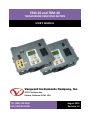
TRM-20 and TRM-40
TRANSFORMER RESISTANCE METERS
USER’S MANUAL
Vanguard Instruments Company, Inc.
1520 S. Hellman Ave.
Ontario, California 91761, USA
TEL: (909) 923-9390
FAX: (909) 923-9391
August 2015
Revision 1.3
TRM-20 AND TRM-40 USER’S MANUAL
REV 1
SAFETY SUMMARY
NOTICE
This manual applies to both the TRM-20 and TRM-40 transformer resistance meters. The
operating procedures are virtually the same for both models, and any differences are clearly
described where applicable.
FOLLOW EXACT OPERATING PROCEDURES
Any deviation from the procedures described in this User’s Manual may create one or more
safety hazards, may damage the TRM-20/40, damage the test transformer, or cause errors in
the test results. Vanguard Instruments Company, Inc. assumes no liability for unsafe or
improper use of the TRM-20/40.
All safety precautions provided in this manual must be observed during all phases of testing
including test preparation, test lead connection, actual testing, and test lead disconnection.
SAFETY WARNING AND CAUTIONS
The TRM-20/40 shall be used only by trained operators. All transformers under test shall be
off-line and fully isolated.
DO NOT MODIFY TEST EQUIPMENT
To avoid the risk of introducing additional or unknown hazards, do not install substitute parts or
perform any unauthorized modification to any TRM-20/40 test unit. To ensure that all designed
safety features are maintained, it is highly recommended that repairs be performed only by
Vanguard Instruments Company factory personnel or by an authorized repair service provider.
Unauthorized modifications can cause safety hazards and will void the manufacturer’s
warranty.
WARNING
Do not remove test leads during a test. Failure to heed this warning can result in electrical
shock to personnel and damage to the equipment.
i
REV 1
TRM-20 AND TRM-40 USER’S MANUAL
TABLE OF CONTENTS
CONVENTIONS USED IN THIS DOCUMENT ..................................................................................... 1
1.0 INTRODUCTION .................................................................................................................... 2
1.1 General Description and Features ................................................................................... 2
1.2 Technical Specifications ................................................................................................... 4
1.3 TRM Controls and Indicators ........................................................................................... 5
2.0 PRE-TEST SETUP ................................................................................................................... 6
2.1 Operating Voltages .......................................................................................................... 6
2.2 LCD Screen Contrast Control............................................................................................ 6
2.3 Printer Paper Control ....................................................................................................... 6
2.4 Printer Paper .................................................................................................................... 6
2.5 Replacing the Thermal Printer Paper............................................................................... 7
3.0 OPERATING PROCEDURES ................................................................................................... 8
3.1 Configuring the LTCA Software for use with the TRM ..................................................... 8
3.2 Connecting the TRM to a PC via Bluetooth ................................................................... 10
3.3 Typical Connections to a Load Tap Changer (LTC) ......................................................... 17
3.4 Typical TRM-20/40 Cable Connections .......................................................................... 17
3.5 General Procedures ....................................................................................................... 19
3.6 Entering Test Record Header Information..................................................................... 20
3.7 Setting the Date and Time ............................................................................................. 24
3.8 Setting the Interface Language ...................................................................................... 25
3.9 Performing a Resistance Test......................................................................................... 26
3.10 Performing a Load Tap Changer / Voltage Regulator Resistance Test .......................... 35
3.11 Performing a Special Resistance Test ............................................................................ 44
3.12 Performing a Dynamic LTC Test ..................................................................................... 51
3.13 Performing a Diagnostic Test ......................................................................................... 56
3.14 Demagnetizing the Transformer Core ........................................................................... 58
3.15 Working with Test Records ............................................................................................ 60
3.15.1. Viewing the Contents of the Working Memory ..................................................... 60
3.15.2. Saving Test Results to a Test Record ...................................................................... 62
3.15.3. Restoring a Test Record From Flash EEPROM ........................................................ 64
3.15.4. Restoring a Test Record From a USB Flash Drive ................................................... 68
3.15.5. Copying Test Records to a USB Flash Drive ............................................................ 70
3.15.6. Printing a Test Record Directory ............................................................................ 73
3.15.7. Erasing Test Records from the Flash EEPROM ....................................................... 75
3.16 Erasing Test Records from a USB Flash Drive ................................................................ 78
3.17 Converting Resistance Measurements .......................................................................... 81
ii
TRM-20 AND TRM-40 USER’S MANUAL
REV 1
LIST OF FIGURES
Figure 1. TRM-20/40 Controls and Indicators ................................................................................ 5
Figure 2. Typical Connections to a Load Tap Changer (LTC) ......................................................... 17
Figure 3. Typical TRM Connections Diagram for A Dynamic Resistance Test .............................. 17
Figure 4. Typical TRM Connections Diagram for 2 Windings........................................................ 18
Figure 5. Typical Resistance Test Results Printout........................................................................ 34
Figure 6. Typical LTC/Voltage Regulator Test Report Printout ..................................................... 43
Figure 7. Typical Special Test Report Printout .............................................................................. 50
Figure 8. Typical Dynamic LTC Test Results Printout Showing an Opened Circuit ....................... 55
Figure 9. Typical Test Record Directory Printout .......................................................................... 74
LIST OF TABLES
Table 1. TRM-20/40 Technical Specifications ................................................................................. 4
iii
REV 1
T
TRM-20
AND
D TRM-40 USER’S
U
MANUAL
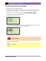
CONVE
ENTIONS
S USED IN
N THIS DO
OCUMEN
NT
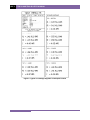
This docu
ument uses the followin
ng conventio
ons:
•
Both the TRM-20
0 and TRM-4
40 are simplyy referred to
o as “TRM” in
n this manuaal. The exactt
modeel number iss used only in
n cases where differences between the units arre discussed..
•
A keyy, switch, or knob on thee TRM is indiicated as [K
KEY], [SWIT
TCH], [KNOB].
•
Menu
u names are
e referenced as “MENU NAME”
N
•
TRM LCD screen output is shown as:
1.
2.
3.
4.
5.
•
1
2
3
4
5
When
n instruction
ns are provid
ded, the men
nu item thatt should be selected
s
is printed in bold as
show
wn below (op
ption 3 should be selecteed in this exaample):
1.
2.
3.
4.
5.
•
OPTION
OPTION
OPTION
OPTION
OPTION
OPTION
OPTION
OPTION
OPTION
OPTION
1
2
3
4
5
Warn
ning message
es are indicaated as:
Waarning messsage
WA
ARNING
•
Impo
ortant notes are indicateed as:
Note details
NOTE
1
TRM-20 AND TRM-40 USER’S MANUAL
1.0
INTRODUCTION
1.1
General Description and Features
REV 1
The TRM-20 and TRM-40 are Vanguard Instruments’ third generation transformer winding
resistance meters. The TRM line is designed specifically to measure DC resistance values of
transformer windings, rotating machine windings, or any dc resistance of an inductive device.
The TRM line features dual resistance-reading input channels that can measure two winding
resistances simultaneously (primary and secondary windings of a transformer).
Both the TRM-20 and TRM-40 can provide a fast and stable reading of very large transformers
by utilizing a 60Vdc power supply. The TRM-20 is capable of outputting a selectable test current
from 1A to 20A while the TRM-40’s test current is selectable from 1A to 40A.
Since the TRM-20 and TRM-40 can accurately measure resistance values from 1 micro-ohm to
2,000 Ohms, they can be used as micro-ohm meters to measure EHV circuit breaker contact
resistance, or for any low resistance measuring application.
If the transformer winding resistance temperature is available at the time of testing, the TRM
can calculate the equivalent resistance value at any temperature value. This useful feature
allows the user to compare the field readings against the factory test resistance values.
A special test mode allows the TRM to collect data automatically for up to 90minutes (at 60second sampling interval) or 45 minutes (at 30 second sampling interval). Test data is recorded
with a time stamp.
All test results can be printed on a 2.5” wide thermal printer. Test record header information
including the company, substation name, transformer information can also be entered using
the 16-key key pad.
The TRM-20 and TRM-40 can also demagnetize the inductive device under test, eliminating the
manual task of demagnetizing the transformer core after a resistance test.
The TRM also has a “make-before-break” test mode that can be used to test the load tap
changer (LTC) or voltage regulator test sequence. The TRM produces a “Dynamic-Resistance”
graph of the LTC or voltage regulator contact under operation. An opened contact can be
detected visually from this resistance chart.
The TRM’s built-in LTC/Voltage regulator can be used to change the LTC/Voltage regulator tap
position from the TRM front panel.
Safety Features
The TRM automatically dissipates the energy stored in the transformer at the end of each test.
The discharge circuit will continue to work even if the TRM power supply is lost.
Test Record Storage
The TRM can store up to 100 test records internally. For external test record storage, the TRM
features a USB Flash drive interface port. Up to 999 test records can be stored on a connected
USB Flash drive.
2
REV 1
TRM-20 AND TRM-40 USER’S MANUAL
User Interface
The TRM features a back-lit graphic LCD screen (124x64) that is clearly viewable in both bright
sunlight and low-light levels. An alpha-numeric keypad is used to enter test information and to
operate the unit.
Computer Interfaces
The TRM can be connected to a PC via the unit’s RS-232C, USB, or Bluetooth interface. A PC can
be used to retrieve test records (stored in the TRM or USB Flash drive) or to run tests using the
provided software. Test records are automatically exported to PDF, Excel, and XML formats.
3
TRM-20
0 AND TRM-40 USER’S MANUAL
M
1.2
R 1
REV
T
Technical
Specificatio
S
ons
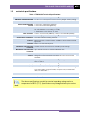
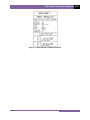
Table 1. TRM-20/40 Technical Specification
ns
TYPE
PH
HYSICAL SPEC
CIFICATIONS
Portable transformer windin
ng resistance meter
m
21” W x 17” H x 9” D (53 cm
m x 43 cm x 24 cm); Weight: 33
3 lbs (15.4Kg))
OPERATIN
NG VOLTAGE 100-240 Vac, 50/60 Hz
RESISTANC
CE READING
RANGE
ACCURACY
1 micro-ohm – 2000 Ohms (TRM-20);
1 micro-ohm to 500 Ohms (TRM-40)
(
1 – 19,999 micro-ohms:
m
±0..5% reading, ±1 count;
20 – 999 milliohms: ±1% reading, ±1 coun
nt;
1 -2000 Ohm
ms: ±1.5% reading, ±1 count
TES
ST CURRENT
1-20A in 1A increments (TR
RM-20); 1-40A in 1A incremen
nts (TRM40)
TES
ST VOLTAGE
60Vdc charging, 18V DC max
m during mea
asurement
RESISTANCE
E CHANNELS
DISPLAY
Two static resistance readin
ng channels
Back-lit LCD (64 x 128 dot graphic),
g
viewa
able in direct su
unlight and low
w
light levels
PRINTER Built-in 2.5” wide
w
thermal prrinter
I
INTERNAL
TE
EST RECORD
STORAGE
E
EXTERNAL
TE
EST RECORD
STORAGE
COMPUTER IN
NTERFACES
100 test reco
ords. Each reco
ord can contain
n up to 99 readings.
Up to 999 tesst records on external
e
USB Fllash drive.
RS-232C, US
SB, and Blueto
ooth
SAFETY Designed to meet UL 61010
0A-1 and Can/CSA C22.2 No
o 1010.1092
standards
EN
NVIRONMENT
HUM
MIDITY (MAX)
Operating: -10˚C to 50˚ C (1
15˚F to +122˚ F);
F Storage: -30
0˚ C to 70˚ C (-22˚F to +158˚ F)
90% RH @ 40°
4 C (104° F) non-condensin
ng
ALTIITUDE (MAX) 2000m (6562
2 ft) to full safetty specification
ns
CABLES
One 50-foot current
c
cable set,
s two 50-foott resistance sen
nse cable set, one
LTC control cable,
c
one grou
und cable, one power cord, One
O RS-232C
cable, one US
SB cable
OPTIONS Transportatio
on Case
WARRANTY
One year on parts and labo
or
The above
a
specifications are valid at nom
minal operatting voltage and
a at a
temp
perature of 25°C
2
(77°F). Specification
ns may chan
nge without prior notice.
NOTE
4
REV 1
1.3
TRM-20 AND TRM-40 USER’S MANUAL
TRM Controls and Indicators
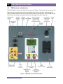
The TRM-20/40’s controls and indicators are shown in Figure 1. The purpose of the controls and
indicators may seem obvious, but users should become familiar with them before using the
TRM. Accidental misuse of the controls will usually cause no serious harm. Users should also be
familiar with the safety summary found on the front page of this User’s Manual.
Figure 1. TRM-20/40 Controls and Indicators
5
TRM-20 AND TRM-40 USER’S MANUAL
2.0
PRE-TEST SETUP
2.1
Operating Voltages
REV 1
The TRM’s operating voltages are 90-240 Vac, 50/60 Hz.
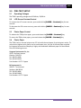
2.2
LCD Screen Contrast Control
To increase the LCD screen contrast, press and hold the [PAPER ∧ Contrast] key for two
seconds.
To decrease the LCD screen contrast, press and hold the [PAPER ∨ Contrast] key for two
seconds.
2.3
Printer Paper Control
To advance the TRM printer paper, press and release the [PAPER ∧ Contrast] key.
To retract the TRM printer paper, press and release the [PAPER ∨ Contrast] key.
2.4
Printer Paper
The TRM’s built-in thermal printer uses 2.5-inch wide thermal paper for printing test results. To
maintain the highest print quality and to avoid paper jams, the use of thermal paper supplied
by Vanguard Instruments Company is highly recommended. Additional paper can be ordered
from the following sources:
Vanguard Instruments Co, Inc.
1520 S. Hellman Avenue
Ontario, CA 91761
Tel: 909-923-9390
Fax: 909-923-9391
Part Number: VIC TP-3 paper
BG Instrument Co.
13607 E. Trent Avenue
Spokane, WA 99216
Tel: 509-893-9881
Fax: 509-893-9803
Part Number: VIC TP-3 paper
6
REV 1
2.5
T
TRM-20
AND
D TRM-40 USER’S
U
MANUAL
R
Replacing
the
t Therma
al Printer Paper
P
The roll of
o thermal paper is houssed inside a dispenser un
nderneath the printer co
over. To replace
the papeer, follow the
e steps below
w:
•
•
•
•
•
•
•
Unscrew the two large prrinter cover screws and remove the printer coveer.
U
Remove the leftover therrmal paper roll
r from thee paper holder.
U
Unroll
the new thermal paper
p
roll.
Feeed the therrmal paper into the slot between the paper poccket and the rubber rolleer.
The printer will
w automatically pull thee paper under the therm
mal head.
Place the pap
per roll into the
t paper ho
older.
Liift the therm
mal head and
d align the th
hermal papeer if necessary.
Re-install the
e printer coveer.
NOTE
Thermal paper has a chemical co
oating on on
ne side of thee paper. This side should
d be
facing th
he thermal print head. In
ncorrect pap
per loading may
m result in
n blank output on
the therm
mal paper.
The therrmal paper will
w show a reed stripe to indicate that the roll is about
a
to run
n out
of paper.
7
TRM-20 AND TRM-40 USER’S MANUAL
3.0
OPERATING PROCEDURES
3.1
Configuring the LTCA Software for use with the TRM
REV 1
The TRM can be used with a PC using the Vanguard LTCA software. Follow the steps below to
properly connect the TRM and configure the LTCA application to recognize the unit.
a. Install the LTCA software (please see the LTCA software user’s manual for details).
b. Connect the TRM to the PC by connecting a USB cable from an open USB port on the PC
to the unit’s “USB PC” port.
c. Turn on the power on the TRM.
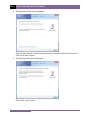
d. If this is the first time you are connecting the unit to the PC, Windows will recognize it as
a new device and automatically install necessary drivers. If using Windows XP, you may
be prompted to install drivers. Select the automatic installation option and Windows will
locate the generic drivers necessary.
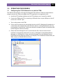
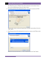
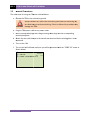
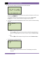
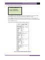
e. Please note that although the unit is connected via USB, it uses an internal serial
interface to communicate with the PC. As such, it will appear in the windows Device
Manager as a USB Serial Port. Open the Device Manager from the Windows Control
Panel and note the COM port number. For example, in the installation shown below, the
TRM is shown as COM10 (USB Serial Port).
8
REV 1
TRM-20 AND TRM-40 USER’S MANUAL
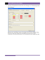
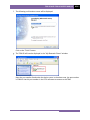
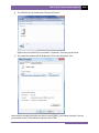
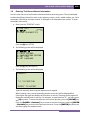
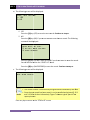
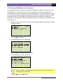
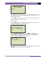
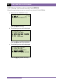
f. Launch the LTCA application and then click on the “Settings” icon. The following window
will be displayed:
Make sure the “Use USB Port” option is UN-checked. Then, from the “COM Port” dropdown menu, select the COM port that corresponds to the port that the TRM is
connected to. Then click the OK button. The LTCA software will now recognize the TRM.
9
TRM-20 AND TRM-40 USER’S MANUAL
3.2
REV 1
Connecting the TRM to a PC via Bluetooth
The TRM can also be connected wirelessly to a PC using Bluetooth. To connect the unit via
Bluetooth, it must first be paired with the PC. Follow the steps below to pair the TRM to a PC
via Bluetooth:
For Windows XP:
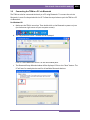
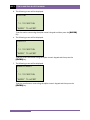
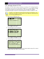
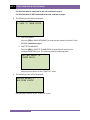
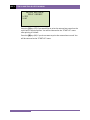
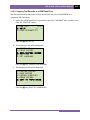
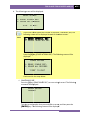
a. Make sure the TRM is turned on. Then double click on the Bluetooth system tray icon
(on the bottom right corner of your computer screen):
b. The “My Bluetooth Places” window will be displayed:
Click on “Add a Bluetooth Device” on the left window pane.
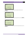
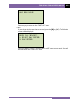
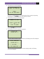
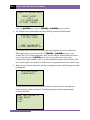
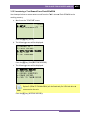
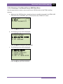
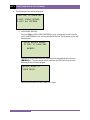
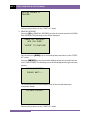
c. The Bluetooth Setup Wizard window will be displayed. Click on the “Next” button. The
PC will scan for nearby devices and list all available Bluetooth devices:
10
REV 1
TRM-20 AND TRM-40 USER’S MANUAL
The TRM will be listed as “TRM S/N” where S/N is the device’s serial number. Click on
the icon for the TRM and then click on the “Next” button.
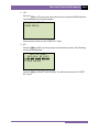
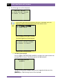
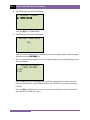
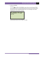
d. The following window will be displayed asking for a secret key to connect to the TRM:
Type the word “default” (without the quotes and in all lower-case) and then click on the
“Next” button.
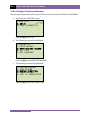
e. The following window will be displayed with the option to connect to the TRM as a serial
port:
Make sure to check the box next to “AT Serial” and then click on the “Next” button.
11
TRM-20 AND TRM-40 USER’S MANUAL
REV 1
f. The following confirmation screen will be displayed:
Click on the “Finish” button.
g. The TRM-20 will now be displayed in the “My Bluetooth Places” window:
Note the port number listed under the device name. In the above case, the port number
is COM14. Use this port number in the LTCA software to connect to the TRM.
12
REV 1
TRM-20 AND TRM-40 USER’S MANUAL
For Windows 7:
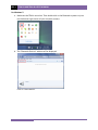
a. Make sure the TRM is turned on. Then double click on the Bluetooth system tray icon
(on the bottom right corner of your computer screen):
b. The “Bluetooth Devices” window will be displayed:
Click on “Add a device”.
13
TRM-20 AND TRM-40 USER’S MANUAL
REV 1
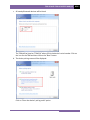
c. All nearby Bluetooth devices will be listed:
The TRM will be listed as “TRM S/N” where S/N is the device’s serial number. Click on
the icon for the TRM and then click on the “Next” button.
d. The device pairing screen will be displayed:
Click on “Enter the device’s pairing code” option.
14
REV 1
TRM-20 AND TRM-40 USER’S MANUAL
e. The following window will be displayed:
Type the word “default” (without the quotes and in all lower-case) in the text box and
click on the “Next” button.
f. The following screen will be displayed:
Click on the “Close” button.
15
TRM-20 AND TRM-40 USER’S MANUAL
REV 1
g. The TRM will now be listed under “Bluetooth Devices”:
Right click on the TRM-20 icon and select “Properties” from the pop-up menu.
h. The properties window will be displayed. Click on the “Hardware” tab:
Note the port number listed after the device name (COM23 in the above example). Use this
port number in the LTCA software to connect to the TRM.
16
REV 1
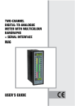
3.3
T
TRM-20
AND
D TRM-40 USER’S
U
MANUAL
T
Typical
Con
nnections to a Load Tap
T Chang
ger (LTC)
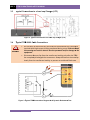
Figure 2. Typiical Connecttions to a Loa
ad Tap Chan
nger (LTC)
3.4
T
Typical
TRM
M-20/40 Ca
able Conne
ections
•
Do not touch or disconneect any test lead
l
that is connected
c
to
o a transform
mer
te
erminal while high curreent is being conducted
c
during a test.. Failure to heed
h
th
his warning can result in
n electric shock to perso
onnel and/o
or damage to
o the
eq
quipment.
•
Disconnect th
he test clips from the traansformer bushing only after the TR
RM
has completeely dischargeed the transfformer. Alwaays disconneect the test clips
c
slowly from the transform
mer bushing to prevent an accidentaal flash-overr.
WARNIN
NGS
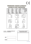
Figure 3. Typical
T
TRM
M Connection
ns Diagram fo
or A Dynamic Resistance
e Test
17
TRM-20 AND TRM-40 USER’S MANUAL
REV 1
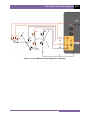
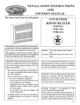
Figure 4. Typical TRM Connections Diagram for 2 Windings
18
REV 1
3.5
T
TRM-20
AND
D TRM-40 USER’S
U
MANUAL
G
General
Pro
ocedures
The main
n steps for using the TRM
M are outlineed below:
a. Ground
G
the TRM
T
to the substation grround.
W
WARNING
Always
A
conn
nect the TRM
M to the subsstation ground before co
onnecting an
ny
test
t lead to any
a transforrmer bushingg. Failure to follow this procedure
p
m
may
damage
d
the TRM.
b. Plug the TRM
M power cablle into a pow
wer outlet.
c. In
nsert currentt-cable plugss and voltagge-sensing caable plugs in
nto the correesponding
co
ontrol panell jacks.
d. A
Attach the test cable clam
mps to the trransformer terminal
t
forr the windingg that is to be
b
m
measured.
e. Turn on the TRM.
T
s
e, and then you will be presented
p
w the “STA
with
ART-UP” men
nu as
f. The unit will self-calibrate
sh
hown below
w:
11/01/1
11
1. RUN TEST
T
09:06:2
21
2. SETUP
P
22°C
72°°F
3. USER DIAGNOST
TICS
19
TRM-20 AND TRM-40 USER’S MANUAL
3.6
REV 1
Entering Test Record Header Information
You can enter the test record header information before performing tests. The record header
includes identifying information such as the company, station, circuit, model number, etc. Once
the header information has been entered, it will apply to all subsequent test records. To enter
the header information:
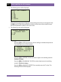
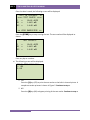
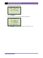
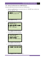
a. Start from the “START-UP” menu:
11/01/11
1. RUN TEST
09:06:21
2. SETUP
22°C
72°F
3. USER DIAGNOSTICS
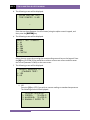
Press the [2] key (SETUP).
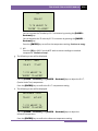
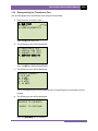
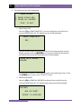
b. The following screen will be displayed:
1. RECORD ID
2. PRINT RECORD
3. SAVE/RESTORE RECORD
4. SET TIME
5. SET LANGUAGE
Press the [1] key (RECORD ID).
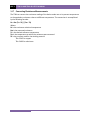
c. The following screen will be displayed:
COMPANY:
_
↑/↓ TO POSITION
"ENTER" TO ACCEPT
Type the company name using the alpha-numeric keypad.
When pressing a key, the corresponding number on the key will be displayed first.
Pressing the key again will display the first letter on the key. Pressing the key again will
display the second letter on the key. For example, to type the letter “A”, you must press
the [2] key twice. To erase the character at the cursor position, press the [CLEAR] key.
Press the [PAPER ∧ Contrast] key to move to the next character. Press the [PAPER
∨ Contrast] key to move to the previous character. Press the [ENTER] key when you
are done typing the company name.
20
REV 1
TRM-20 AND TRM-40 USER’S MANUAL
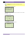
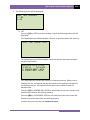
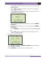
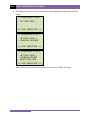
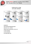
d. The following screen will be displayed:
STATION:
_
↑/↓ TO POSITION
"ENTER" TO ACCEPT
Type the station name using the alpha-numeric keypad and then press the [ENTER]
key.
e. The following screen will be displayed:
CIRCUIT:
_
↑/↓ TO POSITION
"ENTER" TO ACCEPT
Type the circuit information using the alpha-numeric keypad and then press the
[ENTER] key.
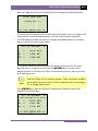
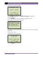
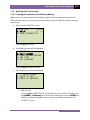
f. The following screen will be displayed:
MANUFACTURER:
_
↑/↓ TO POSITION
"ENTER" TO ACCEPT
Type the manufacturer name using the alpha-numeric keypad and then press the
[ENTER] key.
21
TRM-20 AND TRM-40 USER’S MANUAL
REV 1
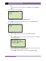
g. The following screen will be displayed:
MODEL:
_
↑/↓ TO POSITION
"ENTER" TO ACCEPT
Type the model information using the alpha-numeric keypad and then press the
[ENTER] key.
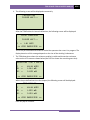
h. The following screen will be displayed:
SERIAL NUMBER:
_
↑/↓ TO POSITION
"ENTER" TO ACCEPT
Type the serial number using the alpha-numeric keypad and then press the [ENTER]
key.
i.
The following screen will be displayed:
KVA RATING:
_
↑/↓ TO POSITION
"ENTER" TO ACCEPT
Type the transformer’s KVA rating using the alpha-numeric keypad and then press the
[ENTER] key.
22
REV 1
j.
TRM-20 AND TRM-40 USER’S MANUAL
The following screen will be displayed:
OPERATOR:
_
↑/↓ TO POSITION
"ENTER" TO ACCEPT
Type the operator’s name using the alpha-numeric keypad and then press the [ENTER]
key.
All header information will be saved, and you will be returned to the “START-UP” menu.
23
TRM-20 AND TRM-40 USER’S MANUAL
3.7
REV 1
Setting the Date and Time
To set the date and time:
a. Start from the “START-UP” menu:
11/01/11
1. RUN TEST
09:06:21
2. SETUP
22°C
72°F
3. USER DIAGNOSTICS
Press the [2] key (SETUP)
b. The following screen will be displayed:
1. RECORD ID
2. PRINT RECORD
3. SAVE/RESTORE RECORD
4. SET TIME
5. SET LANGUAGE
Press the [4] key (SET TIME).
c. The following screen will be displayed:
ENTER DATE
MM-DD-YY
_
Type the current date using the keypad. The following screen will be displayed:
ENTER TIME
HH:MM:SS
_
Enter the time using the keypad. When the time has been entered, you will be
immediately returned to the “START-UP” menu.
24
REV 1
3.8
TRM-20 AND TRM-40 USER’S MANUAL
Setting the Interface Language
Follow the steps below to set the interface language (English, Spanish, or Turkish):
a. Start from the “START-UP” menu:
11/01/11
1. RUN TEST
09:06:21
2. SETUP
22°C
72°F
3. USER DIAGNOSTICS
Press the [2] key (SETUP).
b. The following screen will be displayed:
1. RECORD ID
2. PRINT RECORD
3. SAVE/RESTORE RECORD
4. SET TIME
5. SET LANGUAGE
Press the [5] key (SET LANGUAGE).
c. The following screen will be displayed:
1. ENGLISH
2. TURKISH
3. SPANISH
Select the preferred interface language by pressing the corresponding key on the
keypad ([1], [2], or [3]). The interface language will be set and a confirmation screen
will be displayed as shown below:
ENGLISH SET
Press any key to return to the “START-UP” menu.
25
TRM-20 AND TRM-40 USER’S MANUAL
3.9
REV 1
Performing a Resistance Test
a. Start from the “START-UP” menu:
11/01/11
1. RUN TEST
09:06:21
2. SETUP
22°C
72°F
3. USER DIAGNOSTICS
Press the [1] key (RUN TEST).
b. The following screen will be displayed:
1. RESISTANCE TEST
2. SPECIAL RES TEST
3. DYNAMIC LTC TEST
4. DEGAUSS WINDING
Press the [1] key (RESISTANCE TEST).
c. The following screen will be displayed:
LTC OR VTG REGULATOR?
1. YES
2. NO
Press the [2] key (NO).
d. The following screen will be displayed:
1. V1, V2
2. V1 ONLY
RES TEST
RES TEST
Press the [1] key (V1, V2 RES TEST) if you would like to perform a V1 & V2 test.
Press the [2] key (V1 ONLY RES TEST) if you would like to perform a V1 test only.
26
REV 1
TRM-20 AND TRM-40 USER’S MANUAL
e. The following menu will be displayed:
SELECT TEST CURRENT:
1. 1A
2. 5A
3. 10A
4. 20A
5. 40A
6. CUSTOM
Select the test current by pressing the corresponding numeric key on the keypad. Press
the [6] key (CUSTOM) if you would like to enter a custom test current and then enter
the current (between 1A-40A) on the next screen.
f. The following screen will be displayed:
CONVERT READINGS TO
STANDARD TEMP?
1. YES
2. NO
1. YES
Press the [1] key (YES) if you wish to convert readings to standard temperature.
The following screen will be displayed:
WINDING MATERIAL:
1. COPPER,
TK=234.5
2. ALUMINUM,
TK=225.0
3. MANUALLY ENTER TK
Press the [1] key (COPPER, Tk=234.5) to select copper as the winding material.
Continue to step g.
Press the [2] key (ALUMINUM, Tk=225.0) to select aluminum as the winding
material. Continue to step g.
Press the [3] key (MANUALLY ENTER Tk) to manually enter the Tk value. The
following screen will be displayed:
27
TRM-20 AND TRM-40 USER’S MANUAL
REV 1
TK:
230.0°C
↑↓ to adjust tk
"ENTER" to accept
You can increase the Tk value by 0.5°C increments by pressing the [PAPER ∧
Contrast] key.
You can decrease the Tk value by 0.5°C increments by pressing the [PAPER ∨
Contrast] key.
Press the [ENTER] key to confirm the temperature setting. Continue to step g.
2. NO
Press the [2] key (NO) if you do NOT wish to convert readings to standard
temperature. Continue to step i.
g. The following screen will be displayed:
D.U.T. TEMP:
25.0°C
77.0°F
↑↓ to adjust tk
"ENTER" to accept
Use the [PAPER ∧ Contrast] and [PAPER ∨ Contrast] keys to adjust the D.U.T.
(Device Under Test) temperature.
Press the [ENTER] key to confirm the D.U.T. temperature setting.
h. The following screen will be displayed:
REFERENCE TEMP:
75.0°C
167.0°F
↑↓ to adjust tk
"ENTER" to accept
Use the [PAPER ∧ Contrast] and [PAPER ∨ Contrast] keys to adjust the
reference temperature.
Press the [ENTER] key to confirm the reference temperature setting.
28
REV 1
T
TRM-20
AND
D TRM-40 USER’S
U
MANUAL
The TRM will calculate
c
thee equivalent resistance value
v
at this new
tem
mperature.
NOTE
i.
The followingg warning screen will be displayed:
***** WARNING!
! *****
DANGERO
OUS FLAS
SH-OVER
WILL OC
CCUR IF CABLES
ARE DIS
SCONNECT
TED!
*******
********
*******
This warning is a remindeer that the next
n sequencce of test steeps will run current
c
thro
ough
th
he test load..
Press any keyy to continuee.
j.
The followingg screen will be displayed:
- V1 & V2 TE
EST 10
0 amp test
"start
t" to run test
or
"sto
op" to abort
Press the [ST
TART] key to
t run the teest.
k. The followingg screen will be displayed momentarily:
cal
libratin
ng
ple
ease wait...
29
TRM-20
0 AND TRM-40 USER’S MANUAL
M
R 1
REV
A
After
the TRM
M finishes itss internal calibration, the following screen
s
will be
b displayed:
*XFM
MR CHARGING*
ple
ease wait...
** XFMR
R ENERGIZED! **
This is only an
n informatio
onal screen to
t remind th
he operator that
t
a test iss in progress. The
display duration of this message
m
depends on thee size of the winding’s
w
inductance.
l.
The TRM dete
ermines wheen the resisttance readin
ng is stable and
a displays the resistance
vaalues on the
e LCD screen
n as shown below:
b
TEST IN PROGR
RESS
I
=
10.01 AMPS
R1
=
1.465
R2
=
1.448
14
mΩ
mΩ
The TRM will continue th
he test and update
u
the reesistance values on the LCD screen.
W
While
the tesst is in progress, you can
n press the [E
ENTER] ke
ey to save the current
reeadings from
m the LCD screen to the TRM’s internal working memory. Yo
ou can store up
to
o 99 readinggs per test.
Although
A
thiis process caan be used to
o store multtiple readinggs when testing a
Load
L
Tap Changer (LTC) or Voltage Regulator,
R
a more conveenient metho
od is
also
a available. Please seee section 3.1
10 for inform
mation about performingg an
LTC
L or Voltagge Regulator test.
NOTE
Iff the [ENTE
ER] key is prressed, the data
d
is saved
d and the following screeen will be
displayed on the LCD screeen:
TEST IN PROGR
RESS
14
AVING TEST <===
===> SA
I
=
10.01 AMPS
R1
=
1.465
R2
=
1.448
mΩ
mΩ
R ENERGIZED! **
** XFMR
30
REV 1
TRM-20 AND TRM-40 USER’S MANUAL
Once the data is saved, the following screen will be displayed:
TEST IN PROGRESS
14
===> TEST SAVED! <===
I
=
10.01 AMPS
R1
=
1.465
R2
=
1.448
mΩ
mΩ
** XFMR ENERGIZED! **
Press the [STOP] key to stop running the test. The test results will be displayed as
shown:
TEST RESULTS
I
=
10.01 AMPS
R1
=
1.465
R2
=
1.448
mΩ
mΩ
Press any key to continue.
m. The following screen will be displayed:
PRINT TEST RESULTS?
1. YES
2. NO
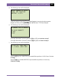
1. YES
Press the [1] key (YES) to print the test results on the built-in thermal printer. A
sample test results printout is shown in Figure 5. Continue to step n.
2. NO
Press the [2] key (NO) to bypass printing of the test results. Continue to step n.
31
TRM-20 AND TRM-40 USER’S MANUAL
REV 1
n. The following screen will be displayed:
KEEP THIS READING?
1. YES
2. NO
1. YES
Press the [1] key (YES) to save the reading. One of the following screens will be
displayed:
The following screen will be displayed if there is no previous data in the memory:
===> TEST SAVED!
<===
The following screen will be displayed if previous data for the same test type is
stored in the memory:
PREVIOUS DATA IN BUF
11/03/11
14:49:09
1. APPEND PREV. DATA
2. CLEAR PREV. DATA
The TRM retains the current test results in its working memory. When a test is
finished, the user can append the new test results to the previous test results in
the working memory, as long as the unit’s power has not been turned off
between tests.
Press the [1] key (APPEND PREV. DATA) to append the current test results to the
previous test results in the working memory.
Press the [2] key (CLEAR PREV. DATA) to only save the current test results and
discard any previous data from the working memory.
In either case, press any key and continue to step o.
32
REV 1
TRM-20 AND TRM-40 USER’S MANUAL
2. NO
If you do not wish to save the reading, press the [2] key (NO) and continue to
step o.
o. The following screen will be displayed:
RUN ANOTHER TEST?
1. YES
2. NO
Press the [1] key (YES) to run another test. Return to step b.
Press the [2] key (NO) if you do not want to run another test. Continue to step p.
p. The following screen will be displayed:
SAVE THIS RECORD?
1. YES
2. NO
1. YES
Press the [1] key (YES) to save the test record. Continue to step q.
2. NO
Press the [2] key (NO) if you do not want to save the test record. The following
screen will be displayed:
ARE YOU SURE?
DATA WILL BE LOST!
1. DO NOT SAVE RECORD
2. SAVE RECORD
Press the [1] key (DO NOT SAVE RECORD) if you do not want to save the record.
You will be returned to the “START-UP” menu.
Press the [2] key (SAVE RECORD) to save the record. Continue to step q.
33
TRM-20
0 AND TRM-40 USER’S MANUAL
M
R 1
REV
q. The followingg screen will be displayed:
record number
n
0
01
has been
n saved!
The
e record num
mber is automatically asssigned and incremented
d by the TRM
M.
NOTE
Press any keyy to return to
o the “STARTT-UP” menu
u.
Figure 5. Typical Res
sistance Testt Results Printout
34
REV 1
3.10
TRM-20 AND TRM-40 USER’S MANUAL
Performing a Load Tap Changer / Voltage Regulator Resistance Test
The Load Tap Changer/Voltage Regulator Resistance Test can be used to conveniently measure
the resistance at each tap position. Once the number of taps has been entered, the TRM will
request the user to set the tap position, starting with the lower taps, then to neutral, and then
to the raise taps. At each tap position, the resistance is measured, displayed on the LCD screen,
and stored. The TRM then instructs the user to change to the next tap position and repeat the
testing process.
Use the steps below to perform an LTC/Voltage Regulator Test:
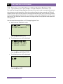
a. Start from the “START-UP” menu:
11/07/11
1. RUN TEST
08:49:15
2. SETUP
22°C
72°F
3. USER DIAGNOSTICS
Press the [1] key (RUN TEST).
b. The following screen will be displayed:
1. RESISTANCE TEST
2. SPECIAL RES TEST
3. DYNAMIC LTC TEST
4. DEGAUSS WINDING
Press the [1] key (RESISTANCE TEST).
c. The following screen will be displayed:
LTC OR VTG REGULATOR?
1. YES
2. NO
Press the [1] key (YES).
35
TRM-20 AND TRM-40 USER’S MANUAL
REV 1
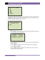
d. The following screen will be displayed
ENTER NUMBER OF RAISE
TAPS, NOT COUNTING
NEUTRAL (1-23):
Type the number of taps the LTC or Voltage Regulator has using the alpha-numeric
keypad, and then press the [ENTER] key. We will enter “3” for our example.
e. The following screen will be displayed:
3 LOWER, -N-, 3 RAISE
IS THIS CORRECT?
1.YES
2.NO
If the tap information is correct, press the [1] key (YES) and continue to step f.
If the tap information is incorrect, press the [2] key (NO) and return to step d.
f. The following screen will be displayed:
1. V1, V2
2. V1 ONLY
RES TEST
REST TEST
Press the [1] key (V1, V2 RES TEST) if you would like to perform a V1 & V2 test. Continue
to step g.
Press the [2] key (V1 ONLY RES TEST) if you would like to perform a V1 test only.
Continue to step g.
36
REV 1
TRM-20 AND TRM-40 USER’S MANUAL
g. The following screen will be displayed:
SELECT TEST CURRENT:
1. 1A
2. 5A
3. 10A
4. 20A
5. 40A
6. CUSTOM
Select the test current by pressing the corresponding numeric key on the keypad. Press
the [6] key (CUSTOM) if you would like to enter a custom test current and then enter
the current (between 1A-40A) on the next screen.
h. The following screen will be displayed:
CONVERT READINGS TO
STANDARD TEMP?
1. YES
2. NO
1. YES
Press the [1] key (YES) if you wish to convert readings to standard temperature.
The following screen will be displayed:
WINDING MATERIAL:
1. COPPER,
TK=234.5
2. ALUMINUM,
TK=225.0
3. MANUALLY ENTER TK
Press the [1] key (COPPER, Tk=234.5) to select copper as the winding material.
Continue to step i.
Press the [2] key (ALUMINUM, Tk=225) to select aluminum as the winding
material. Continue to step i.
Press the [3] key (MANUALLY ENTER Tk) to manually enter the Tk value. The
following screen will be displayed:
37
TRM-20 AND TRM-40 USER’S MANUAL
REV 1
TK:
230.0°C
↑↓ to adjust tk
"ENTER" to accept
You can increase the Tk value by 0.5°C increments by pressing the [PAPER ∧
Contrast] key.
You can decrease the Tk value by 0.5°C increments by pressing the [PAPER ∨
Contrast] key.
Press the [ENTER] key to confirm the temperature setting. Continue to step i.
2. NO
Press the [2] key (NO) if you do NOT wish to convert readings to standard
temperature. Continue to step k.
i.
The following screen will be displayed:
D.U.T. TEMP:
25.0°C
77.0°F
↑↓ to adjust tk
"ENTER" to accept
Use the [PAPER ∧ Contrast] and [PAPER ∨ Contrast] keys to adjust the D.U.T.
(Device Under Test) temperature.
Press the [ENTER] key to confirm the D.U.T. temperature setting.
j.
The following screen will be displayed:
REFERENCE TEMP:
75.0°C
167.0°F
↑↓ to adjust tk
"ENTER" to accept
Use the [PAPER ∧ Contrast] and [PAPER ∨ Contrast] keys to adjust the
reference temperature.
Press the [ENTER] key to confirm the reference temperature setting.
38
REV 1
T
TRM-20
AND
D TRM-40 USER’S
U
MANUAL
The TRM will calculate
c
thee equivalent resistance value
v
at this new
tem
mperature.
NOTE
k. The followingg screen will be displayed:
***** WARNING!
! *****
DANGERO
OUS FLAS
SH-OVER
WILL OC
CCUR IF CABLES
ARE DIS
SCONNECT
TED!
*******
********
*******
Press any keyy to continuee.
l.
The followingg screen will be displayed:
- V1 & V2 TE
EST 40
0 AMP TEST
set tap to 3 lower
"START
T" to RUN TEST
OR
"STO
OP" TO ABORT
Seet the LTC or Voltage Reegulator tap position to the
t position indicated on
o the screen
n. To
ch
hange tap po
ositions, preess and hold the [RAISE
E] or [LOW
WER] LTC con
ntrol button on
th
he front pan
nel. Release the
t button when
w
the tap
p position haas been set to
t the position
in
ndicated on the screen. Press the [S
START] keyy.
m. The followingg screen will be displayed momentarily:
cal
libratin
ng
ple
ease wait...
39
TRM-20 AND TRM-40 USER’S MANUAL
REV 1
After the TRM finishes its internal calibration, the following screen will be displayed:
*XFMR CHARGING*
please wait...
I
=
1.01 AMPS
** XFMR ENERGIZED! **
n. The TRM determines when the resistance reading is stable and displays the resistance
values on the LCD screen as shown below:
TEST IN PROGRESS
I
=
40.04 AMPS
R1
=
1.461
R2
=
1.469
14
mΩ
mΩ
** XFMR ENERGIZED! **
Press the [ENTER] key to accept and save the readings.
o. The following screen will be displayed:
TEST IN PROGRESS
14
===> SAVING TEST <===
I
=
40.04 AMPS
R1
=
1.461
R2
=
1.469
mΩ
mΩ
** XFMR ENERGIZED! **
Once the reading has been saved, the following screen will be displayed momentarily:
TEST IN PROGRESS
14
===> TEST SAVED! <===
I
=
40.04 AMPS
R1
=
1.461
R2
=
1.469
mΩ
mΩ
40
REV 1
TRM-20 AND TRM-40 USER’S MANUAL
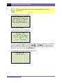
p. After saving the readings, the following screen will be displayed:
set tap to 2 lower
("START" to CONTINUE)
** XFMR ENERGIZED! **
Set the LTC or Voltage Regulator tap position to the position indicated on the LCD screen
and press the [START] key.
The TRM will continue the test and display the results as in step n. Repeat steps l
through o for all “Lower” positions and then through all “Raise” positions.
q. The following screen will be displayed after the last “Raise” position’s resistance reading
is stored:
PRINT RECORD?
1. YES
2. NO
1. YES
Press the [1] key (YES) to print the test results on the built-in thermal printer. A
Typical LTC/Voltage Regulator test report is shown in Figure 6. Continue to step
r.
2. NO
Press the [2] key (NO) to bypass printing of the test results. Continue to step r.
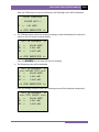
r. The following screen will be displayed:
SAVE THIS RECORD?
1. YES
2. NO
1. YES
Press the [1] key (YES) to save the test record. The following screen will be
displayed:
41
TRM-20 AND TRM-40 USER’S MANUAL
REV 1
record number 02
has been saved!
Press any key to return to the “START-UP” menu.
2. NO
If you do not wish to save the test record, press the [2] key (NO). The following
screen will be displayed:
ARE YOU SURE?
DATA WILL BE LOST!
1. DO NOT SAVE RECORD
2. SAVE RECORD
Press the [1] key (DO NOT SAVE RECORD) to NOT save the test record. You will
be returned to the “START-UP” menu.
42
REV 1
TRM-20 AND TRM-40 USER’S MANUAL
Figure 6. Typical LTC/Voltage Regulator Test Report Printout
43
TRM-20 AND TRM-40 USER’S MANUAL
3.11
REV 1
Performing a Special Resistance Test
The Special Resistance Test is used to conduct a resistance test for a pre-defined period ranging
from 1 to 45 minutes. The resistance data is recorded at one minute intervals. Use the steps
below to perform a Special Resistance Test:
a. Start from the “START-UP” ” menu:
11/07/11
1. RUN TEST
08:49:15
2. SETUP
22°C
72°F
3. USER DIAGNOSTICS
Press the [1] key (TEST XFMR).
b. The following screen will be displayed:
1. RESISTANCE TEST
2. SPECIAL RES TEST
3. DYNAMIC LTC TEST
4. DEGAUSS WINDING
Press the [2] key (SPECIAL RES TEST).
c. The following screen will be displayed:
1. V1, V2
2. V1 ONLY
SPEC TEST
SPEC TEST
Press the [1] key (V1, V2 SPEC TEST) to perform a V1 & V2 special resistance test.
Continue to step d.
Press the [2] key (V1 ONLY SPEC TEST) to perform a V1 special resistance test.
44
REV 1
TRM-20 AND TRM-40 USER’S MANUAL
d. The following screen will be displayed:
enter special test
time minutes (1-45)
_
Enter the test time (between 1 to 45 minutes) using the alpha-numeric keypad, and
then press the [ENTER] key.
e. The following screen will be displayed:
SELECT TEST CURRENT:
1. 1A
2. 5A
3. 10A
4. 20A
5. 40A
6. CUSTOM
Select the test current by pressing the corresponding numeric key on the keypad. Press
the [6] key (CUSTOM) if you would like to enter a custom test current and then enter
the current (between 1A-40A) on the next screen.
f. The following screen will be displayed:
CONVERT READINGS TO
STANDARD TEMP?
1. YES
2. NO
1. YES
Press the [1] key (YES) if you wish to convert readings to standard temperature.
The following screen will be displayed:
WINDING MATERIAL:
1. COPPER,
TK=234.5
2. ALUMINUM,
TK=225.0
3. MANUALLY ENTER TK
45
TRM-20 AND TRM-40 USER’S MANUAL
REV 1
Press the [1] key (COPPER, Tk=234.5) to select copper as the winding material.
Continue to step g.
Press the [2] key (ALUMINUM, Tk=225) to select aluminum as the winding
material. Continue to step g.
Press the [3] key (MANUALLY ENTER Tk) to manually enter the Tk value. The
following screen will be displayed:
TK:
230.0°C
↑↓ to adjust tk
"ENTER" to accept
You can increase the Tk value by 0.5°C increments by pressing the [PAPER ∧
Contrast] key.
You can decrease the Tk value by 0.5°C increments by pressing the [PAPER ∨
Contrast] key.
Press the [ENTER] key to confirm the temperature setting. Continue to step e.
2. NO
Press the [2] key (NO) if you do NOT wish to convert readings to standard
temperature. Continue to step i.
g. The following screen will be displayed:
D.U.T. TEMP:
25.0°C
77.0°F
↑↓ to adjust tk
"ENTER" to accept
Use the [PAPER ∧ Contrast] and [PAPER ∨ Contrast] keys to adjust the D.U.T.
(Device Under Test) temperature.
Press the [ENTER] key to confirm the D.U.T. temperature setting.
46
REV 1
TRM-20 AND TRM-40 USER’S MANUAL
h. The following screen will be displayed:
REFERENCE TEMP:
75.0°C
167.0°F
↑↓ to adjust tk
"ENTER" to accept
Use the [PAPER ∧ Contrast] and [PAPER ∨ Contrast] keys to adjust the
reference temperature.
Press the [ENTER] key to confirm the reference temperature setting.
i.
The following warning screen will be displayed:
***** WARNING! *****
DANGEROUS FLASH-OVER
WILL OCCUR IF CABLES
ARE DISCONNECTED!
********************
This warning is a reminder that the next sequence of test steps will run current through
the test load.
Press any key to continue.
j.
The following screen will be displayed:
- V1 & V2 TEST 40 AMP TEST
"START" to RUN TEST
OR
"STOP" TO ABORT
Press the [START] key to run the test.
47
TRM-20 AND TRM-40 USER’S MANUAL
REV 1
k. The following screen will be displayed momentarily:
calibrating
please wait...
After the TRM finishes its internal calibration, the following screen will be displayed:
*XFMR CHARGING*
please wait...
I
=
1.01 AMPS
** XFMR ENERGIZED! **
This is only an informational screen to remind the operator that a test is in progress. The
display duration of this message depends on the size of the winding’s inductance.
l.
The TRM determines when the resistance reading is stable and shows the resistance
value on the LCD screen as shown below (the first line shows the remaining test time):
REMAINING TIME = 00:59
I
=
40.04 AMPS
R1
=
1.844
R2
=
2.025
mΩ
mΩ
** XFMR ENERGIZED! **
When the pre-defined test time has elapsed, the following screen will be displayed:
TEST RESULTS
I
=
40.04 AMPS
R1
=
1.839
R2
=
2.051
mΩ
mΩ
** XFMR ENERGIZED! **
Press any key to continue.
48
REV 1
T
TRM-20
AND
D TRM-40 USER’S
U
MANUAL
m. The followingg screen will be displayed:
SAVE THIS RECOR
RD?
1. YES
2. NO
1. YES
Press the [1] key (YES) to save the test reecord. Contin
nue to step m.
2. NO
Press the [2] key (NO) if you do
d not wantt to save thee test record. The following
screen
n will be disp
played:
ARE
E YOU SURE?
DAT
TA WILL BE LOST!
3. DO
D
NOT SAVE
S
RECORD
4. SAVE
S
REC
CORD
Press the [1] key (DO NOT SA
AVE RECORD
D) if you do not
n want to save
s
the record.
You will
w be return
ned to the “SSTART-UP” menu.
m
Press the [2] key (SAVE RECO
ORD) to save the record. Continue to
o step m.
n. The followingg screen will be displayed:
record number
n
0
03
has been
n saved!
• The
T record number is automatically assigned and
d incrementted by the TR
RM.
• Once
O
the testt record hass been saved
d, it can be reecalled and printed (3.15.3
and 3.15.4 fo
or further infformation). Figure 7 sho
ows a typical Special Testt
NOTES
re
eport printo
out.
Press any keyy to return to
o the “STARTT-UP” menu
u.
49
TRM-20 AND TRM-40 USER’S MANUAL
REV 1
Figure 7. Typical Special Test Report Printout
50
REV 1
3.12
T
TRM-20
AND
D TRM-40 USER’S
U
MANUAL
P
Performing
a Dynamic LTC Test
The Dynaamic LTC Tesst is used to conduct a reesistance test while the LTC or Voltaage Regulato
or is
switchingg taps. The test
t will run for 240 seco
onds to allow
w the LTC or Voltage Reggulator enou
ugh
time to switch through all of the taps duringg the test. Th
he resistancee data is reco
orded
continuo
ously during the test period. Use thee following stteps to perfo
orm a Dynam
mic LTC Testt.
NOTE
Dynamic LTC Test ressults can onlly be saved to
t an external USB Flash
h drive. If you
would likke to save yo
our test results, please be
b sure to co
onnect a USB
B Flash drive to
the unit before
b
perfo
orming this test.
t
a. Sttart from the “START-UP
P” menu:
11/07/1
11
1. RUN TEST
T
08:49:15
2. SETUP
P
22°C
72°°F
3. USER DIAGNOST
TICS
Press the [1] key (RUN TEST).
T
b. The followingg screen will be displayed:
1. RESIS
STANCE TE
EST
2. SPECIAL RES TEST
T
3. DYNAM
MIC LTC TEST
T
4. DEGAU
USS WINDI
ING
Press the [3] key (DYNAM
MIC LTC TESTT).
c. The followingg screen will be displayed:
***** WARNING!
! *****
DANGERO
OUS FLAS
SH-OVER
WILL OC
CCUR IF CABLES
ARE DIS
SCONNECT
TED!
*******
********
*******
This warning reminds thee operator th
hat the next sequence of
o test steps will run currrent
th
hrough the test
t load. Preess any key to
t continue..
51
TRM-20 AND TRM-40 USER’S MANUAL
REV 1
d. The following screen will be displayed:
SET LTC/VREG To
LOWEST TAP POSITION.
PRESS
ANY KEY WHEN READY
Set the LTC or Voltage Regulator to the lowest position either manually or by pressing
and holding the LTC [LOWER] button. Press any key to continue.
e. The following warning screen will be displayed:
DYNAMIC LTC TEST
"START" TO RUN TEST
OR
"STOP" TO ABORT
Press the [START] key to run the test.
f. The following screen will be displayed momentarily:
calibrating
please wait...
After the TRM has finished its internal calibration, the following screen will be displayed:
*XFMR CHARGING*
please wait...
I
=
1.01 AMPS
** XFMR ENERGIZED! **
When the TRM has determined that the resistance reading is stable, the following
screen will be displayed:
52
REV 1
TRM-20 AND TRM-40 USER’S MANUAL
READY TO CAPTURE DATA
PRESS "ENTER"
- OR LTC RAISE/LOWER
TO START TIMING...
Press the [ENTER] key or the LTC [RAISE] or [LOWER] key to continue.
g. The TRM will start capturing data and the following screen will be displayed:
RUNNING DYNAMIC
LTC TEST T=239
"STOP" TO END TEST
** XFMR ENERGIZED! **
The second line on the screen will display the remaining time for the test. While the
TRM captures data, you can press the LTC [RAISE] or [LOWER] button to cycle
through the LTC or Voltage Regulator’s taps. You can wait for the remainder of the test
time or you can press the [STOP] key at any time to end the test. If you have
completed cycling through the taps, it is recommended to stop the test manually. If the
test is performed for the duration of 240 seconds, the graph printout will be rather long!
h. When the test time has expired or the test is stopped manually, the following screen will
be displayed.
PRINTING REPORT
PLEASE WAIT...
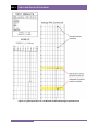
The test results will be printed on the unit’s built-in thermal printer. A sample test
results printout is shown in Figure 8. The following screen will be displayed when
printing is finished:
SAVE THIS RECORD TO
THUMB DRIVE?
1.YES
2.NO
53
TRM-20 AND TRM-40 USER’S MANUAL
REV 1
1. YES
Press the [1] key (YES) to save the test results to the connected USB Flash drive.
The following screen will be displayed:
REC_001 SAVED TO
THUMB DRIVE.
Press any key to return to the “START-UP” menu.
2. NO
Press the [2] key (NO) if you do not want to save the test results. The following
screen will be displayed:
ARE YOU SURE?
DATA WILL BE LOST!
1.DO NOT SAVE RECORD
2.SAVE RECORD
Press the [1] key (DO NOT SAVE RECORD). You will be returned to the “STARTUP” menu.
54
REV 1
TRM-20 AND TRM-40 USER’S MANUAL
Figure 8. Typical Dynamic LTC Test Results Printout Showing an Opened Circuit
55
TRM-20 AND TRM-40 USER’S MANUAL
3.13
REV 1
Performing a Diagnostic Test
In diagnostic mode, the TRM can run a resistance test, display the sense voltages, and test
current on the TRM. This feature can be used to verify the TRM’s voltage and current readings
against an external meter. Use the steps below to perform a diagnostic test:
a. Start from the “START-UP” menu:
11/07/11
1. RUN TEST
08:49:15
2. SETUP
22°C
72°F
3. USER DIAGNOSTICS
Press the [3] key (USER DIAGNOSTICS).
b. The following screen will be displayed:
SELECT TEST CURRENT:
1. 1A
2. 5A
3. 10A
4. 20A
5. 40A
6. CUSTOM
Select the test current by pressing the corresponding numeric key on the keypad. Press
the [6] key (CUSTOM) if you would like to enter a custom test current and then enter
the current (between 1A-40A) on the next screen.
c. The following warning screen will be displayed:
***** WARNING! *****
DANGEROUS FLASH-OVER
WILL OCCUR IF CABLES
ARE DISCONNECTED!
********************
Press any key to continue.
56
REV 1
TRM-20 AND TRM-40 USER’S MANUAL
d. The following screen will be displayed:
- USER DIAG TEST "START" TO RUN TEST
OR
"STOP" TO ABORT
Press the [START] key.
e. The V1, V2, and test current (I) will be displayed as shown below:
USER DIAGNOSTICS
V1 = 35.86 mV
V2 = 38.43 mV
I = 20.020 A
** XFMR ENERGIZED! **
Press the [STOP] key to end the test and return to the “START-UP” menu.
57
TRM-20 AND TRM-40 USER’S MANUAL
3.14
REV 1
Demagnetizing the Transformer Core
You can demagnetize the transformer core using the steps below:
a. Start from the “Start-Up” menu:
11/07/11
1. RUN TEST
08:49:15
2. SETUP
22°C
72°F
3. USER DIAGNOSTICS
Press the [1] key (RUN TEST
b. The following screen will be displayed:
1. RESISTANCE TEST
2. SPECIAL RES TEST
3. DYNAMIC LTC TEST
4. DEGAUSS WINDING
Press the [4] key (DEGAUSS WINDING).
c. The following screen will be displayed:
DEGAUSS CURRENT:
1. 0.5 AMP
2. 1 AMP
3. 2 AMPS
4. 5 AMPS
5. 10 AMPS
Select the degaussing current by pressing the corresponding key on the alpha-numeric
keypad.
d. The following screen will be displayed:
THIS MAY TAKE SEVERAL
MINUTES TO COMPLETE
"ENTER" to continue
Press the [ENTER] key to continue.
58
REV 1
TRM-20 AND TRM-40 USER’S MANUAL
e. The degaussing process will start and updates will be displayed on the screen as shown
below:
* DEGAUSSING XFMR *
-> SETTING CORE...
** XFMR ENERGIZED! **
* DEGAUSSING XFMR *
SETTING CORE...
-> CHARGING REVERSE
** XFMR ENERGIZED! **
* DEGAUSSING XFMR *
SETTING CORE...
CHARGING REVERS
-> RESETTING CORE
** XFMR ENERGIZED! **
When the process is complete, you will be returned to the “START-UP” menu.
59
TRM-20 AND TRM-40 USER’S MANUAL
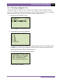
3.15
REV 1
Working with Test Records
3.15.1. Viewing the Contents of the Working Memory
Whenever a test is performed and the reading is kept, the data is temporarily stored in the
TRM’s working memory. You can view the test reading in the unit’s working memory using the
steps below:
a. Start from the “START-UP” menu:
11/07/11
1. RUN TEST
08:49:15
2. SETUP
22°C
72°F
3. USER DIAGNOSTICS
Press the [2] key (SETUP).
b. The following screen will be displayed:
1. RECORD ID
2. PRINT RECORD
3. SAVE/RESTORE RECORD
4. SET TIME
5. SET LANGUAGE
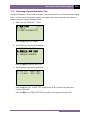
Press the [2] key (PRINT RECORD).
c. The following screen will be displayed:
PRINT RECORD
1. PRINT TO LCD
2. PRINT TO PRINTER
1. PRINT TO LCD
Press the [1] key (PRINT TO LCD) to view the test record on the LCD screen. Use
the [PAPER ∨ Contrast] key to scroll to the next page. Press the [STOP] key
when you are done viewing the test record, and you will be returned to the
“START-UP” menu.
60
REV 1
TRM-20 AND TRM-40 USER’S MANUAL
2. PRINT TO PRINTER
Press the [2] key (PRINT TO PRINTER) to print the test record on the unit’s
thermal printer. You will then be returned to the “START-UP” menu.
61
TRM-20
0 AND TRM-40 USER’S MANUAL
M
R 1
REV
3.15.2. Saving
S
Tes
st Results to a Test Record
R
After perrforming a te
est, the userr is presenteed the option
n to save thee test resultss to the unit’’s
Flash EEP
PROM or to a USB Flash Drive. If thee test resultss are not saved immediately after
performing a test, th
hey will still remain
r
in the working memory
m
and can be saved later, as lo
ong
as a new test has nott been perfo
ormed and th
he unit has not
n been turrned off. Follow the step
ps
below to
o save the test results fro
om the workking memoryy to a test reecord (the fo
ollowing
procedurre can also be
b used to ree-save a resttored test reecord to a neew memory location or to
t a
USB Flash
h Drive):
a. Perform a tesst or restore a test recorrd to the working memo
ory, and then
n start from the
“SSTART-UP” menu:
m
11/07/1
11
1. RUN TEST
T
08:49:15
2. SETUP
P
22°C
72°°F
3. USER DIAGNOST
TICS
Press the [2] key (SETUP).
b. The followingg screen will be displayed:
1. RECOR
RD ID
2. PRINT
T RECORD
3. SAVE/
/RESTORE RECORD
4. SET TIME
T
5. SET LANGUAGE
L
Press the [3] key (SAVE/R
RESTORE REECORD).
c. The followingg screen will be displayed:
1. RESTO
ORE RECOR
RD
2. SAVE RECORD
3. RECOR
RD DIRECT
TORY
4. ERASE
E RECORD
5. COPY TO THUMB
B DRIVE
Option 5 (COPYY TO THUMB
B DRIVE) willl be listed on
nly if a USB Flash
F
drive iss
con
nnected to the Auto-Ohm
m.
NOTE
Press the [2] key (SAVE RECORD).
R
62
REV 1
TRM-20 AND TRM-40 USER’S MANUAL
If a USB Flash drive is connected to the unit, continue to step d.
If a USB Flash drive is NOT connected to the unit, continue to step e.
d. The following screen will be displayed:
1. SAVE INTERNALLY
2. SAVE TO THUMB DRIVE
1. SAVE INTERNALLY
Press the [1] key (SAVE INTERNALLY) to save the test record to the unit’s Flash
EEPROM. Continue to step e.
2. SAVE TO THUMB DRIVE
Press the [2] key (SAVE TO THUMB DRIVE) to save the test record to the
connected USB Flash Drive. The following screen will be displayed:
REC_001 SAVED TO
THUMB DRIVE
Press any key to return to the “START-UP” menu.
e. The following screen will be displayed:
RECORD NUMBER 2
HAS BEEN SAVED!
Press any key to return to the “START-UP” menu.
63
TRM-20
0 AND TRM-40 USER’S MANUAL
M
R 1
REV
3.15.3. Restoring
R
a Test Rec
cord From Flash EEP
PROM
Use the steps
s
below to restore a test record from the TR
RM’s internaal Flash EEPR
ROM to the
working memory:
a. Sttart from the “START-UP
P” menu:
11/09/1
11
1. RUN TEST
T
12:13:15
2. SETUP
P
22°C
72°°F
3. USER DIAGNOST
TICS
Press the [2] key (SETUP).
b. The followingg screen will be displayed:
1. RECOR
RD ID
2. PRINT
T RECORD
3. SAVE/
/RESTORE RECORD
4. SET TIME
T
5. SET LANGUAGE
L
Press the [3] key (SAVE/R
RESTORE REECORD).
c. The followingg screen will be displayed:
1. RESTO
ORE RECOR
RD
2. SAVE RECORD
3. RECOR
RD DIRECT
TORY
4. ERASE
E RECORD
5. COPY TO THUMB
B DRIVE
Option 5 (COPYY TO THUMB
B DRIVE) willl be listed on
nly if a USB Flash
F
drive iss
con
nnected to the unit.
NOTE
Press the [1] key (RESTORE RECORD))
64
REV 1
T
TRM-20
AND
D TRM-40 USER’S
U
MANUAL
d. The followingg screen will be displayed:
REST
TORE RECO
ORD
1. ENTER
R RECORD NUMBER
2. SCROL
LL TO SEL
LECT
If you
y have a USB
U Flash drivve inserted in the unit’s “USB MEM”” port, the
folllowing screeen will be dissplayed insteead of the above screen
n:
NOTE
1.
1 INTERN
NAL STORA
AGE
2.
2 THUMB DRIVE
Pre
ess the [1] key (INTERNA
AL STORAGEE).
The
e following screen
s
will be
b displayed::
RESTO
ORE RECOR
RD
1.
1 ENTER RECORD N
NUMBER
2.
2 SCROLL
L TO SELE
ECT
Con
ntinue with the steps beelow.
1. ENTER
R RECORD NUMBER
N
Press the [1] key (ENTER REC
CORD NUMBER) if you kn
now the reco
ord number that
you would
w
like to restore. Thee following screen
s
will be
b displayed::
RESTORE
E RECORD
NUMBER:
Type the
t record number
n
usingg the alpha-numeric keyypad and theen press thee
[ENT
TER] key. Th
he following screen will be displayed
d:
65
TRM-20 AND TRM-40 USER’S MANUAL
REV 1
RECORD RESTORED!
PRINT RECORD?
1.YES
2.NO
Press the [1] key (YES) if you would like to print the restored test record on the
unit’s built-in thermal printer. You will be returned to the “START-UP” menu
after printing is finished.
Press the [2] key (NO) if you do not want to print the restored test record. You
will be returned to the “START-UP” menu.
2. SCROLL TO SELECT
Press the [2] key (SCROLL TO SELECT) to scroll through a directory of the test
records. The following screen will be displayed:
RECORDS DIRECTORY
"UP" TO SCROLL FWD
"DWN" TO SCROLL RVS
Press the [PAPER ∧ Contrast] key or the [PAPER ∨ Contrast] key to
display the next or previous test record, respectively. The basic test record
information will be displayed as shown below:
#1
08/26/11
16:47
NUM OF TESTS: 2
V1, V2 TEST
When you have located the test record that you would like to restore, press the
[ENTER] key. The following screen will be displayed:
66
REV 1
TRM-20 AND TRM-40 USER’S MANUAL
RECORD RESTORED!
PRINT RECORD?
1.YES
2.NO
Press the [1] key (YES) if you would like to print the restored test record on the
unit’s built-in thermal printer. You will be returned to the “START-UP” menu
after printing is finished.
Press the [2] key (NO) if you do not want to print the restored test record. You
will be returned to the “START-UP” menu.
67
TRM-20 AND TRM-40 USER’S MANUAL
REV 1
3.15.4. Restoring a Test Record From a USB Flash Drive
Use the steps below to restore a test record from a USB Flash drive to the TRM’s working
memory:
a. Make sure the USB Flash drive containing the test record(s) is inserted in the TRM’s USB
Flash drive port (“USB MEM” port). Then start from the “START-UP” menu:
11/10/11
1. RUN TEST
12:13:15
2. SETUP
22°C
72°F
3. USER DIAGNOSTICS
Press the [2] key (SETUP).
b. The following screen will be displayed:
1. RECORD ID
2. PRINT RECORD
3. SAVE/RESTORE RECORD
4. SET TIME
5. SET LANGUAGE
Press the [3] key (SAVE/RESTORE RECORD).
c. The following screen will be displayed:
1. RESTORE RECORD
2. SAVE RECORD
3. RECORD DIRECTORY
4. ERASE RECORD
5. COPY TO THUMB DRIVE
Press the [1] key (RESTORE RECORD)
68
REV 1
TRM-20 AND TRM-40 USER’S MANUAL
d. The following screen will be displayed:
1. INTERNAL STORAGE
2. THUMB DRIVE
Press the [2] key (THUMB DRIVE).
e. The following screen will be displayed:
RESTORE THUMB DRIVE
REC_
Type the record number that you would like to restore using the alpha-numeric keypad
and then press the [ENTER] key.
f. The test record will be restored to the unit’s working memory, and the following screen
will be displayed:
REC_001 RESTORED!
PRINT RECORD?
1.YES
2.NO
Press the [1] key (YES) if you would like to print the restored test record on the unit’s
built-in thermal printer. You will be returned to the “START-UP” menu after printing is
finished.
Press the [2] key (NO) if you do not want to print the restored test record. You will be
returned to the “START-UP” menu.
69
TRM-20 AND TRM-40 USER’S MANUAL
REV 1
3.15.5. Copying Test Records to a USB Flash Drive
Use the steps below to copy one or all test records from the unit’s Flash EEPROM to a
connected USB Flash drive:
a. Make sure a USB Flash drive is connected to the unit’s “USB MEM” port, and then start
from the “START-UP” menu:
11/11/11
1. RUN TEST
13:13:15
2. SETUP
22°C
72°F
3. USER DIAGNOSTICS
Press the [2] key (SETUP).
b. The following screen will be displayed:
1. RECORD ID
2. PRINT RECORD
3. SAVE/RESTORE RECORD
4. SET TIME
5. SET LANGUAGE
Press the [3] key (SAVE/RESTORE RECORD).
c. The following screen will be displayed:
1. RESTORE RECORD
2. SAVE RECORD
3. RECORD DIRECTORY
4. ERASE RECORD
5. COPY TO THUMB DRIVE
Press the [5] key (COPY TO THUMB DRIVE).
70
REV 1
TRM-20 AND TRM-40 USER’S MANUAL
d. The following screen will be displayed:
COPY REC TO THUMB DRV
1.COPY SINGLE RECORD
2.COPY ALL RECORDS
1. COPY SINGLE RECORD
Press the [1] key (COPY SINGLE RECORD) to copy a single test record from the
unit’s Flash EEPROM to the connected USB Flash drive. The following screen will
be displayed:
ENTER RECORD NUMBER
TO COPY TO FLASH DRV
NUMBER:
Type the record number using the alpha-numeric keypad and then press the
[ENTER] key. The test record will be copied to the USB Flash drive and the
following screen will be displayed:
REC_011 SAVED To
THUMB DRIVE
Press any key to return to the “START-UP” menu.
71
TRM-20 AND TRM-40 USER’S MANUAL
REV 1
2. COPY ALL RECORDS
Press the [2] key (COPY ALL RECORDS) to copy all test records from the TRM’s
Flash EEPROM to the connected USB Flash drive. All test records will be copied
from the unit to the connected USB Flash drive. The following screen will be
displayed when the process is finished:
ALL RECORDS HAVE BEEN
TRANSFERRED TO THUMB
DRIVE!
Press any key to return to the “START-UP” menu.
72
REV 1
TRM-20 AND TRM-40 USER’S MANUAL
3.15.6. Printing a Test Record Directory
Use the steps below to print a directory of the test records stored in the TRM’s Flash EEPROM:
a. Start from the “START-UP” menu:
11/10/11
1. RUN TEST
12:13:15
2. SETUP
22°C
72°F
3. USER DIAGNOSTICS
Press the [2] key (SETUP).
b. The following screen will be displayed:
1. RECORD ID
2. PRINT RECORD
3. SAVE/RESTORE RECORD
4. SET TIME
5. SET LANGUAGE
Press the [3] key (SAVE/RESTORE RECORD).
c. The following screen will be displayed:
1. RESTORE RECORD
2. SAVE RECORD
3. RECORD DIRECTORY
4. ERASE RECORD
5. COPY TO THUMB DRIVE
Press the [3] key (RECORD DIRECTORY).
73
TRM-20 AND TRM-40 USER’S MANUAL
REV 1
d. The following screen will be displayed:
PRINT DIRECTORY
1. FULL DIRECTORY
2. SHORT DIRECTORY
Press the [1] key (FULL DIRECTORY) to print the entire directory of test records. After
the directory is printed, you will be returned to the “START-UP” menu.
Press the [2] key (SHORT DIRECTORY) to print a short directory. This lists the last 10
records stored in the TRM’s memory. After the directory is printed, you will be returned
to the “START-UP” menu.
A typical test record directory printout is shown in Figure 9.
Figure 9. Typical Test Record Directory Printout
74
REV 1
TRM-20 AND TRM-40 USER’S MANUAL
3.15.7. Erasing Test Records from the Flash EEPROM
Follow the steps below to erase test records from the unit’s Flash EEPROM:
a. Start from the “START-UP” menu:
11/10/11
1. RUN TEST
12:13:15
2. SETUP
22°C
72°F
3. USER DIAGNOSTICS
Press the [2] key (SETUP).
b. The following screen will be displayed:
1. RECORD ID
2. PRINT RECORD
3. SAVE/RESTORE RECORD
4. SET TIME
5. SET LANGUAGE
Press the [3] key (RESTORE RECORD).
c. The following screen will be displayed:
1. RESTORE RECORD
2. SAVE RECORD
3. RECORD DIRECTORY
4. ERASE RECORD
5. COPY TO THUMB DRIVE
Press the [4] key (ERASE RECORD).
75
TRM-20
0 AND TRM-40 USER’S MANUAL
M
R 1
REV
d. The followingg screen will be displayed:
ERASE RECO
ORD
1. ERASE
E SINGLE
E REC.
2. ERASE
E ALL RE
ECORDS
"STOP" TO EXIT
E
If you
y have a USB
U Flash drive inserted in the unit’ss “USB MEM
M” port, the
folllowing screeen will be displayed insttead of the above
a
screen
n:
NOTE
1.
1
ERASE INTERNA
AL REC
2.
2
ERASE
E THUMB DRV
D
REC
Pre
ess the [1] key
k (ERASE INTERNAL REEC). The follo
owing screen will be
dissplayed:
ERA
ASE RECOR
RD
1.
1
ERASE SINGLE REC.
2.
2
ERASE
E ALL REC
CORDS
"STO
OP" TO EX
XIT
Co
ontinue with the steps below.
1. ERASEE SINGLE REC
C.
Press the [1] key (ERASE SING
GLE REC.) to erase a singgle record. The followingg
screen
n will be disp
played:
ERASE
E RECORD
NUMBE
ER:
Type the
t record number
n
that you would like
l to erasee, and then press
p
the
[ENT
TER] key. Th
he following screen will be displayed
d:
76
REV 1
TRM-20 AND TRM-40 USER’S MANUAL
RECORD NUMBER 21
ERASED!
Press any key to return to the “START-UP” menu.
2. ERASE ALL RECORDS
Press the [2] key (ERASE ALL RECORDS) to erase all records stored in the TRM’s
Flash EEPROM. The following screen will be displayed:
ERASE ALL RECORDS!
ARE YOU SURE?
"ENTER" TO CONTINUE
You can press the [STOP] key to cancel the process and return to the “STARTUP” menu.
Press the [ENTER] key to proceed with deleting all the test records from the
unit’s Flash EEPROM. The following screen will be displayed during the erasure
process:
ERASING RECORDS
PLEASE WAIT...
The following screen will be displayed when all test records have been
completely erased:
RECORDS ERASED!
Press any key to return to the “START-UP” menu.
77
TRM-20 AND TRM-40 USER’S MANUAL
3.16
REV 1
Erasing Test Records from a USB Flash Drive
Follow the steps below to erase test records from a USB Flash drive:
a. Make sure a USB Flash drive is connected to the unit’s “USB MEM” port, and then start
from the “START-UP” menu:
11/10/11
1. RUN TEST
12:13:15
2. SETUP
22°C
72°F
3. USER DIAGNOSTICS
Press the [2] key (SETUP).
b. The following screen will be displayed:
1. RECORD ID
2. PRINT RECORD
3. SAVE/RESTORE RECORD
4. SET TIME
5. SET LANGUAGE
Press the [3] key (RESTORE RECORD).
c. The following screen will be displayed:
1. RESTORE RECORD
2. SAVE RECORD
3. RECORD DIRECTORY
4. ERASE RECORD
5. COPY TO THUMB DRIVE
Press the [4] key (ERASE RECORD).
d. The following screen will be displayed:
1. ERASE INTERNAL REC
2. ERASE THUMB DRV REC
Press the [2] key (ERASE THUMB DRV REC).
78
REV 1
TRM-20 AND TRM-40 USER’S MANUAL
e. The following screen will be displayed:
ERASE RECORD
1. ERASE SINGLE REC.
2. ERASE ALL RECORDS
"STOP" TO EXIT
1. ERASE SINGLE REC.
Press the [1] key (ERASE SINGLE REC.) to erase a single test record from the
connected USB Flash drive. The following screen will be displayed:
ERASE THUMB DRIV
REC_
Type the record number that you would like to erase using the alpha-numeric
keypad and then press the [ENTER] key. The test record will be erased from
the USB Flash drive and the following screen will be displayed:
THUMB DRIVE REC001
ERASED!
Press any key to continue. You will be returned to the beginning of step e. Press
the [STOP] key to return to the “START-UP” menu.
2. ERASE ALL RECORDS
Press the [2] key (ERASE ALL RECORDS) to delete all test records from the
connected USB Flash drive. The following warning screen will be displayed:
ERASE ALL THUMB DRIVE
RECORDS!
ARE YOU SURE?
"ENTER" TO CONTINUE
79
TRM-20 AND TRM-40 USER’S MANUAL
REV 1
Press the [STOP] key if you do not want to erase all the test records. You will be
returned to the “START-UP” menu.
Press the [ENTER] key to proceed with deleting all the test records from the
connected USB Flash drive. The following screen will be displayed when all the
records have been erased:
ALL THUMB DRIVE
RECORDS ERASED!
Press any key to return to the “START-UP” menu.
80
REV 1
3.17
TRM-20 AND TRM-40 USER’S MANUAL
Converting Resistance Measurements
The TRM can convert the resistance reading of the device under test at its present temperature
to the equivalent resistance value at a different temperature. The conversion is accomplished
by the following formula:
Rs = Rm (Ts + Tk) / (Tm + Tk)
Where:
Rs is the resistance at desired temperature
Rm is the measured resistance
Ts is the desired reference temperature
Tm is the temperature at which the resistance was measured
Tk is the constant used for the winding material
Tk = 234.5 for copper
Tk = 240.0 for aluminum
81
1520 S. Hellman Ave • Ontario, CA 91761 • USA
Phone: 909-923-9390 • Fax: 909-923-9391
www.vanguard-instruments.com
Copyright © 2015 by Vanguard Instruments Company, Inc.
TRM-20/40 User’s Manual • Revision 1.3 • August 24, 2015 • TA