1
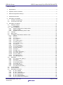
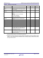
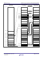
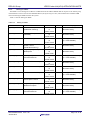
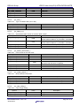
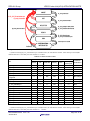
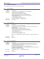
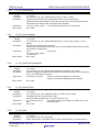
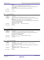
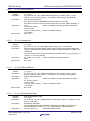
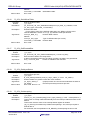
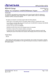
APPLICATION NOTE RZ/A1H Group JPEG Codec Unit(JCU) Sample Driver R01AN1862EJ0100 Rev.1.00 Jun.20.2014 Introduction This application note describes the sample driver which is decoded from the JPEG image data, and encoded to the JPEG image data. The JPEG Codec Unit(JCU) sample driver offers the following features: The JPEG image data is converted to a raw image data of the RGB565, ARGB8888, and YCbCr422 formats. The raw image data of the YCbCr format is converted to a JPEG image data. The interrupt information is used for notice of conversion completion. Target Device RZ/A1H When applying the sample program covered in this application note to another microcomputer, modify the program according to the specifications for the target microcomputer and conduct an extensive evaluation of the modified program. R01AN1862EJ0100 Jun.20.2014 Rev.1.00 Page 1 of 40 RZ/A1H Group JPEG Codec Unit(JCU) APPLICATION NOTE Table of contents 1. Specifications .......................................................................................................................................... 4 2. Operation Check Conditions ................................................................................................................... 5 3. Reference Application Note(s) ................................................................................................................ 6 4. Peripheral Functions ............................................................................................................................... 7 5. Description of Hardware ......................................................................................................................... 8 5.1 Hardware Configuration ................................................................................................................... 8 5.2 List of Pins to be Used ..................................................................................................................... 9 6. Description of Software ......................................................................................................................... 10 6.1 Operation Outline .......................................................................................................................... 10 6.1.1 Preparations ........................................................................................................................... 11 6.2 Memory Mapping ........................................................................................................................... 12 6.2.1 Section Assignment in Sample Code ..................................................................................... 13 6.2.2 Setting for MMU ..................................................................................................................... 16 6.2.3 Exception Processing Vector Table ....................................................................................... 17 6.3 Interrupt ......................................................................................................................................... 17 6.4 Basic Types ................................................................................................................................... 18 6.5 Constants, Enumerations and Error code ..................................................................................... 19 6.5.1 Version ................................................................................................................................... 19 6.5.2 errnum_t ................................................................................................................................. 19 6.5.3 jcu_errorcode_t ...................................................................................................................... 20 6.5.4 jcu_codec_t ............................................................................................................................ 20 6.5.5 jcu_continue_type_t ............................................................................................................... 20 6.5.6 jcu_detail_error_t .................................................................................................................... 20 6.5.7 jcu_int_detail_error_t .............................................................................................................. 21 6.5.8 jcu_swap_t.............................................................................................................................. 21 6.5.9 jcu_sub_sampling_t ................................................................................................................ 21 6.5.10 jcu_decode_format_t .............................................................................................................. 21 6.5.11 jcu_jpeg_format_t ................................................................................................................... 21 6.5.12 jcu_huff_t ................................................................................................................................ 22 6.5.13 jcu_table_no_t ........................................................................................................................ 22 6.5.14 jcu_status_information_t ........................................................................................................ 22 6.5.15 jcu_codec_status_t ................................................................................................................. 22 6.5.16 jcu_cbcr_offset_t .................................................................................................................... 22 6.5.17 jcu_interrupt_line_t ................................................................................................................. 23 6.5.18 jcu_interrupt_lines_t ............................................................................................................... 23 6.6 Structures ...................................................................................................................................... 24 6.6.1 jcu_count_mode_param_t ...................................................................................................... 24 6.6.2 jcu_buffer_t ............................................................................................................................. 24 6.6.3 jcu_buffer_param_t ................................................................................................................ 25 6.6.4 jcu_decode_param_t .............................................................................................................. 25 6.6.5 jcu_image_info_t .................................................................................................................... 25 6.6.6 jcu_encode_param_t .............................................................................................................. 25 6.6.7 jcu_internal_information_t ...................................................................................................... 26 6.7 List of Variables ............................................................................................................................. 27 6.8 List of Functions ............................................................................................................................ 28 6.9 Description of function ................................................................................................................... 31 6.9.1 R_JCU_Initialize ..................................................................................................................... 31 6.9.2 R_JCU_Terminate .................................................................................................................. 31 6.9.3 R_JCU_TerminateAsync ........................................................................................................ 31 6.9.4 R_JCU_SelectCodec ............................................................................................................. 32 6.9.5 R_JCU_SetCountMode .......................................................................................................... 32 6.9.6 R_JCU_SetPauseForImageInfo ............................................................................................. 32 R01AN1862EJ0100 Jun.20.2014 Rev.1.00 Page 2 of 40 RZ/A1H Group 6.9.7 6.9.8 6.9.9 6.9.10 6.9.11 6.9.12 6.9.13 6.9.14 6.9.15 6.9.16 6.9.17 6.9.18 6.9.19 6.9.20 6.9.21 6.9.22 6.9.23 6.9.24 6.9.25 6.9.26 JPEG Codec Unit(JCU) APPLICATION NOTE R_JCU_SetErrorFilter ............................................................................................................ 32 R_JCU_Start .......................................................................................................................... 32 R_JCU_StartAsync ................................................................................................................ 33 R_JCU_Continue ................................................................................................................... 33 R_JCU_ContinuetAsync ......................................................................................................... 33 R_JCU_SetDecodeParam ..................................................................................................... 34 R_JCU_GetImageInfo ............................................................................................................ 34 R_JCU_SetEncodeParam...................................................................................................... 34 R_JCU_SetQuantizationTable ............................................................................................... 34 R_JCU_SetHuffmanTable ...................................................................................................... 35 R_JCU_GetEncodedSize ....................................................................................................... 35 R_JCU_GetAsyncStatus ........................................................................................................ 35 R_JCU_OnInterrupting ........................................................................................................... 35 R_JCU_OnInterrupted ............................................................................................................ 36 R_JCU_OnInitialize ................................................................................................................ 36 R_JCU_OnFinalize ................................................................................................................. 36 R_JCU_SetDefaultAsync ....................................................................................................... 36 R_JCU_SetInterruptCallbackCaller ........................................................................................ 37 R_JCU_OnEnableInterrupt .................................................................................................... 37 R_JCU_OnDiableInterrupt ..................................................................................................... 37 7. Sample Codes ...................................................................................................................................... 39 8. Documents for Reference ..................................................................................................................... 39 R01AN1862EJ0100 Jun.20.2014 Rev.1.00 Page 3 of 40 RZ/A1H Group 1. JPEG Codec Unit(JCU) APPLICATION NOTE Specifications Table 1.1 lists the Peripheral Functions and Their Applications, and Figure 1.1 shows the Operation Overview. Table 1.1 Peripheral Functions to be Used and their Uses Peripheral functions JPEG Codec Unit(JCU) Interrupt controller(INTC) Serial Communication Interface with FIFO(SCIF) Ch2 Uses Converts image data. The processor will receive interrupts when decoding or encoding is completed, failed, or paused. Output sample code message. Terminal software (outputs sample code message) Host PC MESSAGE R7S72100 R7S72100 CPU board RTK772100BC00000BR Figure 1.1 Serial interface (RS-232C cable) Operation Overview R01AN1862EJ0100 Jun.20.2014 Rev.1.00 Page 4 of 40 RZ/A1H Group 2. JPEG Codec Unit(JCU) APPLICATION NOTE Operation Check Conditions The sample code accompanying this application note has been run and confirmed under the conditions below. Table 2.1 Operation Check Conditions Item Contents MCU used Operating frequency* Operating voltage Integrated development environment C compiler Operating mode Communication setting of terminal software Board used Device used R01AN1862EJ0100 Jun.20.2014 Rev.1.00 RZ/A1H CPU clock (Iφ): 400MHz Image processing clock (Gφ): 266.67MHz Internal bus clock (Bφ): 133.33MHz Peripheral clock 1 (P1φ): 66.67MHz Peripheral clock 0 (P0φ): 33.33MHz Power supply voltage (I/O): 3.3V Power supply voltage (Internal): 1.18V ® ARM integrated development environment TM ARM Development Studio 5 (DS-5 ) Version 5.16 ARM C/C++ Compiler/Linker/Assembler Ver.5.03 [Build 102] Compiler options (excluding additional directory path) -O3 -Ospace --cpu=Cortex-A9 --littleend --arm --apcs=/interwork --no_unaligned_access --fpu=vfpv3_fp16 -g Boot mode 0 (CS0-space 16-bit booting) • Communication speed: 115200bps • Data length: 8 bits • Parity: None • Stop bit length: 1 bit • Flow control: None GENMAI Board • RTK772100BC00000BR (R7S72100 CPU board) • RTK77210000B00000BR (R7S72100 Option board) LCD. (Only the sample should be used. ) • Serial interface (D-sub 9-pin connector) Page 5 of 40 RZ/A1H Group 3. JPEG Codec Unit(JCU) APPLICATION NOTE Reference Application Note(s) For additional information associated with this document, refer to the following application note(s). RZ/A1H Example of Initialization (R01AN1646EJ) RZ/A1H Definition of I/O Register file “iodefine.h” (R01AN1860JJ) RZ/A1H Group OS porting layer “OSPL” Sample Program (R01AN1887EJ) R01AN1862EJ0100 Jun.20.2014 Rev.1.00 Page 6 of 40 RZ/A1H Group 4. JPEG Codec Unit(JCU) APPLICATION NOTE Peripheral Functions The basic functions of the JCU are described in the RZ/A1H Group User’s Manual: Hardware. R01AN1862EJ0100 Jun.20.2014 Rev.1.00 Page 7 of 40 RZ/A1H Group 5. 5.1 JPEG Codec Unit(JCU) APPLICATION NOTE Description of Hardware Hardware Configuration Figure 5-1 shows examples of hardware devices connected. GENMAI board Power supply ULINK2(ICE) Option board (Optional) To host PC’s USB LCD output (Optional) To host PC’s serial port Figure 5-1 Examples of Hardware Devices Connected R01AN1862EJ0100 Jun.20.2014 Rev.1.00 Page 8 of 40 RZ/A1H Group 5.2 JPEG Codec Unit(JCU) APPLICATION NOTE List of Pins to be Used Table 5-1 lists the pins to be used and their functions. Table 5-1 Pins to be Used and their Functions Pin name I/O Description None R01AN1862EJ0100 Jun.20.2014 Rev.1.00 Page 9 of 40 RZ/A1H Group JPEG Codec Unit(JCU) APPLICATION NOTE 6. Description of Software 6.1 Operation Outline Figure 6-1 shows the sequence of image data converted using the synchronous function. CPU RAM JCU Initialize the JCU. (R_JCU_Initialize function) Creates an input image in RAM. Sets conversion information in the JCU. (R_JCU_SelectCodec function, R_JCU_SetDecodeParam function) Starts JCU to initiate conversion. (R_JCU_Start function) Output image data Performs termination processing for the JCU. (R_JCU_Terminate function) Figure 6-1 Sequence of image data conversion(using the synchronous function). Please refer to OS transplantation layer OSPL for RZ/A1H group PFV,JCU (R01AN1887EJ) , when using the asynchronous function. This sample program has processing of 3 kinds, "decoding processing of a JPEG picture"(R_JCU_SampleDecode function), "decoding and encoding processing of a JPEG picture"(R_JCU_SampleDecodeEncode function) and "the processing indicated after decoding of a JPEG picture"(R_JCU_SampleDecodeAndShow function). R01AN1862EJ0100 Jun.20.2014 Rev.1.00 Page 10 of 40 RZ/A1H Group 6.1.1 JPEG Codec Unit(JCU) APPLICATION NOTE Preparations The following preparations in Sample Code. 1. Terminal software is started in a host PC and it's established as follows. (In the case of Tera Term) Figure 6.2 2. Setting of a serial port When a sample program is executed, a message is output at a terminal as follows. Figure 6.3 Message output at sample program execution R01AN1862EJ0100 Jun.20.2014 Rev.1.00 Page 11 of 40 RZ/A1H Group 6.2 JPEG Codec Unit(JCU) APPLICATION NOTE Memory Mapping Figure 6.4 shows the Address Space of the RZ/A1H group and the Memory Mapping of the GENMAI Board RTK772100BC00000BR. In this sample code, the code and data used in the ROM area is located in the NOR flash memory connected to the CS0 space, and the code and data used in the RAM area is located in the large-capacity on-chip RAM. RZ/A1H group Address space RTK772100BC0000BR Memory map Others (2550MB) Others (2550MB) Large-capacity on-chip RAM (10MB) Large-capacity on-chip RAM mirror space SPI multi I/O bus space 2 (64MB) SPI multi I/O bus mirror space 2 SPI multi I/O bus space 1 (64MB) SPI multi I/O bus mirror space 1 CS5 space (64MB) CS4 space (64MB) CS5 mirror space CS4 mirror space CS3 space (64MB) CS3 mirror space CS2 space (64MB) CS2 mirror space CS1 space (64MB) CS1 mirror space CS0 space (64MB) CS0 mirror space Others (502MB) Others (502MB) Large-capacity on-chip RAM (10MB) Large-capacity on-chip RAM (10MB) SPI multi I/O bus space 2 (64MB) Serial flash memory (64MB) SPI multi I/O bus space 1 (64MB) Serial flash memory (64MB) CS5 space (64MB) CS4 space (64MB) User area CS3 space (64MB) SDRAM (64MB) CS2 space (64MB) SDRAM (64MB) CS1 space (64MB) NOR flash memory (64MB) CS0 space (64MB) NOR flash memory (64MB) H'FFFF FFFF H'60A0 0000 H'6000 0000 H'5C00 0000 H'5800 0000 Mirror space H'5000 0000 H'4C00 0000 H'4800 0000 H'4400 0000 H'4000 0000 H'20A0 0000 H'2000 0000 H'1C00 0000 H'1800 0000 Normal space H'1000 0000 H'0C00 0000 H'0800 0000 H'0400 0000 H'0000 0000 Figure 6.5 Memory Mapping R01AN1862EJ0100 Jun.20.2014 Rev.1.00 Page 12 of 40 RZ/A1H Group 6.2.1 JPEG Codec Unit(JCU) APPLICATION NOTE Section Assignment in Sample Code In this sample code, the exception processing vector table and the IRQ interrupt handler are assigned to the large-capacity on-chip RAM, and they are executed in such RAM to speed up the interrupt processing. The transfer processing from the NOR flash memory area which is the program code of the exception processing vector table and the IRQ interrupt handler to the large-capacity on-chip RAM area, the clear to zero processing for the data selection without initial data, and the initialization for the data selection with initial data are executed by using the scatter-loading function. Refer to "Image structure and generation" in "ARM Compiler toolchain Using the Linker" provided by the ARM for more information about the scatter-loading function. Table 6.1 and Table 6.2 list the Sections to be Used in this sample code. Figure 6.6 shows the Section Assignment for the initial condition of the sample code and the condition after using the scatter-loading function. Table 6.1 Sections to be Used (1/2) Area Name Description VECTOR_TABLE RESET_HANDLER Exception processing vector table Program code area of reset handler processing This area consists of the following sections. • INITCA9CACHE (L1 cache setting) • INIT_TTB (MMU setting) • RESET_HANDLER (Reset handler) CODE_BASIC_SETUP Program code area to optimize operating frequency and flash memory InRoot This area consists of the sections located in the root area such as C standard library. CODE_FPU_INIT CODE_RESET CODE_IO_REGRW CODE CONST R01AN1862EJ0100 Jun.20.2014 Program code area for NEON and VFP initializations This area consists of the following sections. • CODE_FPU_INIT • FPU_INIT Program code area for hardware initialization This area consists of the following sections. • CODE_RESET (Startup processing) • INIT_VBAR (Vector base setting) Program code area for read/write functions of I/O register Program code area for defaults All the Code type sections which do not define section names with C source are assigned in this area. Constant data area for defaults All the RO Data type sections which do not define section names with C source are assigned in this area. Rev.1.00 Type Code Code Loading Area FLASH FLASH Execution Area FLASH FLASH Code FLASH FLASH Code and RO Data Code FLASH FLASH FLASH FLASH Code FLASH FLASH Code FLASH FLASH Code FLASH FLASH RO Data FLASH FLASH Page 13 of 40 RZ/A1H Group Table 6.2 JPEG Codec Unit(JCU) APPLICATION NOTE Sections to be Used (2/2) Area Name Description VECTOR_MIRROR_ TABLE Type Loading Area FLASH Execution Area LRAM Exception processing vector table Code (Section to transfer data to large-capacity on-chip RAM) CODE_HANDLER_ Program code area for user-defined Code FLASH LRAM functions of IRQ interrupt handler JMPTBL CODE_HANDLER Program code area of IRQ interrupt Code FLASH LRAM handler This area consists of the following sections. • CODE_HANDLER • IRQ_FIQ_HANDLER DATA_HANDLER_ Registration table data area for RW Data FLASH LRAM user-defined functions of IRQ interrupt JMPTBL handler ARM_LIB_STACK Application stack area ZI Data LRAM IRQ_STACK IRQ mode stack area ZI Data LRAM FIQ_STACK FIQ mode stack area ZI Data LRAM SVC_STACK Supervisor (SVC) mode stack area ZI Data LRAM ABT_STACK Abort (ABT) mode stack area ZI Data LRAM TTB MMU translation table area ZI Data LRAM ARM_LIB_HEAP Application heap area ZI Data LRAM DATA Data area with initial value for defaults RW Data FLASH LRAM All the RW Data type sections which do not define section names with C source are assigned in this area. BSS Data area without initial value for defaults ZI Data LRAM All the ZI Data type sections which do not define section names with C source area assigned in this area. Notes: 1. "FLASH" and "LRAM" shown in Loading Area and Execution Area indicate the NOR flash memory area and the large-capacity on-chip RAM area respectively. 2. Basically the section name is set to be the same as the region's, however it consists of some sections in the areas of RESET_HANDLER, InRoot, CODE_FPU_INIT, CODE_RESET, CODE, CONST, CODE_HANDLER, DATA, and BSS. Refer to the ARM compiler toolchain manual about the region and the section. R01AN1862EJ0100 Jun.20.2014 Rev.1.00 Page 14 of 40 RZ/A1H Group JPEG Codec Unit(JCU) APPLICATION NOTE Section assignment (Load view) RZ/A1H group Address space Memory allocation after executing scatter-loading H'209F FFFF H'FFFF FFFF Section assignment (Execution view) Clear to zero BSS Initialize data with initial value DATA H'200B 8000 ARM_LIB_HEAP H'2003 8000 Secure area such as stack area H'2003 4000 H'2003 2000 H'2003 0000 H'2002 E000 H'2002 C000 TTB ABT_STACK SVC_STACK FIQ_STAC IRQ_STACK ARM_LIB_STACK H'2002 4000 Initialize data with initial value DATA_HANDLER_JMPTBL CODE_HANDLER H'2002 0100 CODE_HANDLER_JMPTBL H'2002 0000 VECTOR_MIRROR_TABLE H'2000 0000 H'03FF FFFF H'4000 0000 DATA DATA_HANDLER_JMPTBL H'20A0 0000 H'2000 0000 CODE_HANDLER Large-capacity on-chip RAM (10MB) CODE_HANDLER_JMPTBL CONST H'1C00 0000 CODE H'1000 0000 H'0C00 0000 H'0800 0000 CODE_RESET CODE_FPU_INIT CODE_FPU_INIT InRoot InRoot CODE_BASIC_SETUP CODE_BASIC_SETUP RESER_HANDLER Figure 6.6 CS0 space (64MB) CODE CODE_RESET H'0000 0200 H'0400 0000 CONST CODE_IO_REGRW CODE_IO_REGRW H'1800 0000 H'0000 0000 Transfer program code which requires speeding up to onchip RAM H'0000 0100 VECTOR_MIRROR_TABLE H'0000 0000 VECTOR_TABLE Transfer exception processing vector to on-chip RAM RESER_HANDLER VECTOR_TABLE Section Assignment R01AN1862EJ0100 Jun.20.2014 Rev.1.00 Page 15 of 40 RZ/A1H Group 6.2.2 JPEG Codec Unit(JCU) APPLICATION NOTE Setting for MMU The MMU is set to manage the 4 GB area in 1MB unit from the address H'0000 0000 in response to the memory map of the hardware resource used for the GENMAI Board. (Set by the ttb_init.s file.) The minimum unit should be 1MB when customizing the MMU based on the system. Table 6.3 lists the Setting for MMU. Table 6.3 Setting for MMU Definition Name M_SIZE_NOR Contents CS0 and CS1 spaces (NOR flash memory) M_SIZE_SDRAM CS2 and CS3 spaces (SDRAM) M_SIZE_CS45 CS4 and CS5 spaces M_SIZE_SPI SPI multi IO bus space 1 and 2 (serial flash memory) Large-capacity on-chip RAM space M_SIZE_RAM M_SIZE_IO_1 On-chip peripheral module and reserved area M_SIZE_NOR_M CS0 and CS1 mirror spaces M_SIZE_SDRAM_M CS2 and CS3 mirror spaces M_SIZE_CS45_M CS4 and CS5 mirror spaces M_SIZE_SPI_M SPI multi IO bus mirror space 1 and 2 M_SIZE_RAM_M Large-capacity on-chip RAM mirror space M_SIZE_IO_2 On-chip peripheral module and reserved area R01AN1862EJ0100 Jun.20.2014 Rev.1.00 Address H'0000 0000 to H'07FF FFFF H'0800 0000 to H'0FFF FFFF H'1000 0000 to H'17FF FFFF H'1800 0000 to H'1FFF FFFF H'2000 0000 to H'209F FFFF H'20A0 0000 to H'3FFF FFFF H'4000 0000 to H'47FF FFFF H'4800 0000 to H'4FFF FFFF H'5000 0000 to H'57FF FFFF H'5800 0000 to H'5FFF FFFF H'6000 0000 to H'609F FFFF H'60A0 0000 to H'FFFF FFFF Size 128MB Memory Type L1 cache enable, Normal memory 128MB L1 cache enable, Normal memory 128MB Strongly-ordered memory (L1 cache disable) 128MB L1 cache enable, Normal memory 10MB L1 cache enable, Normal memory 502MB Strongly-ordered memory (L1 cache disable) 128MB L1 cache disable, Normal memory 128MB L1 cache disable, Normal memory 128MB Strongly-ordered memory (L1 cache disable) 128MB L1 cache disable, Normal memory 10MB L1 cache disable, Normal memory 2550MB Strongly-ordered memory (L1 cache disable) Page 16 of 40 RZ/A1H Group 6.2.3 JPEG Codec Unit(JCU) APPLICATION NOTE Exception Processing Vector Table The RZ/A1H has seven types of exception processing (reset, undefined instruction, software interrupt, prefetch abort, data abort, IRQ, and FIQ). In the case of boot mode 0, the exception processing vector table is assigned to the area from H'0000 0000 to the area of 32 bytes (from H'0000 0000 to H'0000 001F) after the reset cancellation. Figure 6.7 shows the contents of the sample code exception processing vector table as a description example. vector_table LDR pc, =reset_handler LDR pc, =undefined_handler LDR pc, =svc_handler LDR pc, =prefetch_handler LDR pc, =abort_handler LDR pc, =reserved_handler LDR pc, =irq_handler LDR pc, =fiq_handler Figure 6.7 6.3 ; ; ; ; ; ; ; ; 0x0000_0000 0x0000_0004 0x0000_0008 0x0000_000c 0x0000_0010 0x0000_0014 0x0000_0018 0x0000_001c : : : : : : : : Reset exception Undefined instructions exception Software interrupts exceptions Prefetch abort exception Data abort exception Reserved IRQ exception FIQ exception Description Example of Exception Processing Vector Table Interrupt Table 6.4 shows Interrupts using by sample code. Table 6.4 Interrupts using by sample code Interrupt (Source ID) JEDI JDTI R01AN1862EJ0100 Jun.20.2014 Priority JCU_INT_PRI(=2) JCU_INT_PRI(=2) Rev.1.00 Summary Compression/Decompression process. Data transfer process Page 17 of 40 RZ/A1H Group 6.4 JPEG Codec Unit(JCU) APPLICATION NOTE Basic Types Table 6.5 lists the Basic types using in the example code. Table 6.5 Basic types using in the example code Symbol char_t bool_t int_t int8_t int16_t int32_t uint8_t uint16_t uint32_t int_fast32_t uint_fast8_t uint_fast16_t uint_fast32_t uintptr_t size_t bit_flags_fast32_t bit_flags32_t R01AN1862EJ0100 Jun.20.2014 Description 8-bit character Logical data type. The value is true (1) or false (0). The signed integer for this library is a 32-bit signed integer. 8-bit signed integer 16-bit signed integer 32-bit signed integer 8-bit unsigned integer 16-bit unsigned integer 32-bit unsigned integer Fastest 32-bit minimum-width signed integer Fastest 8-bit minimum-width unsigned integer Fastest 16-bit minimum-width unsigned integer Fastest 32-bit minimum-width unsigned integer Same as pointer bit width unsigned integer as physical address Same as pointer bit width unsigned integer as byte size Same as uint_fast32_t bit flags (bit field) Same as uint32_t bit flags (bit field) Rev.1.00 Page 18 of 40 RZ/A1H Group 6.5 JPEG Codec Unit(JCU) APPLICATION NOTE Constants, Enumerations and Error code Table 6.6 Constants Used in Sample Code Section 6.5.1 6.5.2 6.5.3 6.5.4 6.5.5 6.5.6 6.5.7 6.5.8 6.5.9 6.5.10 6.5.11 6.5.12 6.5.13 6.5.14 6.5.15 6.5.16 errnum_t jcu_errorcode_t jcu_codec_t jcu_continue_type_t jcu_detail_error_t jcu_int_detail_error_t jcu_swap_t jcu_sub_sampling_t jcu_decode_format_t jcu_jpeg_format_t jcu_huff_t jcu_table_no_t jcu_status_information_t jcu_codec_status_t jcu_cbcr_offset_t 6.5.17 jcu_interrupt_line_t Version information. Error information. Error code. 0 = No error. Mode selection (Compression or De-compression). Paused factor(continue mode). Error classification of the JCU driver. Particular error code. Swap setting. Sub sample of the decoded image data. Output pixel format of RAW image data. Pixel format of JPEG image data. Type of Huffman table (AC or DC). Quantization table number or Huffman table number. Internal state of the JCU driver. Mode selection information. Cb/Cr range setting. If the pixel format isn’t YCbCr, the JCU_CBCR_OFFSET_0 must be used. The kind of interrupt as the bit flag value. 6.5.18 jcu_interrupt_lines_t Logical sum of the bit flag value jcu_interrupt_line_t. 6.5.1 Table 6.7 Symbol Version Version information Symbol JCU_VERSION JCU_VERSION_STRING 6.5.2 Table 6.8 Description Value - Description JCU version number. Character string of the JCU version number. Value 0 1 Description No error. Other error. The fixed-length arrays size is smaller than data size. Out of memory error occurred when ensure a heap memory. Error when enqueue to FIFO is failed. Error of undefined symbol. There are no next. Error of Read/Write denied. Not implemented. See “errno”. Limitation. The error which can't be executed in this state The error by which a file and a folder aren't found. errnum_t Error information Symbol E_OTHERS E_FEW_ARRAY 2 E_FEW_MEMORY 3 E_FIFO_OVER E_NOT_FOUND_SYMBOL E_NO_NEXT E_ACCESS_DENIED E_NOT_IMPLEMENT_YET E_ERRNO E_LIMITATION E_STATE E_PATH_NOT_FOUND R01AN1862EJ0100 Jun.20.2014 Rev.1.00 4 5 6 7 9 0x0E(=14) 0x0F(=15) 0x10(=16) 0x12(=18) Page 19 of 40 RZ/A1H Group JPEG Codec Unit(JCU) APPLICATION NOTE Symbol E_BAD_COMMAND_ID E_TIME_OUT E_NO_DEBUG_TLS E_EXIT_TEST 6.5.3 Table 6.9 Table 6.10 Table 6.11 Error code Table 6.12 Value 0x0000 0x4501 0x4502 0x4503 0x4504 Description No error has occurred. A parameter provided to a function is incorrect. A function was called in an incorrect state. A function was called in an incorrect mode. Restrictions on JCU driver. jcu_codec_t Mode selection (Compression or De-compression). Value 0 1 Description Compression process. De-compression process. jcu_continue_type_t Paused factor(continue mode). Symbol JCU_INPUT_BUFFER JCU_OUTPUT_BUFFER JCU_GET_IMAGE_INFO 6.5.6 Description The command id number is the outside of the range. Time out There is no debug/work area. See ‘R_OSPL_SET_DEBUG_WORK’ Stop request of the test. jcu_errorcode_t Symbol JCU_ENCODE JCU_DECODE 6.5.5 0x1D(=29) 0x1E(=30) Symbol JCU_ERROR_OK JCU_ERROR_PARAM JCU_ERROR_STATUS JCU_ERROR_CODEC_TYPE JCU_ERROR_LIMITATION 6.5.4 Value 0x16(=22) 0x17(=23) Value 0 1 2 Description Resumes reading input image data. Resumes writing output image data. Clears the process-stopped state caused by requests to read the image information. jcu_detail_error_t Error classification of the JCU driver. Symbol JCU_JCDERR_OK JCU_JCDERR_SOI_NOT_FOUND Value 0x0000 JCU_JCDERR_INVALID_SOF JCU_JCDERR_UNPROVIDED_SOF JCU_JCDERR_SOF_ACCURACY JCU_JCDERR_DQT_ACCURACY JCU_JCDERR_COMPONENT_1 0x4522 0x4523 0x4524 0x4525 JCU_JCDERR_COMPONENT_2 JCU_JCDERR_NO_SOF0_DQT_DHT JCU_JCDERR_SOS_NOT_FOUND JCU_JCDERR_EOI_NOT_FOUND R01AN1862EJ0100 Jun.20.2014 Rev.1.00 0x4521 0x4526 0x4527 0x4528 0x4529 0x452A Description Normal. SOI not detected: SOI not detected until EOI detected. SOF1 to SOFF detected. Unprovided pixel format detected. SOF accuracy error: Other than 8 detected. DQT accuracy error: Other than 0 detected. Component error 1: The number of SOF0 header components detected is other than 1, 3, or 4. Component error 2: The number of components differs between SOF0 header and SOS. SOF0, DQT, and DHT not detected when SOS detected. SOS not detected: SOS not detected until EOI detected. EOI not detected (default). Page 20 of 40 RZ/A1H Group JPEG Codec Unit(JCU) APPLICATION NOTE Symbol JCU_JCDERR_RESTART_INTERVAL JCU_JCDERR_IMAGE_SIZE JCU_JCDERR_LAST_MCU_DATA JCU_JCDERR_BLOCK_DATA 6.5.7 Table 6.13 Value Description The number of data in the restart interval of the Huffman-coding segment is not correct in de-compression. The total number of data in the Huffman-coding segment is not correct in de-compression. The final number of MCU data in the Huffman-coding segment is not correct in de-compression. Particular error code. 0x80 JCU_INT_ERROR_SEGMENT_TOT AL_DATA JCU_INT_ERROR_MCU_BLOCK_D ATA Table 6.14 Description Restart interval data number error detected. Image size error detected. Last MCU data number error detected. Block data number error detected. jcu_int_detail_error_t Symbol JCU_INT_ERROR_RESTART_INTE RVAL_DATA 6.5.8 Value 0x452B 0x452C 0x452D 0x452E 0x40 0x20 jcu_swap_t Swap setting. Symbol JCU_SWAP_NONE JCU_SWAP_BYTE JCU_SWAP_WORD JCU_SWAP_WORD_AND_BYTE JCU_SWAP_LONG_WORD JCU_SWAP_LONG_WORD_AND_BYTE JCU_SWAP_LONG_WORD_AND_WORD JCU_SWAP_LONG_WORD_AND_WORD _AND_BYTE 6.5.9 Table 6.15 Table 6.16 Table 6.17 No swap. Byte swap. Word swap. Word-byte swap. Longword swap. Longword-byte swap. Longword-word swap. Longword-word-byte swap. Sub sample of the decoded image data. Value 0x00 0x01 0x02 0x03 Description No subsampling. Subsamples output data into 1/2. Subsamples output data into 1/4. Subsamples output data into 1/8. jcu_decode_format_t Output pixel format of RAW image data. Symbol JCU_OUTPUT_YCbCr422 JCU_OUTPUT_ARGB8888 JCU_OUTPUT_RGB565 6.5.11 0x07 Description jcu_sub_sampling_t Symbol JCU_SUB_SAMPLING_1_1 JCU_SUB_SAMPLING_1_2 JCU_SUB_SAMPLING_1_4 JCU_SUB_SAMPLING_1_8 6.5.10 Value 0x00 0x01 0x02 0x03 0x04 0x05 0x06 Value 0x00 0x01 0x02 Description YCbCr422 ARGB8888 RGB565 jcu_jpeg_format_t Pixel format of JPEG image data. R01AN1862EJ0100 Jun.20.2014 Rev.1.00 Page 21 of 40 RZ/A1H Group JPEG Codec Unit(JCU) APPLICATION NOTE Symbol JCU_JPEG_YCbCr444 JCU_JPEG_YCbCr422 JCU_JPEG_YCbCr420 JCU_JPEG_YCbCr411 6.5.12 Table 6.18 Table 6.19 Type of Huffman table (AC or DC). Value 0x00 0x01 AC DC Quantization table number or Huffman table number. Value 0x00 JCU_TABLE_NO_1 0x01 JCU_TABLE_NO_2 JCU_TABLE_NO_3 Table 6.20 Description jcu_table_no_t Symbol JCU_TABLE_NO_0 6.5.14 Description YCbCr444 YCbCr422 YCbCr420 YCbCr411 jcu_huff_t Symbol JCU_HUFFMAN_AC JCU_HUFFMAN_DC 6.5.13 Value 0x00 0x01 0x02 0x06 0x02 0x03 Description Quantization table No. 0 (JCQTBL0), or DC/AC Huffman table No. 0 (JCHTBD0 / JCHTBA0) Quantization table No. 1 (JCQTBL1), or DC/AC Huffman table No. 1 (JCHTBD1 / JCHTBA1) Quantization table No. 2 (JCQTBL2) Quantization table No. 3 (JCQTBL3) jcu_status_information_t Internal state of the JCU driver. Symbol JCU_STATUS_UNDEF JCU_STATUS_INIT JCU_STATUS_SELECTED JCU_STATUS_READY Value 0x00 0x01 0x02 JCU_STATUS_RUN JCU_STATUS_INTERRUPTING JCU_STATUS_INTERRUPTED 0x10 0x40 0x80 Description The JCU is uninitialized status. The JCU is initialized status. The JCU mode is selected. The JCU decode/encode is ready, or the JCU decode/encode has been completed. The JCU decode/encode being executed. The state that interrupt occurred. The state after interrupt function executed. Value -1 0 1 Description The state of the JCU mode is not selected. The state of the JCU mode is JCU_ENCODE. The state of the JCU mode is JCU_DECODE. 6.5.15 Table 6.21 jcu_codec_status_t Mode selection information. Symbol JCU_CODEC_NOT_SELECTED JCU_STATUS_ENCODE JCU_STATUS_DECODE 6.5.16 Table 6.22 0x08 jcu_cbcr_offset_t Cb/Cr range setting. Symbol Value Description JCU_CBCR_OFFSET_0 0 Range from -128 to 127 JCU_CBCR_OFFSET_128 1 Range from 0 to 255 If the pixel format isn’t YCbCr, the JCU_CBCR_OFFSET_0 must be used. R01AN1862EJ0100 Jun.20.2014 Rev.1.00 Page 22 of 40 RZ/A1H Group 6.5.17 Table 6.23 JPEG Codec Unit(JCU) APPLICATION NOTE jcu_interrupt_line_t The kind of interrupt as the bit flag value. Symbol JCU_INTERRUPT_LINE_JEDI JCU_INTERRUPT_LINE_JDTI 6.5.18 Table 6.24 Value 0x00000001u 0x00000002u Description Interrupt of JEDI. Interrupt of JDTI. jcu_interrupt_lines_t Logical sum of the bit flag value jcu_interrupt_line_t. Symbol JCU_INTERRUPT_LINE_ALL R01AN1862EJ0100 Jun.20.2014 Rev.1.00 Value 0x00000003u Description Interrupt of both of JEDI and JDTI. Page 23 of 40 RZ/A1H Group 6.6 JPEG Codec Unit(JCU) APPLICATION NOTE Structures Table 6.25 Structures Section 6.6.1 6.6.2 6.6.3 Symbol jcu_count_mode_param_t jcu_buffer_t jcu_buffer_param_t 6.6.4 6.6.5 jcu_decode_param_t jcu_image_info_t 6.6.6 6.6.7 - jcu_encode_param_t jcu_internal_information_t jcu_async_status_t 6.6.1 jcu_count_mode_param_t Outline Parameters for the count mode(division process). Structure for the input/output buffer setting. Parameters for the input/output buffer setting in de-compression. Parameters for the option setting in de-compression. Structure for the image information of the decoded JPEG data. Parameters for the option setting in compression. Structure for the internal state of the JCU driver. The JCU driver state and interrupt status. jcu_count_mode_param_t Synopsis Parameters for the count mode(division process). Header r_jcu_api.h Description Member variable bool_t inputBuffer. false: Disable the division processing on input buffer. isEnable true: Enable the division processing on input buffer. bool_t inputBuffer. false: When decoding paused, the input address isn't isInitAddress initialized. true: When decoding paused, the input address is initialized by “inputBuffer.restartAddress”. uint32_t* inputBuffer. If "IsInitAddress" is "true", the input data address is initialized by this value. restartAddress uint32_t inputBuffer. The division size of the input buffer. dataCount In the case of decoding mode, when data of "dataCount" byte count is input to JCU, it pauses. In the case of encoding mode, when data of "dataCount" line count is input to JCU, it pauses. The “dataCount” must be a multiple of 8 bytes. bool_t outputBuffer. false: Disable the division processing on output buffer. isEnable true: Enable the division processing on output buffer. bool_t outputBuffer. false: When decoding paused, the input address isn't isInitAddress initialized. true: When decoding paused, the output address is initialized by “outputBuffer.restartAddress”. uint32_t* outputBuffer. If "IsInitAddress" is "true", the output data address is initialized by this value. restartAddress uint32_t outputBuffer. The division size of the output buffer. dataCount In the case of decoding mode, when JCU outputs data of "dataCount" line (when data of YCbCr420 was decoded, two times of "dataCount" lines), it pauses. In the case of encoding mode, when JCU outputs data of "dataCount" byte, it pauses. The “dataCount” must be a multiple of 8 lines. 6.6.2 jcu_buffer_t jcu_buffer_t R01AN1862EJ0100 Jun.20.2014 Rev.1.00 Page 24 of 40 RZ/A1H Group Synopsis Header Description Member variable 6.6.3 Byte/Word/Longword Swap. Buffer address. Parameters for the input/output buffer setting in de-compression. r_jcu_api.h jcu_buffer_t source jcu_buffer_t destination int16_t lineOffset Input buffer. Output buffer. Line offset. Parameters for the option setting in de-compression. r_jcu_api.h jcu_sub_sampling_t verticalSubSampling jcu_sub_sampling_t horizontalSubSampling jcu_decode_format_t decodeFormat jcu_cbcr_offset_t outputCbCrOffset uint8_t alpha Vertical subsampling. Horizontal subsampling. The output pixel format of RAW image data. Cb/Cr range setting. If the pixel format isn’t YCbCr, the Cb/Cr value has to be JCU_CBCR_OFFSET_0. Alpha value setting. If the pixel format isn’t ARGB8888, the alpha value has to be zero. jcu_image_info_t jcu_image_info_t Synopsis Header Description Member variable 6.6.6 jcu_swap_t swapSetting uint32_t* address jcu_decode_param_t jcu_decode_param_t Synopsis Header Description Member variable 6.6.5 Structure for the input/output buffer setting. r_jcu_api.h jcu_buffer_param_t jcu_buffer_param_t Synopsis Header Description Member variable 6.6.4 JPEG Codec Unit(JCU) APPLICATION NOTE Structure for the image information of the decoded JPEG data. r_jcu_api.h uint32_t width uint32_t height jcu_jpeg_format_t encodedFormat The width of the image data. The height of the image data The pixel format of original JPEG data. jcu_encode_param_t jcu_encode_param_t Synopsis Header Description Member variable R01AN1862EJ0100 Jun.20.2014 Parameters for the option setting in compression. r_jcu_api.h jcu_jpeg_format_t encodeFormat int32_t QuantizationTable[] int32_t HuffmanTable[] uint32_t DRI_value Rev.1.00 The pixel format of compressed JPEG data. This value has to be JCU_JPEG_YCbCr422. Quantization table. Huffman table. DRI(Define Restart Interval) value. Page 25 of 40 RZ/A1H Group JPEG Codec Unit(JCU) APPLICATION NOTE uint32_t width uint32_t height jcu_cbcr_offset_t inputCbCrOffset 6.6.7 The width of the input image data. The height of the input image data Cb/Cr range setting. jcu_internal_information_t jcu_internal_information_t Synopsis Structure for the internal state of the JCU driver. Header r_jcu_api.h Description Member variable jcu_status_information_t The internal state of the JCU driver. status jcu_codec_status_t Mode selection information. codec bool_t isRunning false: JCU driver inactive. true: JCU driver active. bool_t isPaused false: JCU driver is not paused true: JCU driver is paused. bool_t isCountMode false: JCU driver is not count mode. true: JCU driver is count mode. R01AN1862EJ0100 Jun.20.2014 Rev.1.00 Page 26 of 40 RZ/A1H Group 6.7 JPEG Codec Unit(JCU) APPLICATION NOTE List of Variables Table 6.26 Global Variables Type jcu_internal_informa tion_t Variable Name g_jcu_condition Contents The internal state of the JCU driver. Function Used All API functions, other than “R_JCU_GetEncodedSize”. “JCU_CheckInterruptSource” function. R01AN1862EJ0100 Jun.20.2014 Rev.1.00 Page 27 of 40 RZ/A1H Group 6.8 JPEG Codec Unit(JCU) APPLICATION NOTE List of Functions Table 6.27 API functions Section 6.9.1 6.9.2 Function Name R_JCU_Initialize R_JCU_Terminate 6.9.3 R_JCU_TerminateAsync 6.9.4 6.9.5 6.9.6 R_JCU_SelectCodec R_JCU_SetCountMode R_JCU_SetPauseForImageInfo 6.9.7 R_JCU_SetErrorFilter 6.9.8 6.9.9 6.9.10 6.9.11 6.9.12 6.9.13 6.9.14 6.9.15 6.9.16 6.9.17 6.9.18 R_JCU_Start R_JCU_StartAsync R_JCU_Continue R_JCU_ContinueAsync R_JCU_SetDecodeParam R_JCU_GetImageInfo R_JCU_SetEncodeParam R_JCU_SetQuantizationTable R_JCU_SetHuffmanTable R_JCU_GetEncodedSize R_JCU_GetAsyncStatus 6.9.19 6.9.20 R_JCU_OnInterrupting R_JCU_OnInterrupted Outline Initializes the JCU driver. Performs termination processing for the JCU driver(synchronous process). Performs termination processing for the JCU driver(asynchronous process). Sets the JCU mode. Sets the count mode. When the image information can be acquired, it's made the setting which is paused. The particular error code(jcu_int_detail_error_t) was set to valid. Starts JCU process(synchronous process). Starts JCU process(asynchronous process). Resume the JCU process(synchronous process). Resume the JCU process(asynchronous process). Sets decoding parameter. Gets information on the JPEG data. Sets encoding parameter. Sets the Quantization table. Sets the Huffman table. Gets the size of data to be compressed. Gets the pointer of a structure that indicates the state of the interrupt and asynchronous process. Interrupt is accepted. Interrupt function is executed. Table 6.28 User defined functions Section 6.9.21 6.9.22 6.9.23 Function Name R_JCU_OnInitialize R_JCU_OnFinalize R_JCU_SetDefaultAsync 6.9.24 R_JCU_SetInterruptCallbackCaller 6.9.25 6.9.26 R_JCU_OnEnableInterrupt R_JCU_OnDisableInterrupt R01AN1862EJ0100 Jun.20.2014 Rev.1.00 Outline Initializes the user defined process. Finalizes the user defined process. Sets the default value of the variable of r_ospl_async_t type structure. The object which the interrupt callback function is called is registered with driver's transplantation layer. It's made interrupt enabled. It's made interrupt disabled. Page 28 of 40 RZ/A1H Group JPEG Codec Unit(JCU) APPLICATION NOTE UNDEF R_JCU_Initialize (*)R_JCU_TerminateAsync R_JCU_Terminate INIT R_JCU_SelectCodec SELECTED R_JCU_SetEncodeParam R_JCU_SetDecodeParam R_JCU_SelectCodec READY R_JCU_StartAsync R_JCU_ContinueAsync RUN Interrupt occurred INTERRUPTING INTERRUPTED Callback Figure 6.8 State transition diagram. (*)When executing R_JCU_TerminateAsync in the Run state, the state doesn't transfer. After interrupt occurred(the callback function is executed), the state transfers to “Undef”. Table 6.29 State transition table Status API R_JCU_Initialize R_JCU_Terminate R_JCU_TerminateAsync R_JCU_SelectCodec R_JCU_SetCountMode R_JCU_SetPauseFor ImageInfo R_JCU_SetErrorFilter R_JCU_Start R_JCU_StartAsync R_JCU_Continue R_JCU_ContinueAsync R_JCU_SetDecodeParam R_JCU_GetImageInfo R_JCU_SetEncodeParam R_JCU_SetQuantizationTable R_JCU_SetHuffmanTable R_JCU_GetEncodedSize R_JCU_GetAsyncStatus Transition destination Undef Init Selected Ready Run OK OK OK NG NG NG OK OK OK NG NG OK OK OK OK NG OK OK OK OK NG OK OK* NG NG Interrupting Interrupted NG OK OK NG NG NG NG OK OK NG NG No change OK NG NG NG NG NG NG NG NG NG NG OK OK NG NG NG NG NG NG NG NG NG NG OK OK NG NG NG NG OK NG OK OK OK NG OK OK OK OK OK OK OK OK OK OK OK OK OK OK NG NG NG NG NG NG NG NG NG NG OK OK NG NG NG NG NG NG NG NG NG NG OK No change No change Run No change Run Ready No change Ready No change No change No change No change Init Undef Undef Selected No change (*)When executing R_JCU_TerminateAsync in the Run state, the state doesn't transfer. After interrupt occurred(the callback function is executed), the state transfers to “Undef”. R01AN1862EJ0100 Jun.20.2014 Rev.1.00 Page 29 of 40 RZ/A1H Group R01AN1862EJ0100 Jun.20.2014 JPEG Codec Unit(JCU) APPLICATION NOTE Rev.1.00 Page 30 of 40 RZ/A1H Group 6.9 JPEG Codec Unit(JCU) APPLICATION NOTE Description of function The specification of sample code functions is following below: 6.9.1 R_JCU_Initialize Synopsis Header Declaration Description Arguments Return value 6.9.2 Initializes the JCU driver. r_jcu_api.h jcu_errorcode_t R_JCU_Initialize ( void* const NullConfig ); The state will be in the initialized status. Initializes the internal status(g_jcu_condition). The user defined function(R_JCU_OnInitialize) is called. Perform the following processing in the user defined function. 1. Clock supply to JCU. 2. Sets the priority of interrupt. 3. Sets the environment-depend process. void *const NullConfig Please set a null. Error code. R_JCU_Terminate Synopsis Header Declaration Description Performs termination processing for the JCU driver (synchronous process). r_jcu_api.h jcu_errorcode_t R_JCU_Terminate(void); The processing which finishes a JCU driver. The function keeps executing until processing ends. The state will be in the uninitialized status. The user defined function(R_JCU_OnFinalize) is called. Perform the following processing in the user defined function. 1. Clock stopped to JCU. 2. Clear the priority of interrupt. 3. Sets the environment-depend process. When “g_jcu_condition.status” is “JCU_STATUS_RUN”, it waits until processing ends. Arguments Return value 6.9.3 None Error code. R_JCU_TerminateAsync Synopsis Header Declaration Description Arguments Return value R01AN1862EJ0100 Jun.20.2014 Performs termination processing for the JCU driver (asynchronous process). r_jcu_api.h jcu_errorcode_t R_JCU_TerminateAsync(r_ospl_async_t* const async); The processing which finishes a JCU driver. The function which is executing is suspended before processing ends. For the detail of the argument ‘async’, see the explanation of R_DRIVER_TransferAsync function in OS transplantation layer OSPL for RZ/A1H group PFV,JCU (R01AN1887EJ). About others, see R_JCU_Terminate. r_ospl_async_t* const Synchronization setting. async Error code. Rev.1.00 Page 31 of 40 RZ/A1H Group 6.9.4 R_JCU_SelectCodec Synopsis Header Declaration Description Arguments Return value 6.9.5 Description Arguments Return value Arguments Return value When the image information can be acquired, it's made the setting which is paused. r_jcu_api.h jcu_errorcode_t R_JCU_SetPauseForImageInfo( const bool_t is_pause ) When the image information can be acquired, it's made the setting which is paused by the R_JCU_GetImageInfo function. const bool_t is_pause TRUE: It's made the setting which is paused. FALSE: It's made the setting which isn’t paused. Error code. R_JCU_SetErrorFilter Synopsis Header Declaration Description Arguments Return value 6.9.8 Sets the count mode. r_jcu_api.h jcu_errorcode_t R_JCU_SetCountMode(const jcu_count_mode_param_t *const buffer); Sets the count mode(division process). The division processing on input buffer can’t be used simultaneously with the division processing on output buffer. const Count mode jcu_count_mode_param_ t *const buffer Error code. R_JCU_SetPauseForImageInfo Synopsis Header Declaration Description 6.9.7 Sets the JCU mode. r_jcu_api.h jcu_errorcode_t R_JCU_SelectCodec(const jcu_codec_t codec); This function selects the JCU mode(Compression or De-compression). Please set again all parameters of decode, encode and count mode. Because when this function was called, these parameters were initialized. const jcu_codec_t codec JCU mode(Compression or De-compression) Error code. R_JCU_SetCountMode Synopsis Header Declaration 6.9.6 JPEG Codec Unit(JCU) APPLICATION NOTE The particular error code(jcu_int_detail_error_t) was set to valid. r_jcu_api.h jcu_errorcode_t R_JCU_SetErrorFilter(jcu_int_detail_errors_t filter); The particular error code was set to valid. When the valid decoding error occurred, interrupt occurs. jcu_int_detail_errors_t The valid decoding error code(jcu_int_detail_error_t) as filter the bit flag value. Error code. R_JCU_Start Synopsis Header Declaration Description R01AN1862EJ0100 Jun.20.2014 Starts JCU process (synchronous process). r_jcu_api.h jcu_errorcode_t R_JCU_Start(void); Starts JCU process. The function will not return until decoding or encoding ends or Rev.1.00 Page 32 of 40 RZ/A1H Group Arguments Return value 6.9.9 JPEG Codec Unit(JCU) APPLICATION NOTE pauses. Using the R_JCU_SetDecoderParam API function or the R_JCU_SetEncoderParamSet API function, set the parameters before the JCU process starts You cannot stop the JCU process, after the JCU process starts. None. Error code. R_JCU_StartAsync Synopsis Header Declaration Description Arguments Return value 6.9.10 R_JCU_Continue Synopsis Header Declaration Description Arguments Return value 6.9.11 Starts JCU process (asynchronous process). r_jcu_api.h jcu_errorcode_t R_JCU_StartAsync(r_ospl_async_t* const async); Starts JCU process. The function will return before decoding or encoding ends or pauses. For the detail of the argument ‘async’, see the explanation of R_DRIVER_TransferAsync function in OS transplantation layer OSPL for RZ/A1H group PFV,JCU (R01AN1887EJ). About others, see R_JCU_Start. r_ospl_async_t* const Synchronization setting. async Error code. Resume the JCU process (synchronous process). r_jcu_api.h jcu_errorcode_t R_JCU_Continue(const jcu_continue_type_t type); Processing of JCU which paused is resumed. The function will not return until decoding or encoding ends or pauses. The parameter is a paused factor. const Paused factor(continue mode) jcu_continue_type_t type Error code. R_JCU_ContinuetAsync Synopsis Header Declaration Description Arguments Return value R01AN1862EJ0100 Jun.20.2014 Resume the JCU process (asynchronous process). r_jcu_api.h jcu_errorcode_t R_JCU_ContinueAsync(const jcu_continue_type_t type, r_ospl_async_t* const async); Starts JCU process. The function will return before decoding or encoding ends or pauses. About others, see R_JCU_Start. r_ospl_async_t* const Synchronization setting. async Error code. Rev.1.00 Page 33 of 40 RZ/A1H Group 6.9.12 R_JCU_SetDecodeParam Synopsis Header Declaration Description Arguments Return value 6.9.13 Arguments Return value Gets information on the JPEG data. r_jcu_api.h jcu_errorcode_t R_JCU_GetImageInfo(jcu_image_info_t *const buffer); Gets the image information(width, height, pixel format) of the decoded JPEG data. If data is read before the request which reads the image information, the data is not guaranteed. If the pixel format of the decoded JPEG data is outside of the jcu_jpeg_format_t, it’s the error, so JCU can’t decode. jcu_image_info_t *const Pointer to variable of image information. buffer Error code. R_JCU_SetEncodeParam Synopsis Header Declaration Description Arguments Return value 6.9.15 Sets decoding parameter. r_jcu_api.h jcu_errorcode_t R_JCU_SetDecodeParam(const jcu_decode_param_t *const decode, const jcu_buffer_param_t *const buffer, const uint32_t interruptKind); Sets decoding parameter. If the pixel format isn’t ARGB8888, the alpha value has to be zero. If the pixel format isn’t YCbCr, the Cb/Cr value has to be JCU_CBCR_OFFSET_0. const Pointer to variable of decode parameter information. jcu_decode_param_t *const decode const jcu_buffer_param_t Pointer to variable of buffer. *const buffer Error code. R_JCU_GetImageInfo Synopsis Header Declaration Description 6.9.14 JPEG Codec Unit(JCU) APPLICATION NOTE Sets encoding parameter. r_jcu_api.h jcu_errorcode_t R_JCU_SetEncodeParam(const jcu_encode_param_t *const encode, const jcu_buffer_param_t *const buffer, const uint32_t interruptKind); Sets Encoding parameter. const Pointer to variable of encode parameter information. jcu_encode_param_t *const encode const jcu_buffer_param_t Pointer to variable of buffer. *const buffer Error code. R_JCU_SetQuantizationTable Synopsis Header Declaration Description Arguments R01AN1862EJ0100 Jun.20.2014 Sets the Quantization table. r_jcu_api.h jcu_errorcode_t R_JCU_SetQuantizationTable(const jcu_table_no_t tableNo, const uint8_t *const table); Quantization table data. For the setting value of the quantization table data, see "RZ/A1H Group User's Manual:Hardware" section 45.3.1 (4), (a) Quantization Table Specification. const jcu_table_no_t Quantization table number. Rev.1.00 Page 34 of 40 RZ/A1H Group Return value 6.9.16 Description Arguments Return value Arguments Return value Sets the Huffman table. r_jcu_api.h jcu_errorcode_t R_JCU_SetHuffmanTable(const jcu_table_no_t tableNo, const jcu_huff_t type, const uint8_t *const table); Huffman table data. For the setting value of the Huffman table data, see "RZ/A1H Group User's Manual:Hardware" section 45.3.1 (4), (b) Huffman Table Specification. const jcu_table_no_t Huffman table number. tableNo const jcu_huff_t type Type of Huffman table (AC or DC). const uint8_t *const table Huffman table Error code. Gets the size of data to be compressed. r_jcu_api.h jcu_errorcode_t R_JCU_GetEncodedSize(size_t *const out_Size); Gets the size of data to be compressed. If data is read before interrupt of encoding complete, the data is not guaranteed. size_t *const out_Size Pointer to variable of the data size. Error code. R_JCU_GetAsyncStatus Synopsis Header Declaration Description Arguments Return value 6.9.19 Quantization table. R_JCU_GetEncodedSize Synopsis Header Declaration Description 6.9.18 tableNo const uint8_t *const table Error code. R_JCU_SetHuffmanTable Synopsis Header Declaration 6.9.17 JPEG Codec Unit(JCU) APPLICATION NOTE Gets the pointer of a structure that indicates the state of the interrupt and asynchronous process. r_jcu_api.h R_JCU_GetAsyncStatus( const jcu_async_status_t** const out_Status ) Pointer variable ‘out_Status’ needs the const modifiers. jcu_async_status_t** (Output) Pointer of a structure that indicates the state of out_Status the interrupt and asynchronous process. Error code. No error = 0. R_JCU_OnInterrupting Synopsis Header Declaration Description R01AN1862EJ0100 Jun.20.2014 Interrupt is accepted. r_jcu_api.h errnum_t R_JCU_OnInterrupting( const r_ospl_interrupt_t* const InterruptSource ); This function is usually called automatically from the interrupt callback function of the default. This function sets the value of the interrupt status register to variable ‘gs_jcu_internal_information AsyncStatus.InterruptFlags’. And, Interrupt request is cleared after it. For the detail, see the explanation of R_DRIVER_OnInterrupting function in OS Rev.1.00 Page 35 of 40 RZ/A1H Group Arguments Return value 6.9.20 Arguments Return value Arguments Return value Error code. No error = 0. Initializes the user defined process. r_jcu_pl.h errnum_t R_JCU_OnInitialize ( void ); The user-defined function executed by an initializing process of the JCU driver. If necessary, execute the following processing. - Clock control - Set interrupt priority - Environment-depend process None. Error code. No error = 0. R_JCU_OnFinalize Synopsis Header Declaration Description Arguments Return value 6.9.23 Interrupt function is executed. r_jcu_api.h errnum_t R_JCU_OnInterrupted(void) This function is usually called automatically from the interrupt callback function of the default. Variable ‘gs_jcu_internal_information. AsyncStatus.InterruptFlags’ the e function set in 1 is cleared in 0. And, interrupt function is executed. For the detail, see the explanation of R_DRIVER_OnInterrupted function in OS transplantation layer OSPL for RZ/A1H group PFV,JCU (R01AN1887EJ). None. R_JCU_OnInitialize Synopsis Header Declaration Description 6.9.22 transplantation layer OSPL for RZ/A1H group PFV,JCU (R01AN1887EJ). r_ospl_interrupt_t* Interruption sender InterruptSource Error code. No error = 0. R_JCU_OnInterrupted Synopsis Header Declaration Description 6.9.21 JPEG Codec Unit(JCU) APPLICATION NOTE Finalizes the user defined process. r_jcu_pl.h errnum_t R_JCU_OnFinalize ( errnum_t e ); The user-defined function executed by a finalizing process of the JCU driver. If necessary, execute the following processing. - Clock stop - Clear interrupt priority - Environment-depend process errnum_t e Error code. Use it for a return value. Error code. R_JCU_SetDefaultAsync Synopsis Header R01AN1862EJ0100 Jun.20.2014 Sets the default value of the variable of r_ospl_async_t type structure. r_jcu_pl.h Rev.1.00 Page 36 of 40 RZ/A1H Group Declaration Description Arguments Return value 6.9.24 Header Declaration Description Arguments Return value - Member of variable of r_ospl_async_t type structure corresponds to the ‘Flags’ is set to the default-value, if the 'Flags' member of the variable is zero. - ‘ReturnValue’ member of the variable is cleared by asynchronous caller’s processing. r_ospl_async_t* Async Synchronization setting. ‘NULL’ can’t be used. Error code. The object which the interrupt callback function is called is registered with driver's transplantation layer. r_jcu_pl.h errnum_t R_JCU_SetInterruptCallbackCaller( const r_ospl_caller_t* const Caller ) The user-defined function executed by all asynchronous process of the JCU driver. Execute the following processing. - The setting which calls the R_OSPL_CallInterruptCallback function(value of the argument ‘Caller’ is designated) from the interrupt handler. For the detail, see the explanation of R_DRIVER_OnInterrupted function in OS transplantation layer OSPL for RZ/A1H group PFV,JCU (R01AN1887EJ). Driver caller’s function manages the body of the structure an argument ‘Caller’ indicates. r_ospl_caller_t* caller The value sent to the R_OSPL_CallInterruptCallback function Error code. No error = 0. R_JCU_OnEnableInterrupt Synopsis Header Declaration Description Arguments Return value 6.9.26 void R_JCU_SetDefaultAsync( r_ospl_async_t* const Async ) The user-defined function executed by all asynchronous process of the JCU driver. Execute the following processing. R_JCU_SetInterruptCallbackCaller Synopsis 6.9.25 JPEG Codec Unit(JCU) APPLICATION NOTE It's made interrupt enabled. r_jcu_pl.h void R_JCU_OnEnableInterrupt( jcu_interrupt_lines_t const Enables ) The user-defined function executed by the processing which enable interrupt of the JCU driver. Execute the following processing. -Interrupt-service of JCU is enabled to execute. jcu_interrupt_lines_t The kind of interrupt as the bit flag value. The flag is set to const Enables ‘1’ for enabled interrupt. None. R_JCU_OnDiableInterrupt Synopsis Header Declaration Description Arguments R01AN1862EJ0100 Jun.20.2014 It's made interrupt Disabled. r_jcu_pl.h void R_JCU_OnDisableInterrupt( jcu_interrupt_lines_t const Disables ) The user-defined function executed by the processing which disable interrupt of the JCU driver. Execute the following processing. -Interrupt-service of JCU is disabled to execute. jcu_interrupt_lines_t The kind of interrupt as the bit flag value. The flag is set to Rev.1.00 Page 37 of 40 RZ/A1H Group Return value R01AN1862EJ0100 Jun.20.2014 JPEG Codec Unit(JCU) APPLICATION NOTE const Enables None. Rev.1.00 ‘1’ for disabled interrupt. Page 38 of 40 RZ/A1H Group 7. JPEG Codec Unit(JCU) APPLICATION NOTE Sample Codes The sample codes can be downloaded from the Renesas Electronics website. 8. Documents for Reference User's Manual: Hardware RZ/A1H Group User's Manual: Hardware The latest version can be downloaded from the Renesas Electronics website. R7S72100 RTK772100BC00000BR (GENMAI) User's Manual The latest version can be downloaded from the Renesas Electronics website. R7S72100 CPU (GENMAI) Optional Board RTK7721000B00000BR User's Manual The latest version can be downloaded from the Renesas Electronics website. ARM Architecture Reference Manual ARMv7-A and ARMv7-R edition Issue C The latest version can be downloaded from the ARM website. ARM Generic Interrupt Controller Architecture Specification Architecture version 1.0 The latest version can be downloaded from the ARM website. Technical Update/Technical News The latest information can be downloaded from the Renesas Electronics website. User's Manual: Development Tools ARM Software Development Tools (ARM Compiler toolchain, ARM DS-5 etc) can be downloaded from the ARM website. The latest version can be downloaded from the Renesas Electronics website. R01AN1862EJ0100 Jun.20.2014 Rev.1.00 Page 39 of 40 RZ/A1H Group JPEG Codec Unit(JCU) APPLICATION NOTE Website and Support Renesas Electronics website http://www.renesas.com Inquiries http://www.renesas.com/contact/ R01AN1862EJ0100 Jun.20.2014 Rev.1.00 Page 40 of 40 Revision History Rev. 1.00 Date Jun.20.2014 Description Summary Page - First edition issued A-1 General Precautions in the Handling of MPU/MCU Products The following usage notes are applicable to all MPU/MCU products from Renesas. For detailed usage notes on the products covered by this document, refer to the relevant sections of the document as well as any technical updates that have been issued for the products. 1. Handling of Unused Pins Handle unused pins in accordance with the directions given under Handling of Unused Pins in the manual. The input pins of CMOS products are generally in the high-impedance state. In operation with an unused pin in the open-circuit state, extra electromagnetic noise is induced in the vicinity of LSI, an associated shoot-through current flows internally, and malfunctions occur due to the false recognition of the pin state as an input signal become possible. Unused pins should be handled as described under Handling of Unused Pins in the manual. 2. Processing at Power-on The state of the product is undefined at the moment when power is supplied. The states of internal circuits in the LSI are indeterminate and the states of register settings and pins are undefined at the moment when power is supplied. In a finished product where the reset signal is applied to the external reset pin, the states of pins are not guaranteed from the moment when power is supplied until the reset process is completed. In a similar way, the states of pins in a product that is reset by an on-chip power-on reset function are not guaranteed from the moment when power is supplied until the power reaches the level at which resetting has been specified. 3. Prohibition of Access to Reserved Addresses Access to reserved addresses is prohibited. The reserved addresses are provided for the possible future expansion of functions. Do not access these addresses; the correct operation of LSI is not guaranteed if they are accessed. 4. Clock Signals After applying a reset, only release the reset line after the operating clock signal has become stable. When switching the clock signal during program execution, wait until the target clock signal has stabilized. When the clock signal is generated with an external resonator (or from an external oscillator) during a reset, ensure that the reset line is only released after full stabilization of the clock signal. Moreover, when switching to a clock signal produced with an external resonator (or by an external oscillator) while program execution is in progress, wait until the target clock signal is stable. 5. Differences between Products Before changing from one product to another, i.e. to a product with a different part number, confirm that the change will not lead to problems. The characteristics of an MPU or MCU in the same group but having a different part number may differ in terms of the internal memory capacity, layout pattern, and other factors, which can affect the ranges of electrical characteristics, such as characteristic values, operating margins, immunity to noise, and amount of radiated noise. When changing to a product with a different part number, implement a system-evaluation test for the given product. Notice 1. Descriptions of circuits, software and other related information in this document are provided only to illustrate the operation of semiconductor products and application examples. You are fully responsible for the incorporation of these circuits, software, and information in the design of your equipment. Renesas Electronics assumes no responsibility for any losses incurred by you or third parties arising from the use of these circuits, software, or information. 2. Renesas Electronics has used reasonable care in preparing the information included in this document, but Renesas Electronics does not warrant that such information is error free. Renesas Electronics assumes no liability whatsoever for any damages incurred by you resulting from errors in or omissions from the information included herein. 3. Renesas Electronics does not assume any liability for infringement of patents, copyrights, or other intellectual property rights of third parties by or arising from the use of Renesas Electronics products or technical information described in this document. No license, express, implied or otherwise, is granted hereby under any patents, copyrights or other intellectual property rights of Renesas Electronics or others. 4. You should not alter, modify, copy, or otherwise misappropriate any Renesas Electronics product, whether in whole or in part. Renesas Electronics assumes no responsibility for any losses incurred by you or third parties arising from such alteration, modification, copy or otherwise misappropriation of Renesas Electronics product. 5. Renesas Electronics products are classified according to the following two quality grades: "Standard" and "High Quality". The recommended applications for each Renesas Electronics product depends on the product's quality grade, as indicated below. "Standard": Computers; office equipment; communications equipment; test and measurement equipment; audio and visual equipment; home electronic appliances; machine tools; personal electronic equipment; and industrial robots etc. "High Quality": Transportation equipment (automobiles, trains, ships, etc.); traffic control systems; anti-disaster systems; anti-crime systems; and safety equipment etc. Renesas Electronics products are neither intended nor authorized for use in products or systems that may pose a direct threat to human life or bodily injury (artificial life support devices or systems, surgical implantations etc.), or may cause serious property damages (nuclear reactor control systems, military equipment etc.). You must check the quality grade of each Renesas Electronics product before using it in a particular application. You may not use any Renesas Electronics product for any application for which it is not intended. Renesas Electronics shall not be in any way liable for any damages or losses incurred by you or third parties arising from the use of any Renesas Electronics product for which the product is not intended by Renesas Electronics. 6. You should use the Renesas Electronics products described in this document within the range specified by Renesas Electronics, especially with respect to the maximum rating, operating supply voltage range, movement power voltage range, heat radiation characteristics, installation and other product characteristics. Renesas Electronics shall have no liability for malfunctions or damages arising out of the use of Renesas Electronics products beyond such specified ranges. 7. Although Renesas Electronics endeavors to improve the quality and reliability of its products, semiconductor products have specific characteristics such as the occurrence of failure at a certain rate and malfunctions under certain use conditions. Further, Renesas Electronics products are not subject to radiation resistance design. Please be sure to implement safety measures to guard them against the possibility of physical injury, and injury or damage caused by fire in the event of the failure of a Renesas Electronics product, such as safety design for hardware and software including but not limited to redundancy, fire control and malfunction prevention, appropriate treatment for aging degradation or any other appropriate measures. Because the evaluation of microcomputer software alone is very difficult, please evaluate the safety of the final products or systems manufactured by you. 8. Please contact a Renesas Electronics sales office for details as to environmental matters such as the environmental compatibility of each Renesas Electronics product. Please use Renesas Electronics products in compliance with all applicable laws and regulations that regulate the inclusion or use of controlled substances, including without limitation, the EU RoHS Directive. Renesas Electronics assumes no liability for damages or losses occurring as a result of your noncompliance with applicable laws and regulations. 9. Renesas Electronics products and technology may not be used for or incorporated into any products or systems whose manufacture, use, or sale is prohibited under any applicable domestic or foreign laws or regulations. You should not use Renesas Electronics products or technology described in this document for any purpose relating to military applications or use by the military, including but not limited to the development of weapons of mass destruction. When exporting the Renesas Electronics products or technology described in this document, you should comply with the applicable export control laws and regulations and follow the procedures required by such laws and regulations. 10. It is the responsibility of the buyer or distributor of Renesas Electronics products, who distributes, disposes of, or otherwise places the product with a third party, to notify such third party in advance of the contents and conditions set forth in this document, Renesas Electronics assumes no responsibility for any losses incurred by you or third parties as a result of unauthorized use of Renesas Electronics products. 11. This document may not be reproduced or duplicated in any form, in whole or in part, without prior written consent of Renesas Electronics. 12. Please contact a Renesas Electronics sales office if you have any questions regarding the information contained in this document or Renesas Electronics products, or if you have any other inquiries. (Note 1) "Renesas Electronics" as used in this document means Renesas Electronics Corporation and also includes its majority-owned subsidiaries. (Note 2) "Renesas Electronics product(s)" means any product developed or manufactured by or for Renesas Electronics. SALES OFFICES http://www.renesas.com Refer to "http://www.renesas.com/" for the latest and detailed information. Renesas Electronics America Inc. 2801 Scott Boulevard Santa Clara, CA 95050-2549, U.S.A. Tel: +1-408-588-6000, Fax: +1-408-588-6130 Renesas Electronics Canada Limited 1101 Nicholson Road, Newmarket, Ontario L3Y 9C3, Canada Tel: +1-905-898-5441, Fax: +1-905-898-3220 Renesas Electronics Europe Limited Dukes Meadow, Millboard Road, Bourne End, Buckinghamshire, SL8 5FH, U.K Tel: +44-1628-585-100, Fax: +44-1628-585-900 Renesas Electronics Europe GmbH Arcadiastrasse 10, 40472 Düsseldorf, Germany Tel: +49-211-6503-0, Fax: +49-211-6503-1327 Renesas Electronics (China) Co., Ltd. Room 1709, Quantum Plaza, No.27 ZhiChunLu Haidian District, Beijing 100191, P.R.China Tel: +86-10-8235-1155, Fax: +86-10-8235-7679 Renesas Electronics (Shanghai) Co., Ltd. Unit 301, Tower A, Central Towers, 555 Langao Road, Putuo District, Shanghai, P. R. China 200333 Tel: +86-21-2226-0888, Fax: +86-21-2226-0999 Renesas Electronics Hong Kong Limited Unit 1601-1613, 16/F., Tower 2, Grand Century Place, 193 Prince Edward Road West, Mongkok, Kowloon, Hong Kong Tel: +852-2265-6688, Fax: +852 2886-9022/9044 Renesas Electronics Taiwan Co., Ltd. 13F, No. 363, Fu Shing North Road, Taipei 10543, Taiwan Tel: +886-2-8175-9600, Fax: +886 2-8175-9670 Renesas Electronics Singapore Pte. Ltd. 80 Bendemeer Road, Unit #06-02 Hyflux Innovation Centre, Singapore 339949 Tel: +65-6213-0200, Fax: +65-6213-0300 Renesas Electronics Malaysia Sdn.Bhd. Unit 906, Block B, Menara Amcorp, Amcorp Trade Centre, No. 18, Jln Persiaran Barat, 46050 Petaling Jaya, Selangor Darul Ehsan, Malaysia Tel: +60-3-7955-9390, Fax: +60-3-7955-9510 Renesas Electronics Korea Co., Ltd. 12F., 234 Teheran-ro, Gangnam-Ku, Seoul, 135-920, Korea Tel: +82-2-558-3737, Fax: +82-2-558-5141 © 2014 Renesas Electronics Corporation. All rights reserved. Colophon 4.0