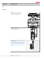
1
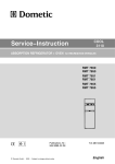
MAKING MODERN LIVING POSSIBLE
Service Manual
Steering Valve
OSPE
powersolutions.danfoss.com
Service Manual
OSPE Steering Valve
Revision history
Table of revisions
2
Date
Changed
Rev
August 2015
Codenumber changed
0001
February 2015
First edition
AA
L1506577 • Rev 0001 • August 2015
Service Manual
OSPE Steering Valve
Contents
Safety Precautions
Service Literature
Exploded View and Seal Kit
Tools
Dismantling
Assembly
Safety Precautions............................................................................................................................................................................4
Symbols Used in Danfoss Literature..........................................................................................................................................5
OSPE versions.....................................................................................................................................................................................5
OSPE exploded view........................................................................................................................................................................6
OSPE parts list.................................................................................................................................................................................... 7
Tools for OSPE................................................................................................................................................................................. 10
Dismantling OSPE.......................................................................................................................................................................... 12
Assembling OSPE........................................................................................................................................................................... 26
Test and valve setting of OSPE
Set up for testing............................................................................................................................................................................42
Set up OSPE with integrated priority valve..................................................................................................................... 42
Set up OSPE without integrated priority valve.............................................................................................................. 43
Steering test.....................................................................................................................................................................................43
Pilot relief valve...............................................................................................................................................................................44
Neutral positioning test, OSP part........................................................................................................................................... 44
Neutral positioning test, EH part.............................................................................................................................................. 44
Manual steering..............................................................................................................................................................................44
Shock valves.....................................................................................................................................................................................44
OSPE LSRM.................................................................................................................................................................................. 44
OSPE LS (non reaction/non reaction versions).............................................................................................................. 44
Check for external leakage......................................................................................................................................................... 45
Tightening Torques
Tightening torques for connections OPSE............................................................................................................................46
L1506577 • Rev 0001 • August 2015
3
Service Manual
OSPE Steering Valve
Safety Precautions
Safety Precautions
Always consider safety precautions before beginning a service procedure. Protect yourself and others
from injury. Take the following general precautions whenever servicing a hydraulic system.
W
Warning
Unintended Machine Movement
Unintended movement of the machine or mechanism may cause injury to the technican or bystanders.
To prevent uintended movement, secure the machine or disable / disconnect the mechanism while
servicing.
W
Warning
Flammable Cleaning Solvents
Some cleaning solvents are flammable. To eliminate the risk of fire, do not use cleaning solvents in an
area where a source of ignition may be present.
W
Warning
Fluid under Pressure
Escaping hydraulic fluid under pressure can have sufficient force to penetrate your skin causing serious
injury and/or infection. This fluid may also be hot enough to cause burns. Use caution when dealing with
hydraulic fluid under pressure. Relieve pressure in the system before removing hoses, fittings, gauges, or
components. Never use your hand or any other body part to check for leaks in a pressurized line. Seek
medical attention immediately if you are cut by hydraulic fluid.
W
Warning
Personal Safety
Protect yourself from injury. Use proper safety equipment, including safety glasses, at all times.
W
Warning
Product Safety
Steering valves are safety components and therefore it is extremely important that the greatest care is
taken when servicing these products. There is not much wear on a steering valve and therefore they
normally outlast the application they are built into. Therefore the only recommended service work on
steering valves is:
• Changing seals and o-rings
• Disassemble, clean and assemble if contaminated
• Make hydraulic testing including valve setting.
4
L1506577 • Rev 0001 • August 2015
Service Manual
OSPE Steering Valve
Service Literature
Symbols Used in Danfoss Literature
•
•
•
•
•
•
•
•
•
•
= Non removable part, use a new part
= External hex head
= Internal hex head
= Lubricate with hydraulic fluid
= Inspect for wear or damage
= Note correct orientation
= Mark orientation for reinstallation
= Torque specification
= Press in - press fit
= Pull out with tool - press fit
OSPE versions
This service literature is valid for:
All OSPE’s with single stage gear set
All OSPED with dual gear set. For the gear set end however only for V2/OSPED in new design
•
•
If the OSPED in question is in “old” or “V2/new” design can be traced by the product code:
OSPED’s with product code number higher than 11113069 are all in “new” design
•
•
OSPED’s with product code lower than 11113069 are all in “old” design
For further explanations between OSPED in “old” and “new” design, see Product Information Bulletin
ST2014-0139.
Service literature HN.21.ZA.52 is valid for gear set end of OSPED in “old” version.
L1506577 • Rev 0001 • August 2015
5
Service Manual
OSPE Steering Valve
Exploded View and Seal Kit
OSPE exploded view
34
30
120
116
122
39
117
115
93
300
301
302
36
35
95
31
7
18
27
14
303
304
305
16
34
OSPED
39
30
12
1
205
310
36
209
35
31
202
311
13
40
253
254
9
OSPE
64
62
61
63
41
3
222
242
221
241
224
312
225
6
330
331
87
332
81
86
5
80
85
321
4
DEUTSCH
246
243
322
323
247
230
213
249
214
203
215
247
314
232
231
320
AMP
248
216
312
204
207
313
312
CLS
233
207
204
204
AMP
233
DEUTSCH
233
6
L1506577 • Rev 0001 • August 2015
P301 786
Service Manual
OSPE Steering Valve
Exploded View and Seal Kit
OSPE parts list
OSPE parts list
OSPE
Number per unit Item
Tigtening
torque
Spool/Sleeve set
1
1
-
Housing
1
3
-
Screw
1
4
1.5 ±0.3 Nm
Ball for emergency steering Ø8.5 mm
1
5
-
O-ring Ø79.4 x Ø2.0 mm
1
6
-
Shaft seal
1
7
-
Dust seal ring
1
9
-
Cross pin
1
12
-
Cardan sharft
1
13
-
Set of springs
1
14
-
Ring
1
16
-
Bearing assembly
1
18
-
Gear set
1
30
-
Short screw (OSPED)
1
27
30 ±6 Nm
Screws (OSPED)
6
31
30 ±6 Nm
Screws (OSPE)
7
31
30 ±6 Nm
Valve plate
1
34
-
Washers
7
35
-
End cover
1
36
-
O-ring Ø79.4 x Ø2.0 mm (OSPED)
6
39
-
O-ring Ø79.4 x Ø2.0 mm (OSPE)
2
39
-
O-ring Ø9.0 x Ø1.5 mm
2
40
-
O-ring Ø6.0 x Ø1.5 mm
2
41
-
Balls for shock valves Ø4.8 mm
2
61
-
Spring with thrust pad for shock valves
2
62
-
Valves seats
2
63
5.5 ±0.5 Nm
Adjusting screws for shock valves
2
64
-
Pins
2
80
3 ±0.5 Nm
Balls for suction valves Ø4.8 mm
2
81
-
Screw
1
85
1.5 ±0.3 Nm
Spring
1
86
-
Valve cone for P check
1
87
-
Plug
1
93
-
Pilot relief valve cartridge
1
95
20 ±3 Nm
Gear set
1
115
-
Valve plate
1
116
-
Valve plate
1
117
-
Cardan shaft
1
120
-
Valve housing assembly
1
122
-
Spool, EH steering
1
202
-
Spool priority valve
1
203
-
PVE
1
204
-
Plug
1
205
45 ±5 Nm
L1506577 • Rev 0001 • August 2015
7
Service Manual
OSPE Steering Valve
Exploded View and Seal Kit
OSPE parts list (continued)
8
OSPE
Number per unit Item
Tigtening
torque
Plug
1
207
45 ±5 Nm
Plugs
2
209
45 ±5 Nm
Spring
1
213
-
Cone pilot supply
1
214
-
Spool pilot supply
1
215
-
Plug
1
216
30 ±3 Nm
Check valve, LS
1
221
3.5 ±0.5 Nm
Orifice, LS
1
222
3.5 ±0.5 Nm
Spool pvfc
1
224
-
Plug
1
225
15 ±2 Nm
Orifice PP
1
230
3.5 ±0.5 Nm
Spring
1
231
-
Orifice Dynamic
1
232
1 ±0.1 Nm
Screws
4
233
8 ±1 Nm
Spring
1
241
-
Spool reaction/EH L&R cut off
1
242
-
Plug
1
243
45 ±5 Nm
Cartridge spool, pilot dump
1
246
15 ±2 Nm
Coil
1
247
-
Nut
1
248
5 ±1 Nm
O-ring Ø10.0 x Ø1.5 mm
1
249
-
Plug
1
253
20 ±3 Nm
Plug
1
254
20 ±3 Nm
Lock ring
1
300
-
O-ring Ø7.5 x Ø1.5 mm
1
301
-
O-ring Ø11.0 x Ø2.0 mm
1
302
-
Backup ring
1
303
-
O-ring Ø8.0 x Ø1.5 mm
1
304
-
Filter
1
305
-
O-ring Ø23.3 x Ø2.4 mm
1
310
-
O-ring Ø17.8 x Ø2.1 mm
2
311
-
O-ring Ø17.4 x Ø2.1 mm
2
312
-
O-ring Ø15.0 x Ø1.5 mm
1
313
-
O-ring Ø11.0 x Ø2.0 mm
1
314
-
O-ring Ø10.0 x Ø2.0 mm
3
320
-
O-ring Ø30.0 x Ø2.5 mm
1
321
-
O-ring Ø8.0 x Ø2.0 mm
1
322
-
Filter
1
323
-
O-ring ø7.65 x ø1.78 mm
1
330
-
O-ring ø9.25 x ø1.78 mm
1
331
-
O-ring ø13.5 x ø2.08 mm
1
332
-
L1506577 • Rev 0001 • August 2015
Service Manual
OSPE Steering Valve
Exploded View and Seal Kit
OSPE seal kit and spare parts
Spare parts list
Code No.
Item
Coil, Deutsch®: D08 12V DE 322113
11084688
247
Coil, AMP: D08 12V AJE 321930
11084690
247
Spare part bag containing:
Cartridge spool for pilot dump, Nut and O-ring
11085713
246, 248, 249
Seal kit OSPE steering unit part
150N4041
6, 7, 9, 35, 39, 40, 41
Seal kit OSPE EH part
11160415
93, 225, 310, 311, 312, 313, 314
Seal kit Pilot relief valve cartridge
155L6870
300, 301, 302, 303, 304, 305
Seal kit PVE
157B4997
320, 321, 322, 323
Seal kit Cartridge spool for pilot dump
120433
330, 331, 332
Spare parts list
Code No.
Containing seal kits, codes
Seal kit KIT OSPE complete
11160838
150N4041, 11160415, 155L6870,
157B4997, 120433
L1506577 • Rev 0001 • August 2015
9
Service Manual
OSPE Steering Valve
Tools
Tools for OSPE
Tools
120±2
5±1
90±1
1x45˚
20±1
Holding tool for the entire steering valve.
Material: Appropriate metal or hard plastic
This tool is not available from Danfoss.
2xø15±0.1
ø46±0.5
90±1
100±2
ø6
4
-0
.5/
+0
5
ø1
7x
7x51.4˚
93±0.5
150±2
P301 787
min 35
100±5
Assembly tool for dust seal.
Material: Free cutting steel.
This tool is not available from Danfoss.
0.5x45°
ø26±0.1
min ø40
Assembly tool for shaft seal, O-ring/Roto Glyd type: Code
number: 11092408.
This tool has been modified by January 2015. The upper
end of outer tube has knurled surface on 25 mm from top
only (was 35 mm). Tool with 35 mm knurled surface can
be modified by grinding off 10 mm of the knurled
surface.
10
L1506577 • Rev 0001 • August 2015
P301 643
Service Manual
OSPE Steering Valve
Tools
Tools (continued)
Tool for removing/assembling pilot relief valve cartridge:
Code number: 155L6494
Torque wrench 0 - 70 Nm.
13 – 17 - 19 and 32 mm socket spanner.
2 - 2.75 – 3 – 4 – 5 – 6 and 8 mm Hex key.
12 mm screwdriver.
2 mm screwdriver.
13 – 17 – 19 – 7/8 inch mm ring spanner.
Inside circlip pliers
Plastic hammer.
Tweezers.
These tools are not available from Danfoss.
L1506577 • Rev 0001 • August 2015
11
Service Manual
OSPE Steering Valve
Dismantling
Dismantling OSPE
Dismantling OSPE
Place the unit in the holding tool on steering column
end.
Screw out the 4 screws for the PVE (233) using a 5 mm
Hex key.
Remove the PVE (204).
O-rings (320, 321, 322) and filter (323) are fitted to the
mounting surface of PVE.
Screw out the plug (243) using a 17 mm
ring spanner.
O-ring (312) is fitted on plug (243).
Remove the spring (241).
12
L1506577 • Rev 0001 • August 2015
socket or
Service Manual
OSPE Steering Valve
Dismantling
Dismantling OSPE (continued)
Remove the EH L&R cut off spool (242).
Screw out the plug (207).
If the OSPE is with priority valve integrated:
Use a 17 mm
socket or ring spanner. O-ring (312) is
fitted on plug (207).
If the OSPE is without priority valve integrated:
Use a 8 mm
Hex key. This plug is fitted with O-ring
(312) and (313).
Remove the spring (231).
Remove the priority valve spool (203).
Orifices (230) and (232) are screwed into spool (203).
L1506577 • Rev 0001 • August 2015
13
Service Manual
OSPE Steering Valve
Dismantling
Dismantling OSPE (continued)
Screw off the nut (248) using a 19 mm
spanner.
socket or ring
Remove the O-ring (249).
Lift off the coil (247).
Screw out the cartridge spool (246) using a 7/8 inch
ring spanner. O-rings (330, 331, 332) are fitted on
cartridge spool (246).
14
L1506577 • Rev 0001 • August 2015
Service Manual
OSPE Steering Valve
Dismantling
Dismantling OSPE (continued)
Replace the unit in the holding tool on the gear set end.
Use appropriate support made of plastic, brass or
aluminum under the mounting surface for the PVE to
support the steering valve.
Screw out the adjusting screws for shock valves (64)
using a 5 mm
Hex key.
O-ring (40) is fitted on screw (64)
Remove the springs with trust pads for shock valves (62).
Remove the balls for shock valves (61).
L1506577 • Rev 0001 • August 2015
15
Service Manual
OSPE Steering Valve
Dismantling
Dismantling OSPE (continued)
Screw out the seats for shock valves (63) using a 2.75 mm
Hex key.
O-ring (41) is fitted on seat (63).
Screw out the plug (205) using a 32 mm
spanner.
O-ring (310) is fitted on plug (205).
socket
Remove the EH-spool (202).
Screw out the plugs (209) using an 8 mm
O-ring (311) is fitted on plug (209)
Hex key.
The left side positioned plug is only present on OSPE’s
with priority valve integrated.
Replace the unit in the holding tool on steering column
end.
16
L1506577 • Rev 0001 • August 2015
Service Manual
OSPE Steering Valve
Dismantling
Dismantling OSPE (continued)
Remove the plug (93) for the pilot relief valve (95)
Screw out the pilot relief valve cartridge (95) using special
key Danfoss code 155L6494.
Screw out the orifice (222) using a 3 mm
Hex key.
This orifice is not present in all OSPE’s.
L1506577 • Rev 0001 • August 2015
17
Service Manual
OSPE Steering Valve
Dismantling
Dismantling OSPE (continued)
Screw out the LS check valve (221) using a 3 mm
key.
Hex
This check valve is not present in all OSPE’s.
Screw out the plugs (253) and (254) using a 6 mm
Hex key.
These plugs not present in all OSPE’s.
OSPED:
Remove the screws (1x27 and 6x31) with washers (35)
using a 13 mm
socket or ring spanner.
OSPE:
Has 7 identical screws (7x 31).
Remove the end cover (36), sideways.
18
L1506577 • Rev 0001 • August 2015
Service Manual
OSPE Steering Valve
Dismantling
Dismantling OSPE (continued)
OSPED: Lift the gearwheel set (115) off the unit. Remove
the two O-rings (39).
OSPED: Remove the distributor plate (117).
OSPED: Remove valve housing assembly (122). Remove
the two O-rings (39).
Do not dismantle the entire valve (122).
OSPED: Remove the distributor plate (116).
L1506577 • Rev 0001 • August 2015
19
Service Manual
OSPE Steering Valve
Dismantling
Dismantling OSPE (continued)
OSPED: Remove the cardan shaft (120).
Lift the gearwheel set (30) off the unit. Remove the two
O-rings (39).
Remove the cardan shaft (13).
Remove the distributor plate (34) from the housing.
20
L1506577 • Rev 0001 • August 2015
Service Manual
OSPE Steering Valve
Dismantling
Dismantling OSPE (continued)
Remove the O-ring (6) from housing.
Screw out threaded bushing/ball stop (4) from housing
using a 12 mm screw driver and remove bushing from
housing.
Screw out the screw (85) using a 12 mm screw driver.
Spring (86) and valve cone (87) will be attached to the
screw (85).
L1506577 • Rev 0001 • August 2015
21
Service Manual
OSPE Steering Valve
Dismantling
Dismantling OSPE (continued)
Screw out the pin bolts (80) using a 4 mm
Screw out the plug (216) using a 6 mm
ring 314 is fitted on plug (216).
Remove plug (216) and spool (215).
22
L1506577 • Rev 0001 • August 2015
Hex key.
Hex key. O-
Service Manual
OSPE Steering Valve
Dismantling
Dismantling OSPE (continued)
Screw out the plug (225) using a 5 mm
Hex key.
Remove spool (224) using a 4 mm screw.
Shake out the check valve ball (5), suction valve balls (81),
cone (214) and spring (213).
Place the housing with the ports facing down on the
work bench. Ensure that the cross pin (12) in the spool
and sleeve set (1) is in the horizontal position. The pin
(12) can be observed through the open end of the spool.
L1506577 • Rev 0001 • August 2015
23
Service Manual
OSPE Steering Valve
Dismantling
Dismantling OSPE (continued)
Press the spool (1) inwards (from the steering column
end) and the sleeve (1), ring (16), neutral position springs
(14) and bearing assembly (18) will be pushed out of the
housing together.
Take the bearing races with needle bearing (18) and the
ring (16) off from the spool and sleeve set (1). The outer
bearing (18) race can sometimes “stick” in the housing,
therefore check that it has come out.
Press out the cross pin (12).
Carefully press the spool out of the sleeve.
24
L1506577 • Rev 0001 • August 2015
Service Manual
OSPE Steering Valve
Dismantling
Dismantling OSPE (continued)
Press the neutral position springs (14) out of the slot of
the spool.
Remove dust seal (9) and shaft seal (Roto Glyd) (7)
carefully with a screw driver or similar tool.
The steering unit OSPED is now completely dismantled
Cleaning Clean all parts carefully in Shellsol K or similar
cleaner fluid.
Inspection and replacement
Replace all seals and washers. Check all parts carefully
and make any replacements as is necessary.
L1506577 • Rev 0001 • August 2015
25
Service Manual
OSPE Steering Valve
Assembly
Assembling OSPE
Assembling OSPE
Place the two flat neutral position springs (from item 14)
in the slot of the spool (from item 1).
Place the curved springs between the flat ones and press
them into place.
Configuration of spring set (14).
There can be different numbers of curved springs
depending on configuration of spring set.
There can be 2, 4 or 6 curved springs.
150-386.10
OSPEF: Spool and sleeve must be positioned correctly
relatively to each other. Small marks are present on both
spool and sleeve close to one of the slots for the spring
set.
150-412.10
Guide the spool into the sleeve (1).
If the spool and sleeve has marks as shown above, these
must be placed on same side.
Make sure the neutral position springs (14) are placed
into the slot.
26
L1506577 • Rev 0001 • August 2015
Service Manual
OSPE Steering Valve
Assembly
Assembling OSPE (continued)
Line up the spring set (14).
Guide the ring (16) down over the sleeve.
The ring should be able to move free of the springs
Fit the cross pin (12) into the spool/sleeve set (1).
Fit bearing races and needle bearing (18) as shown on
the drawing below.
L1506577 • Rev 0001 • August 2015
27
Service Manual
OSPE Steering Valve
Assembly
Assembling OSPE (continued)
C
Caution
Assembly pattern for standard bearing
1. Outer bearing race
2. Needlebearing
3. Inner bearing race
4. Spool
5. Sleeve
* The inside chamfer on the inner bearing race must face
the chest of the inner spool.
Place the steering valve housing with the port face down
on the work bench. Guide the outer part of the assembly
tool into the bore for the spool/sleeve set (1).
Grease the shaft seal (Roto Glyd, 7) with hydraulic oil and
place them on the tool. Ensure that the Roto Glyd seal is
placed on the insertion tool as per the photograph.
Hold the outer part of the assembly tool in the bottom of
the steering unit housing and guide the inner part of the
tool right to the bottom.
28
L1506577 • Rev 0001 • August 2015
Service Manual
OSPE Steering Valve
Assembly
Assembling OSPE (continued)
Press and turn the shaft seal (7) into position in the
housing.
Draw the inner and outer parts of the assembly tool out
of the steering unit bore, leaving the guide from the
inner part in the bore.
With a light turning movement, guide the spool and
sleeve into the bore.
Fit the spool set holding the cross pin (12) horizontal.
The spool set will push out the assembly tool guide. The
shaft seal (7) is now installed.
Place the steering valve housing (3) on the holding tool
on the steering column end.
L1506577 • Rev 0001 • August 2015
29
Service Manual
OSPE Steering Valve
Assembly
Assembling OSPE (continued)
Put the check valve ball (5) into the hole indicated by the
circle.
Screw in the screw (4) using a 12 mm screw driver.
1.5 ±0.3 Nm.
Assemble spring (86) and cone (87 on screw (85).
Place the assembly in the hole indicated by the circle.
Screw in the screw (85) using a 12 mm screw driver.
1.5 ±0.3 Nm.
Put the suction valve balls (81) into the holes indicated by
the circles.
30
L1506577 • Rev 0001 • August 2015
Service Manual
OSPE Steering Valve
Assembly
Assembling OSPE (continued)
Screw in the pin bolts (80) using a 4 mm
3 ±0.5 Nm.
Hex key.
Place the spool (224) in the hole indicated by the circle.
Screw in the plug (225) using a 5 mm
±2 Nm
L1506577 • Rev 0001 • August 2015
Hex key.
10
31
Service Manual
OSPE Steering Valve
Assembly
Assembling OSPE (continued)
Place the spring (213), cone (214) and spool (215) in the
hole indicated by the circle.
Place the O-ring (314) on plug (216). Screw in the plug
(216) using a 6 mm
32
Hex key.
L1506577 • Rev 0001 • August 2015
30 ±3 Nm.
Service Manual
OSPE Steering Valve
Assembly
Assembling OSPE (continued)
Insert the O-ring (6) in the grove on the housing.
Place the distributor plate (34).
OSPED: the small ø4 mm hole of the plate (34) must be
placed above the ø3 mm hole in the housing The radial
channel groove of the plate (34) must be facing the
housing side.
Guide the cardan shaft (13) down into the bore so that
the slot is parallel with the connection flange for P, T, L
and R ports and lines up with the cross pin (12).
Place the 2 O-rings (39) in the two groves in the gear rim.
Fit the gearwheel with rim (30) on the cardan shaft (13).
Place the gear wheel side with all the deeper splines
facing downwards. Only this side will fit on the cardan
shaft due to all gear sets used in OSPE have timing
securing: splines of gear wheel and cardan shaft can only
be assembled with correct timing.
L1506577 • Rev 0001 • August 2015
33
Service Manual
OSPE Steering Valve
Assembly
Assembling OSPE (continued)
OSPED: Place and rotate the cardan shaft (120) with the
big diameter end until it moves in gear with gear wheel
of gear set (30).
OSPED: Place the middle distributor plate (116) so that
the channel holes match the holes in the gear set.
OSPED: Place the 2 O-rings (39) in the two groves in the
valve housing assembly (122). Place the valve housing
assembly so that the one and only M8 thread whole
points upwards and direction port face for P, T, L and R
connections.
Make sure that channel holes of the valve housing
assembly (122) match the holes in the distributor plate
(116).
34
L1506577 • Rev 0001 • August 2015
Service Manual
OSPE Steering Valve
Assembly
Assembling OSPE (continued)
OSPED: Place the rear distributor plate (117) so that the
channel holes match the holes in valve housing assembly
(122).
OSPED: Place the 2 O-rings (39) in the two groves in the
gear rim. Fit the gearwheel with rim (115) on the cardan
shaft (120).
Place the gear wheel side with all the deeper splines
facing downwards. Only this side will fit on the cardan
shaft due to all gear sets used in OSPE have timing
securing: splines of gear wheel and cardan shaft can only
be assembled with correct timing.
Place the end cover (36) in position. Ensure that the bar
codes and writing are parallel with the port face for P, T, L
and R connections.
OSPED: Fit the short screw (27) with washer (35) and
place it in the hole indicated by circle.
OSPED: Fit the six screws (31) with new washers (35) and
insert them.
Cross-tighten all the screws (27 and 31) using a 13 mm
socket spanner.
30 ±6 Nm.
OSPE: Has 7 identical screws (7x 31).
Replace the unit in the holding tool on gear set end. Use
appropriate support under the mounting surface for the
PVE to support the steering valve.
L1506577 • Rev 0001 • August 2015
35
Service Manual
OSPE Steering Valve
Assembly
Assembling OSPE (continued)
The OSPE can now be function tested manually: it must
be possible to rotate input shaft with torque < 3.5 Nm [31
lbf•in].
Place the dust seal ring (9) in the housing.
Fit the dust seal ring (9) in the housing using special tool
for dust seal assembly (see page 7) and a plastic
hammer.
Place O-ring (41) on the shock valve seats (63). Screw in
the seats (63) using a 2.75 mm
cavities indicated by the circles.
8.85 lbf•in].
Hex key into the
6 ± 1 Nm. [53.1 ±
Place one ball (61) in each of the shock valve cavities.
36
L1506577 • Rev 0001 • August 2015
Service Manual
OSPE Steering Valve
Assembly
Assembling OSPE (continued)
Place springs with trust pads (62) over the two balls.
Place O-rings (40) on adjusting screws (64). Screw in the
two adjusting screws (64) using a 5 mm
Hex key.
After entire assembly of the steering valve, make the
pressure setting on a test panel according to valve
setting specification, see Shock valves on page 44.
Insert the EH-spool (202).
Place O-ring (310) on plug (205). Screw in the plug (205)
using a 32 mm
socket spanner.
L1506577 • Rev 0001 • August 2015
45 ±5 Nm
37
Service Manual
OSPE Steering Valve
Assembly
Assembling OSPE (continued)
Place O-rings (311) on plugs (209). Screw in the plugs
(209) using a 8 mm
Hex key.
45 ±5 Nm
The left side positioned plug is only present on OSPE’s
with priority valve integrated.
Replace the unit in the holding tool on steering column
end.
Place back up ring (303), O-rings (301, 302, 304), filter
(305) and locking ring (300) in/on cartridge (95). Screw in
cartridge (95) using special key Danfoss code 155L6494.
20 ±3 Nm.
After entire assembly of the steering valve, make the
pressure setting on a test panel according to valve
setting specification, see Shock valves on page 44.
Insert plastic protection plug (93).
Screw in the LS check valve (221) using a 3 mm
key.
Hex
3 ±0.5 Nm.
This check valve is not present in all OSPE’s.
Screw in the orifice (222) using a 3 mm
3 ±0.5 Nm.
This orifice is not present in all OSPE’s.
38
L1506577 • Rev 0001 • August 2015
Hex key.
Service Manual
OSPE Steering Valve
Assembly
Assembling OSPE (continued)
Screw in the plugs (253) and (254) using a 6 mm
key.
Hex
20 ±3 Nm.
These plugs not present in all OSPE’s.
Place O-rings (330, 331, 332) on cartridge spool (246).
Screw in the cartridge spool (246) using a 7/8 inch
ring spanner.
15 ±2 Nm.
OSPE with priority valve: Assemble spool (203) with the
PP orifice (230) using a 3 mm
Hex key.
3.5 ±0.5
Nm. And with dynamic orifice (232) using a 2 mm
Hex key.
1 ±0.1 Nm. Insert the priority valve spool
(203) with the spring bore pointing outwards.
OSPE with priority valve:
Insert the spring (231). Dimension of this spring depends
on specification of priority valve.
L1506577 • Rev 0001 • August 2015
39
Service Manual
OSPE Steering Valve
Assembly
Assembling OSPE (continued)
OSPE with priority valve:
Place the O-ring (312) on plug (207 with 17 mm key
profile).
Screw in the plug (207) using a 17 mm
socket
spanner
45 ±5 Nm.
OSPE without priority valve:
Place the O-rings (312, 313) on plug (207 with 8 mm
Hex key profile).
Screw in the plug (207) using a 8 mm
Hex key.
45 ±5 Nm.
Insert the EH L&R cut off spool (242) with the spring bore
pointing outwards.
Insert the spring (241). Dimension of this spring: Wire
diameter: 2.2 mm Length: 50.2 ±0.8 mm
Place the O-ring (312) on plug (243). Screw in the plug
(243) using a 17 mm
40
socket spanner
L1506577 • Rev 0001 • August 2015
45 ±5 Nm.
Service Manual
OSPE Steering Valve
Assembly
Assembling OSPE (continued)
Check proper movement of EH spool (202): press on
spool end, the spool must be able to be moved
downwards 4 mm with force < 100N, and it must be able
to return to starting position by help of the neutral spring
package integrated in the spool end facing plug (205).
Place O-rings (320, 321, 322) and filter (323) on PVE (204).
Place the PVE (204) on OSPE housing as illustrated and
screw in the 4 screws for the PVE (233) using a 5 mm
Hex key.
8 ±1 Nm.
Place coil 247 on cartridge for pilot dump (246). Place Oring (249) and nut (248) on cartridge for pilot dump (246).
Screw in the nut (248) using a 19 mm
socket spanner
5 ±1 Nm.
Make test and valve setting according to description,
seeSteering test on page 43.
Screw in the plastic plugs into the connection ports to
keep the ports clean during storage and transportation.
L1506577 • Rev 0001 • August 2015
41
Service Manual
OSPE Steering Valve
Test and valve setting of OSPE
This section describes minimum tests needed, when the OSPE steering valve has been disassembled and
reassembled.
OSPEDC LSRM with integrated priority valve:
OSP
L
Rr
Lr
R
LS
P
EH
PVE
Electronics
PE
TE
LS
P
EF
T
L
R
P301 171
Set up for testing
A universal hydraulic work bench is required for this setup. The work bench must support the following
pump capacity.
• 25 l/min and up to 210 bar pressure for relief valve setting and steering test
• 3 l/min and up to 280 bar pressure for shock valve setting
The hydraulic oil must have a viscosity of 21 cSt. at 50°C with a maximum degree of contamination
according to ISO 4406: 21/19/16.
Set up OSPE with integrated priority valve
1. Connect double rod cylinder to L and R ports of OSPE.
2. Connect pressure gauges to all ports of OSPE.
3. Connect steering column and steering wheel to the input shaft of the OSPE.
42
L1506577 • Rev 0001 • August 2015
Service Manual
OSPE Steering Valve
Test and valve setting of OSPE
4. If OSPE with PVES, PVED CC, or PVED CL, connect battery power cables with on/off switch to the coil
of control valve for mode select (247).
Voltage must meet the specification for the code.
For OSPE with PVED CLS, the coil (247) is controlled by the PVED CLS.
5. Connect voltage supply and signal input for the PVE.
6. Connect P port to pump supply.
7. Block LS port with steel plug.
8. Connect T and EF ports separately to tank of pump station.
T pressure should not exceed ~5 bar. The maximum allowed T pressure is 25 bar.
The pump supply circuit should not exceed 210 bar P-T.
9. Screw the adjusting screws of shock valves to block.
Screw clockwise as much as possible to a torque < 5 Nm to ensure the shock valves do not open
during steering test or setting of pilot relief valve.
Set up OSPE without integrated priority valve
1. Connect double rod cylinder to L and R ports of OSPE.
2. Connect pressure gauges to all ports of OSPE.
3. Connect steering column and steering wheel to the input shaft of the OSPE.
4. If OSPE with PVES, PVED CC, or PVED CL, connect battery power cables with on/off switch to the coil
of control valve for mode select (247).
Voltage must meet the specification for the code.
For OSPE with PVED CLS, the coil (247) is controlled by the PVED CLS.
5. Connect voltage supply and signal input for the PVE.
6. Connect an external priority valve between P of pump station and P of OSPE.
Use Danfoss priority valve OLS 80 code 152B8269, or other OLS 80 with same orifice and spring
specification.
Dynamic orifice: Ø1,0 mm
LS orifice: Ø1,2 mm
Spring: 7 bar
7. Connect LS port of OSPE with LS port of OLS.
8. Connect T port of OSPE to tank.
9. Screw the adjusting screws of shock valves to block.
Screw clockwise as much as possible to a torque < 5 Nm to ensure the shock valves do not open
during steering test or setting of pilot relief valve.
Steering test
During the testing no motor effect, disturbing vibrations, noise, sticking or other irregularities must occur.
1. Start the pump, the pump flow is adjusted to approx. 25 l/min and pump pressure control must be
set to app. 70 bar.
2. Let the supplied oil flow through the steering unit for a few minutes. At the same time the steering
wheel is to be rotated a few times in both directions to bleed of air from the unit and the system.
3. Operate the steering wheel by approx. 10 rpm in a smooth manner from end stroke to end stroke of
the steering cylinder for at least 5 cycles. Make sure pressure P-T, 70 bar can be achieved, when
steering against end stroke. If this is not possible, the adjusting screw of the pilot relief valve (item 95
of exploded view) must be turned clockwise until P-T, 70 bar is achievable.
L1506577 • Rev 0001 • August 2015
43
Service Manual
OSPE Steering Valve
Test and valve setting of OSPE
Pilot relief valve
The pump flow is adjusted to approx. 25 l/min and pressure to max 210 bar.
The steering wheel is actuated until the steering cylinder reaches one of its end strokes and the steering
wheel is actuated in this cylinder position with steering torque 25 ±5 Nm.
The pilot relief valve (item 95 of exploded view) is set according to specification: Maximum steering
pressure (P-T), bar, for the code in question.
The setting pressure is the pressure on the P-port minus the T-port of OSPE.
Neutral positioning test, OSP part
After adjusting the pilot relief valve, the steering wheel must be able to go to neutral position by itself no
later than ~1 second after the activation of the steering wheel has been stopped.
The steering unit is in neutral position when the pressure drop (P-T) is no higher than 18 bar.
Neutral positioning test, EH part
For OSPE with PVES, PVED CC, PVED CL: Apply battery power to the coil (item 247 on exploded view).
Apply battery power and input signal to the PVE: observe that the steering cylinder is moving according
to direction of input signal for PVE. Apply neutral position signal for PVE, observe that cylinder movement
stops and that pressure LS-T drops to max. 10 bar.
For OSPE with PVED CLS: The coil (item 247 of exploded view) is controlled by the PVED CLS.
Manual steering
Without pressure on P and T ports, the unit must be able to steer in a smooth manner to the right and to
the left observed by the cylinder movement.
For OSPED: the number of turns on the steering wheel for moving the steering cylinder from lock to lock,
must increase in comparison to do this test with normal pump supply. Without pump supply the number
of turns must match cylinder volume/emergency steer displacement of OSPED. Example: Cylinder
volume: 600 ccm, and OSPED 60/185 LSRM > Number of turns must be 600/60 ~ = 10 turns.
Shock valves
Remove pump supply to P port of OSPE and plug the P-port. Remove the steering cylinder
connection. T must still be connected to tank of pump station.
OSPE LSRM
L and R ports are connected through the spool/sleeve set in neutral, steering wheel must be untouched
during setting of shock valves:
1. Plug the L- port and apply pump pressure to the R-port. The shock valves are to be set at an oil flow of
3 l/min. The supply must be limited to max 280 bar on the pump station.
2. Screw one of the shock valves (item 64) outwards until pressure is reduced to the lower specified
value + 15-20 bar and flows comes out of the T-port (e.g. 235-240 bar of specified value 220-240 bar)
3. Screw the other shock valve (item 64) outwards until pressure is reduced to the lower specified value
+ 0-5 bar and check that flow out of T-port continues (e.g. 220-225 bar of specified value 220-240
bar).
OSPE LS (non reaction/non reaction versions)
The shock valves are to be set at an oil flow of 3 l/min applied to one of the servo ports L and R at a time.
The supply must be limited to maximum 280 bar on the pump station.
44
L1506577 • Rev 0001 • August 2015
Service Manual
OSPE Steering Valve
Test and valve setting of OSPE
Adjust the pressure (R-T/L-T) by adjusting screws of shock valves (item 64) to the specified value for the
shock valve setting for the code in question.
Check for external leakage
After testing of the former items, the steering column (wheel) and port connections are removed. P, L, R,
EF and LS ports are to be plugged and oil pressure of 20 bar is supplied to the T port for approx. 3
minutes: No leakage must be found in any assemblies or at the input shaft for the steering column.
L1506577 • Rev 0001 • August 2015
45
Service Manual
OSPE Steering Valve
Tightening Torques
Tightening torques for connections OPSE
Tightening Torques for Connections OSPD V2
Connections
46
Maximum tightening torque Nm [lbf.in]
With cutting edge
With copper washer With alum. Washer
O-ring
M12 • 1.5
30 [265]
20 [177]
30 [265]
25 [221]
M18 • 1.5
80 [708]
55 [486]
70 [619]
50 [442]
M22 • 1.5
100 [885]
65 [575]
80 [708]
60 [531]
L1506577 • Rev 0001 • August 2015
Service Manual
OSPE Steering Valve
L1506577 • Rev 0001 • August 2015
47
Products we offer:
•
•
•
•
•
•
•
•
•
•
•
•
•
•
•
•
Bent Axis Motors
Closed Circuit Axial Piston
Pumps and Motors
Displays
Electrohydraulic Power
Steering
Electrohydraulics
Danfoss Power Solutions is a global manufacturer and supplier of high-quality hydraulic and
electronic components. We specialize in providing state-of-the-art technology and solutions
that excel in the harsh operating conditions of the mobile off-highway market. Building on
our extensive applications expertise, we work closely with our customers to ensure
exceptional performance for a broad range of off-highway vehicles.
We help OEMs around the world speed up system development, reduce costs and bring
vehicles to market faster.
Danfoss – Your Strongest Partner in Mobile Hydraulics.
Hydraulic Power Steering
Go to www.powersolutions.danfoss.com for further product information.
Integrated Systems
Wherever off-highway vehicles are at work, so is Danfoss. We offer expert worldwide support
for our customers, ensuring the best possible solutions for outstanding performance. And
with an extensive network of Global Service Partners, we also provide comprehensive global
service for all of our components.
Joysticks and Control
Handles
Microcontrollers and
Software
Open Circuit Axial Piston
Pumps
Orbital Motors
Please contact the Danfoss Power Solution representative nearest you.
PLUS+1® GUIDE
Proportional Valves
Sensors
Steering
Transit Mixer Drives
Comatrol
www.comatrol.com
Schwarzmüller-Inverter
www.schwarzmuellerinverter.com
Local address:
Turolla
www.turollaocg.com
Hydro-Gear
www.hydro-gear.com
Daikin-Sauer-Danfoss
www.daikin-sauer-danfoss.com
Danfoss
Power Solutions (US) Company
2800 East 13th Street
Ames, IA 50010, USA
Phone: +1 515 239 6000
Danfoss
Power Solutions GmbH & Co. OHG
Krokamp 35
D-24539 Neumünster, Germany
Phone: +49 4321 871 0
Danfoss
Power Solutions ApS
Nordborgvej 81
DK-6430 Nordborg, Denmark
Phone: +45 7488 2222
Danfoss
Power Solutions Trading
(Shanghai) Co., Ltd.
Building #22, No. 1000 Jin Hai Rd
Jin Qiao, Pudong New District
Shanghai, China 201206
Phone: +86 21 3418 5200
Danfoss can accept no responsibility for possible errors in catalogues, brochures and other printed material. Danfoss reserves the right to alter its products without notice. This also applies to
products already on order provided that such alterations can be made without changes being necessary in specifications already agreed.
All trademarks in this material are property of the respective companies. Danfoss and the Danfoss logotype are trademarks of Danfoss A/S. All rights reserved.
L1506577 • Rev 0001 • August 2015
www.danfoss.com
© Danfoss A/S, 2015