1
User Manual for the
HE300RSL100
HE300GEN100
Option Cards for
GE Drives AF-300E$
Adjustable Frequency Drives
Fourth Edition
09 August 2000
MAN0017-04
MAN0017-04
09 AUG 2000
PAGE 3
PREFACE
This manual explains how to use the Horner APG Communications Option Cards for use with the GE
Drives Adjustable Frequency Drives.
Copyright (C) 2000 Horner APG, LLC., 640 North Sherman Drive Indianapolis, Indiana 46201. All rights
reserved. No part of this publication may be reproduced, transmitted, transcribed, stored in a retrieval
system, or translated into any language or computer language, in any form by any means, electronic,
mechanical, magnetic, optical, chemical, manual or otherwise, without the prior agreement and written
permission of Horner APG, LLC.
All software described in this document or media is also copyrighted material subject to the terms and
conditions of the Horner Software License Agreement.
Information in this document is subject to change without notice and does not represent a commitment on
the part of Horner APG, LLC.
Genius, Series 90 and Logicmaster are trademarks of GE Fanuc Automation North America Inc.
For user manual updates, contact Horner APG, Technical Support
Division, at (317) 916-4274 or visit our website at www.heapg.com.
PAGE 4
09 AUG 2000
MAN0017-04
LIMITED WARRANTY AND LIMITATION OF LIABILITY
Horner APG, LLC. ("HE-APG") warrants to the original purchaser that the Option Card manufactured by
HE-APG is free from defects in material and workmanship under normal use and service. The obligation
of HE-APG under this warranty shall be limited to the repair or exchange of any part or parts which may
prove defective under normal use and service within two (2) years from the date of manufacture or
eighteen (18) months from the date of installation by the original purchaser whichever occurs first, such
defect to be disclosed to the satisfaction of HE-APG after examination by HE-APG of the allegedly
defective part or parts. THIS WARRANTY IS EXPRESSLY IN LIEU OF ALL OTHER WARRANTIES
EXPRESSED OR IMPLIED INCLUDING THE WARRANTIES OF MERCHANTABILITY AND FITNESS
FOR USE AND OF ALL OTHER OBLIGATIONS OR LIABILITIES AND HE-APG NEITHER ASSUMES,
NOR AUTHORIZES ANY OTHER PERSON TO ASSUME FOR HE-APG, ANY OTHER LIABILITY IN
CONNECTION WITH THE SALE OF THIS OPTION CARD. THIS WARRANTY SHALL NOT APPLY TO
THIS OPTION CARD OR ANY PART THEREOF WHICH HAS BEEN SUBJECT TO ACCIDENT,
NEGLIGENCE, ALTERATION, ABUSE, OR MISUSE.
HE-APG MAKES NO WARRANTY
WHATSOEVER IN RESPECT TO ACCESSORIES OR PARTS NOT SUPPLIED BY HE-APG. THE
TERM "ORIGINAL PURCHASER", AS USED IN THIS WARRANTY, SHALL BE DEEMED TO MEAN
THAT PERSON FOR WHOM THE OPTION CARD IS ORIGINALLY INSTALLED. THIS WARRANTY
SHALL APPLY ONLY WITHIN THE BOUNDARIES OF THE CONTINENTAL UNITED STATES.
In no event, whether as a result of breach of contract, warranty, tort (including negligence) or otherwise,
shall HE-APG or its suppliers be liable of any special, consequential, incidental or penal damages
including, but not limited to, loss of profit or revenues, loss of use of the products or any associated
equipment, damage to associated equipment, cost of capital, cost of substitute products, facilities,
services or replacement power, down time costs, or claims of original purchaser's customers for such
damages.
To obtain warranty service, return the product to your distributor with a description of the
problem, proof of purchase, post paid, insured and in a suitable package.
ABOUT PROGRAMMING EXAMPLES
Any example programs and program segments in this manual or provided on accompanying diskettes are
included solely for illustrative purposes. Due to the many variables and requirements associated with any
particular installation, Horner APG cannot assume responsibility or liability for actual use based on the
examples and diagrams. It is the sole responsibility of the system designer utilizing the product to
appropriately design the end system, to appropriately integrate the Drive Communications Card and to
make safety provisions for the end equipment as is usual and customary in industrial applications as
defined in any codes or standards which apply.
Note: The programming examples shown in this manual are for illustrative
purposes only. Proper machine operation is the sole responsibility of the
system integrator.
MAN0017-04
09 AUG 2000
PAGE 5
Revisions to This Manual
This version (MAN0017-04) of the Drive Communications Card User Manual contains the following
revisions, additions and deletions:
1. Converted manual into Word format.
2. Changed company name from Horner Electric, Inc. to Horner APG, LLC.
PAGE 6
09 AUG 2000
NOTES
MAN0017-04
MAN0017-04
09 AUG 2000
PAGE 7
Table of Contents
PREFACE................................................................................................................................................3
ABOUT PROGRAMMING EXAMPLES ....................................................................................................4
Revisions to This Manual..................................................................................................................... 5
CHAPTER 1: INSTALLING THE OPTION CARD ....................................................................................9
1.1
Installation Hardware................................................................................................................. 9
1.2
The Installation Procedure for Drives Under 40 Horsepower ...................................................... 9
1.3
The Installation Procedure for Drives 40 Horsepower and Larger..............................................12
CHAPTER 2: GENIUS COMMUNICATIONS.........................................................................................15
2.1
Introduction to Genius ..............................................................................................................15
2.2
Network Architecture................................................................................................................15
2.3
Genius Communications Services ............................................................................................16
2.3.1
I/O Service ........................................................................................................................16
2.3.2
Global Data.......................................................................................................................17
2.3.3
Datagrams ........................................................................................................................17
CHAPTER 3: RTU COMMUNICATIONS ...............................................................................................19
3.1
Introduction to RTU Communications .......................................................................................19
3.2
Network Architecture................................................................................................................19
3.3
RTU Data.................................................................................................................................22
3.4
RTU Commands and Responses .............................................................................................23
3.5
RTU Setup Parameters ............................................................................................................24
CHAPTER 4: KEYPAD OPERATION .....................................................................................................25
4.1
Initializing Drive and Option Card Function Codes (Parameters) through Keypad .....................25
4.2
Keypad Layout .........................................................................................................................26
4.3
Setting the Drive Option Parameters ........................................................................................26
4.3.1
Non-volatile memory modification through keypad (HE300GEN100 ONLY) .......................26
4.4
Transferring Drive Control from the Keypad to the Option Card ................................................27
4.4
Transferring Drive Control from the Keypad to the Option Card ................................................30
4.5
Drive Setup from the Keypad....................................................................................................31
CHAPTER 5: GENIUS HAND HELD MONITOR OPERATION...............................................................33
5.1
Hand Held Monitor Functionality...............................................................................................33
5.2
Changing GEN100 Setup Parameters ......................................................................................34
CHAPTER 7: PLC CONFIGURATION...................................................................................................39
7.1
PLC Configuration....................................................................................................................39
7.2
Series 90-70 Configuration.......................................................................................................39
7.3
Series 90-30 Configuration.......................................................................................................41
CHAPTER 8: AF300E$ DRIVE PARAMETERS.....................................................................................43
8.1
Drive Parameter Descriptions...................................................................................................43
8.2
Data Formats ...........................................................................................................................47
CHAPTER 9: TERMINAL STRIP CONTROL.........................................................................................53
9.1
Remote / Local Operation.........................................................................................................53
9.1.1
Local switch point (Remove/Local) operation (HE300GEN100 ONLY) ...............................53
9.2
Sending a Datagram Using a Communications Request...........................................................55
CHAPTER 10: WIRING DIAGRAMS .....................................................................................................59
10.1
Genius Wiring.......................................................................................................................59
10.2
RTU Wiring...........................................................................................................................59
10.3
Serial Programming ..............................................................................................................60
PAGE 8
09 AUG 2000
NOTES
MAN0017-04
MAN0017-04
09 AUG 2000
PAGE 9
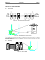
CH. 1
CHAPTER 1: INSTALLING THE OPTION CARD
1.1
Installation Hardware
Included in the packaging with the AF-300E$ option card should be the following:
1.2
A)
The option card (RTU or Genius),
B)
One HE300KIT399 (consisting of one 0.5 inch plastic standoff, one M3 x 5 screw and one
lock washer) for drives under 40 hp,
C)
One HE300KIT401 (consisting of one 0.63 inch metal standoff, one metal bracket, two
plastic fasteners, four M3 x 5 screws and four lock washers) for drives 40 hp and larger,
and
D)
This document.
The Installation Procedure for Drives Under 40 Horsepower
The AF-300E$ Communications Option Cards have been designed to integrate seamlessly with the AF300E$ drive. The option card is installed within the drive cover, so that the NEMA rating of the drive is
maintained after installation of the option card.
1.
Power down the drive.
2.
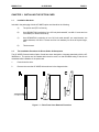
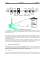
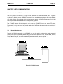
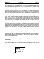
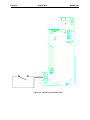
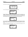
Remove the cover the AF-300E$ drive as shown in the diagram below.
Figure 1.1 – Drive Front Cover Removal Procedure
PAGE 10
CH. 1
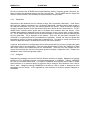
3.
09 AUG 2000
MAN0017-04
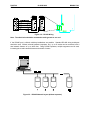
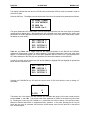
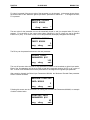
Install the supplied plastic 1/2" standoff (A') in hole (A).
Figure 1.2 – Drive Mounting Holes and Connectors (left), Mounting Hardware
(center, not to scale), and Option Card Location (right).
Drive shown is 1/2HP Af-300E$ viewed from the front.
MAN0017-04
09 AUG 2000
PAGE 11
CH. 1
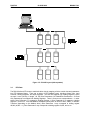
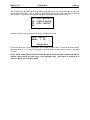
4.
Install the HE300 option board. Use the plastic guides (B) to properly align the bottom of the
option board. Snap the option board into the standoff (A') and option connector (C).
5.
Install the supplied M3 x 5 screw (D') with washer in hole D to secure the option board.
6.
Verify that jumper JP4 is removed and JP3 is on the two pins closest to the "E".
7.
After completing field wiring to the removable terminal strip(s), replace the front cover.
8.
Power up the drive as needed.
Figure 1.3 – Installing the Option Board (Side View of AF-300E$ 1/2HP shown)
PAGE 12
CH. 1
1.3
09 AUG 2000
MAN0017-04
The Installation Procedure for Drives 40 Horsepower and Larger
The AF-300E$ Communications Option Cards have been designed to integrate seamlessly with the AF300E$ drive. The option card is installed within the drive cover, so that the NEMA rating of the drive is
maintained after installation of the option card.
1.
Power down the drive.
2.
Remove the cover from the AF-300E$ using the 11 screws on the front panel.
3.
Remove the keypad and the keypad mounting plastic (4 screws) shown below.
Keypad
Option Card located under
keypad mounting plastic
Keypad Mounting Plastic
Figure 1.4 – Drive Keypad, Keypad Mounting Plastic and Option Card Location.
Drive shown is a 40HP AF-300E$ viewed from the front.
MAN0017-04
09 AUG 2000
PAGE 13
CH. 1
4.
Install corner brackets (A') on bottom corners of interface board (A).
5.
Install corner brackets (A') on metal bracket (B') using the supplied M3 x 5 screws and lock
washers in the corner bracket mounting holes (C).
6.
For the HE300GEN100 gently remove DC-to-DC converter (D), being careful not to bend the
pins. The HE300RSL100 does not have this part installed.
E
D
A
A
A’
E
B’
E
C
Figure 1.5 – Option Card Assembly front and side view (right)
PAGE 14
CH. 1
09 AUG 2000
MAN0017-04
7.
Install the assembled board into the drive using the M3 x 5 screws and lock washers in the
mounting holes (E). If you used the plastic standoff in the upper right hand corner of the board
you may need to use one of the M3 x 5 screws from the HE300KIT399.
8.
Verify that jumper JP4 is installed and JP3 is on the two pins closest to the "E".
9.
Replace the keypad mounting plastic and the keypad.
10.
After completing field wiring to the terminal strip(s), replace the front cover.
11.
Power up the drive as needed.
Note:
The metal standoff included with the HE300KIT401 can be used in place of the plastic standoff that
comes with the drive. The plastic standoff is the preferred method of installation, but if the metal standoff
is to be used the steps below should be followed.
1.
Once the keypad and keypad mounting plastic is removed, remove the plastic standoff in the
upper right corner of the drive board by holding the screw under the standoff with your finger,
while unscrewing the plastic standoff.
2.
Once the standoff is removed, screw on the metal standoff that is supplied with the
HE300KIT401.
3.
Do not remove the DC-to-DC converter as stated in step 6. Instead press the interface board
down onto the metal standoff until it snaps into place.
4.
To remove the board you may need to use a pair of fine tipped pliers to squeeze the tip of the
metal standoff together in order for the board to snap off of the standoff. To get to the tip of the
standoff you may need to remove the DC-to-DC converter as stated in step 6.
MAN0017-04
09 AUG 2000
PAGE 15
CH. 2
CHAPTER 2: GENIUS COMMUNICATIONS
2.1
Introduction to Genius
Genius is a high-speed token passing network which has been used in industrial applications for many
years. The network supports up to 32 devices, with baud rates of up to 153.6kbaud. A wide variety of
Genius devices exist which can reside on the network, ranging from intelligent I/O blocks to more
sophisticated communications devices such as personal computers. In recent years a number of third
party devices have emerged, including Operator Interface Units, valve manifolds, RF tag readers, etc.
In a typical industrial application, Genius devices are distributed throughout a fairly wide area, wired in a
daisy chained fashion with a single shielded, twisted pair. The AF-300E$ Genius option card allows the
AF-300E$ Drives to be distributed on the factory floor on the same twisted pair as the I/O blocks and
other Genius devices. This provides a new level of PLC integration for the drives. The physical nature of
the network can allow for great savings in wiring, as many discrete wires can be replaced with a single
communications cable. This allows tasks such as starting, stopping, reversing, and changing speeds to
be accomplished over the LAN. In addition, drive parameters and diagnostic data previously not available
to the PLC are easily accessible.
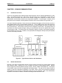
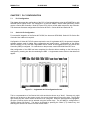
AF-300E$
Drive
Hand-held Monitor
Horner
Operator
Interface
Field Control
I/O Station
Communications Bus
Bus Controller
Series 90-70
Genius I/O Blocks
Figure 2.1 – Typical Genius Devices and Architecture
2.2
Network Architecture
Normally, a GE Fanuc programmable controller runs the network, through a PLC module called a Genius
Bus Controller (GBC). Devices (up to 32 in number) are wired in a daisy-chained fashion. Network
devices support four communications terminals, Serial 1, Serial 2, Shield In and Shield Out. The network
is terminated at each end with an appropriate terminating resistor. The value of the resistor should be
chosen to match the characteristic impedance of the cable. Refer to GE Fanuc Automation publication
GFK-90486 for help in selecting an appropriate cable type for your application. Note: If the characteristic
impedance of the cable is unknown, 120 ohm terminating resistors should be used.
PAGE 16
CH. 2
09 AUG 2000
Start
of Bus
MAN0017-04
End
of Bus
Terminating
Resistor
Terminating
Resistor
Serial 1
Serial 2
Shield In
Shield Out
Serial 1
Serial 2
Shield In
Shield Out
Figure 2.2 – Typical Genius wiring technique
Figure 2.3 – AF-300E$ Genius Connector Pinout
The AF-300E$ Genius connections are made on the rightmost of its two terminal strips (P2). In addition
to the normal Genius connections shown in Figure 2.2, Earth Ground must be connected to the “Shield
Out” terminal, Terminal 4.
Each of the (up to) 32 devices on the network is assigned a Genius Bus Address ranging from 0 to 31.
Bus Controllers are most typically assigned a Genius Bus Address of 31. In applications with redundant
bus controllers, the “backup” bus controller is address 30. Bus address 0 is normally reserved for the
Genius Hand Held Monitor.
Among other tasks, the bus controller allows Genius I/O (including the drives) on the network to be
mapped into PLC memory, monitoring inputs and controlling outputs. Intelligent, data intensive Genius
devices also share their data with the PLC through communications with the bus controller.
2.3
Genius Communications Services
As stated previously, the AF-300E$ Genius option card allows the drive to reside directly on the Genius
LAN, providing drive control and data access capabilities to the PLC. There are three types of
communications that can occur on the Genius LAN. These are I/O Services, Global Data and
Datagrams. The AF-300E$ supports all three of these communications types.
2.3.1
I/O Service
I/O Service is the manner in which data is transferred to and from Genius I/O Blocks. Outputs are
selectively written to each I/O block from the CPU bus controller each scan. The outputs written by the
MAN0017-04
09 AUG 2000
PAGE 17
CH. 2
CPU bus controller to the AF-300E$ drives include start/stop, fwd/rev, frequency (speed), fault reset, etc.
Many I/O blocks also broadcast inputs to the bus every bus scan. The AF-300E$ does not support this
means of communications, as it broadcasts its inputs (feedback) as global data.
2.3.2
Global Data
Global data is data broadcast over the network at large, with no particular “destination”. Each Genius
device has the capacity to broadcast up to 128 bytes of global data. Intelligent devices which reside on
the LAN (bus controllers, OIUs, etc.) can read this data off the network. These devices are intelligent
enough to interpret this data, as the data content differs from Genius device to Genius device. The AF300E$ Genius interface utilizes global data to broadcast drive feedback data over Genius. Drive
feedback data consists of parameters such as speed reference, torque, current, faults, function settings,
etc. The AF-300E$ Genius interface allows the system designer to select which data is broadcast by the
drive as global data. This is important for two reasons. First of all, the data which is desired to be
monitored on a regular basis varies from application to application. Second, the amount of global data
broadcast by the drive is directly proportional to response time. The ability to control the amount and
content of global data output is a vital feature of the AF-300 Genius interface.
In general, the procedure for configuring the drive’s Global output data is a process of mapping the global
output data words to drive parameters. There are three different means in which this “mapping” of global
data output words to drive parameters can be accomplished. These are; from the keypad, from the
Genius Hand Held Monitor, and from the optional personal computer configuration utility. Chapters are
dedicated to each of these configuration means.
2.3.3
Datagrams
Datagrams are messages sent over the Genius LAN from one device to another. Datagrams are typically
performed in PLC applications through a communications request, or COMREQ. Typically, COMREQs
are used for occasional data access. For instance, COMREQs would typically not be used to monitor
speed reference on a continuous basis, but might be used to change a drive parameter once a shift or
once a week. Datagrams (through COMREQs) could also be used to upload or download all drive
parameters over the network. In PLC applications, a bus controller is required to perform datagrams or
COMREQs.
PAGE 18
CH. 2
09 AUG 2000
NOTES
MAN0017-04
MAN0017-04
09 AUG 2000
PAGE 19
CH. 3
CHAPTER 3: RTU COMMUNICATIONS
3.1
Introduction to RTU Communications
The RTU protocol has become a de facto industry standard over the past several years. Originally
developed by Modicon as the MODBUSTM protocol, it has gained wide acceptance due to its simplicity
and versatility. It is a protocol which has translated well to various media, as it is used with RS-232, RS485, radio modems, fiber optics etc. It is the most common protocol of SCADA (Supervisory Control And
Data Acquisition) and DCS (Distributed Control Systems) Systems.
The AF-300E$ Remote Serial Link option card allows the AF-300E$ drive to act as an RTU slave.
Therefore it is able to communicate to the multitude of RTU masters (hosts) in use in industrial
applications. Through the option card, the AF-300E$ drive offers both RS-232 and RS-485 interfaces for
RTU communications.
3.2
Network Architecture
Through the RS-232 connection, the AF-300E$ can only be used in point-to-point mode, connected
directly to an RTU host less than 50 feet away. Five conductors should be used, Transmit Data, Receive
Data, Signal Ground, Request To Send, and Clear to Send. Other network topologies can be used
through the RS-232 port, but external hardware (converters/modems, etc.) is required.
Figure 3.1 – RS-232 Layout
PAGE 20
CH. 3
09 AUG 2000
MAN0017-04
Figure 3.2 – RS-232 Wiring
Note: The shield wire should be connected to earth ground on one end.
If the RS-485 port is utilized, multidrop installations are possible. Standard RS-485 wiring techniques
should be used. Without external hardware (repeaters, etc.), up to 32 nodes can be connected, with a
total network distance of up to 4000 feet. Using RS-485 repeaters, multiple segments can be used,
increasing the overall network distance and number of nodes.
Figure 3.3 – RS-485 Network Layout (without repeaters)
MAN0017-04
09 AUG 2000
PAGE 21
CH. 3
Figure 3.4 – RS-485 Wiring
Note: The shield wire should be connected to earth ground on one end.
The network is terminated at each end with an appropriate terminating resistor. The value of the resistor
should be chosen to match the characteristic impedance of the cable. Note: If the characteristic
impedance of the cable is unknown, 120 ohm terminating resistors should be used.
Note: Signal Ground must be run on the network if 7V or greater of ground potential exists
between any two devices
PAGE 22
CH. 3
09 AUG 2000
MAN0017-04
Figure 3.5 – RS-485 Layout (with repeaters)
3.3
RTU Data
The RSL100 allows RTU hosts to read/write drive data by mapping all drive control data and parameters
into RTU Address Space. There are a variety of RTU Address types, including Output Coils, Input
Contacts, Holding Registers, and Input Registers. The RSL100 supports only Holding Registers, which
are each 1 word (16 bits), in length. All 122 Drive Parameters (101 Read/Write Parameters + 21 Read
Only Parameters) are mapped into Holding Registers. There is a one-to-one correspondence -- in other
words, Drive Parameter 1 is mapped to Holding Register 1, Drive Parameter 2 is mapped to Holding
Register 2, and so on. Note that Modbus addresses usually have an offset of 4001, 40001, or 400001.
Therefore (depending on the Modbus driver) Drive Parameter 1 may correspond to holding register
40,002 (40,001 + 1), Drive Parameter 2 may correspond to holding register 40,003, and so on.
MAN0017-04
3.4
09 AUG 2000
PAGE 23
CH. 3
RTU Commands and Responses
RTU communications is made between an RTU Host and one or more RTU Slaves. Commands are
communications from the Host to a Slave, and Responses are communications from the Slave to Host.
Commands and Responses consist of "message frames" in either ASCII or RTU (binary) format, which
contains the following information:
1.
2.
3.
4.
Slave Address
Function Code
Data
Error Check Code
If an RTU command's slave address matches a slave's address, that slave executes the indicated
Function Code and then returns an RTU Response back to the Host. If an RTU command's slave
address is zero, all RTU slaves execute the indicated Function Code and do not return an RTU response.
Note that only Function Codes 6 and 16 may be "broadcast" in this way. If the RTU slave detects an
error, it does not execute the indicated Function Code, but may return an Exception Response instead.
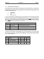
Table 3.1 lists the exception codes supported by the RSL100.
Table 3.1 – Exception Codes
Code
Name
Meaning
01
Illegal Function
Invalid command function was sent
02
Illegal Data Address
Invalid reference, or size exceeded table bounds
03
Illegal Data Value
Not valid data for a particular reference
04
Failure in Device
See loopback diagnostic test command for details
To access the holding register (drive parameter) data, the RSL100 supports 3 RTU function codes
(Function Codes 3, 6, and 16). The RSL100 also supports Function Code 8, the Loopback Diagnostic
Test. All four supported Function Codes are listed in Table 3.2. The Sub-function Codes for Function
Code 8 are listed in Table 3.3.
Table 3.2 – Supported Function Codes
Code
Meaning
I/O
Type
Min
Max
03
Read Holding Registers
I
Word
1
125
06
Preset Single Register
0
Word
1
1
08
Loopback Diagnostic Test
16
Preset Multiple Registers
(See Table 3.3)
0
Word
1
125
PAGE 24
CH. 3
09 AUG 2000
MAN0017-04
Table 3.3 – Sub-Function Codes for the Loopback Diagnostic Test
Code Meaning
I/O
00
Return 2-Byte query data
I
01
Re-start communications hardware (no response)
0
02
Return 16-bit diagnostics register
I
03
Change ASCII mode delimiter (LF is default)
0
04
Force Slave into listen only mode (no response)
0
10
Clear counters and diagnostic register
0
11
Return 16-bit bus message count
I
12
Return 16-bit bus CRC error count
I
13
Return 16-bit bus exception error count
I
14
Return 16-bit Slave message count
I
15
Return 16-bit Slave no response count
I
3.5
RTU Setup Parameters
A number of RTU Setup parameters must be set in the drive before the RSL100 can successfully
communicate with a RTU Host. Table 3.4 lists these parameters. These parameters may be set with the
AF-300E$ keypad, or the Horner Electric Drive Configuration Software (optional). Each of these devices
has a chapter dedicated to its operation.
Table 3.4 - RTU Setup Parameters
Parameter
Options
RTU Slave Address
0 to 128
Protocol
RTU (binary) or ASCII
Baud Rate
300 to 19,200 baud
Parity
None, Odd, or Even
Stop Bits
1 or 2
Port Type
RS-232 or RS-485
Handshaking
None, Software, Hardware, or Multidrop
DCS Timeout
0 (disabled) to 12 Seconds
MAN0017-04
09 AUG 2000
PAGE 25
CH. 4
CHAPTER 4: KEYPAD OPERATION
4.1
Initializing Drive and Option Card Function Codes (Parameters) through Keypad
With the option card installed, two sets of drive parameters (Function Codes) must be configured for
proper operation of the drive <and> communications with the drive over the Option card’s
communications channel. The first set are the drive specific parameters which define drive operation and
are described in the GE Drives (AF-300E$) Instructions. The second set are the option card specific
parameters which define the operation of the communications channel and are described below.
While other methods are available for modifying both Drive and Option Card parameters, it is typical that
the drive’s keypad will be used initially for setting both sets of drive parameters. Keypad operation
pertaining to modification of drive parameters is described in the GE Drives (AF-300E$) Instructions.
However, additional information is provided below pertaining to the additional option card parameters (not
covered by the GE Drives manual) and slight variations in keypad operation caused by the presence of
the Option Card. Note that option card parameters will only be visible through the keypad if the option
card is installed. Additionally, the option card parameters will start at the end of the Drive’s parameter list
and will be prefixed with ‘P’.
When the option card is installed, the keypad does not always have write access to both sets of drive
parameters. Write permission by the drive’s keypad is removed when control of the drive has been
granted to the communications channel. This feature prevents undesirable concurrent write access to a
parameter both by the communications channel and the drive’s keypad.
At power-up, default operation verifies the current Option Card parameters and valid, initializes and
grants drive control to the communications channel. Any attempt to change drive parameters with the
keypad from that point will be blocked with the display message of ‘Option Active’. To gain write access
to the drive’s keypad, the following steps must be followed:
1.
2.
3.
4.
Remove power from the drive. (See RS-232 Wiring on page 20.)
Jumper the RTS/CTS of the RS232 port (P1). (See RS-232 Wiring on page 20.)
Verify NO jumper at RX/TX of the RS232 port (P1).
Return power to the drive.
At this point, all drive control is local and initialization of the communications channel is stalled.
Additionally, write access is now granted to the drive’s keypad and the Drive and Option Card parameters
can be changed. Section 4.3 describes the method to enter option card parameters and their associated
description. Section 4.4 describes option card parameter verification and immediately releasing control to
the communication channel (completing initialization). However, before the next power-cycle, the
RTS/CTS jumper must be removed to allow normal operation.
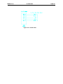
PAGE 26
CH. 4
4.2
09 AUG 2000
MAN0017-04
Keypad Layout
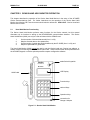
The keypad consists of eight buttons, three LEDs, a 4-digit display, and a LCD display. Figure 4.1
(below) shows the keypad:
Figure 4.1 – Keypad Layout
4.3
Setting the Drive Option Parameters
4.3.1
Non-volatile memory modification through keypad (HE300GEN100 ONLY)
The HE300GEN100 option card contains non-volatile memory, which is used to store ‘mapping’
information on which drive parameters to pass over the current Genius connection. More specifically, this
information defines the number and a listing of the drive parameters both for those received in the Genius
‘Directed’ data frame and those sent in the Genius ‘Global’ data frame. This information can be loaded to
non-volatile memory through one of four different sources: Factory defaults, Drive Keypad, Genius Handheld Programmer and DrvCfg (personal computer configuration software).
To use the drive’s keypad to modify non-volatile memory requires first gaining keypad write access (as
described in section 4.1) and then modifying option card ‘mapping’ parameters P04-P29. Then,
parameter P03 must be set to ‘Keypad’ (1) and control returned to the option card (as described in
section 4.4). Once the parameters are loaded, P03 will then be reset to ‘Option card’ (0), which indicates
MAN0017-04
09 AUG 2000
PAGE 27
CH. 4
that no change will be made to non-volatile memory on the next power-cycle. Note that P03 can also be
set to ‘Factory Presets’ (2) prior to releasing control to the option card, which will cause non-volatile
memory to be loaded with factory default values (see figure 7.4). Changes made to non-volatile memory
‘mapping’ information with the Genius Hand-held or the personal computer configuration software can be
made during run-time without dependency on P03.
When setting the ‘mapping’ parameters, P04 and P05 respectively select the amount of data output
(global) and data input (directed) from the drive to the Genius network. These sizes are configurable to
give the user flexibility in setting the ratio between number of parameters needing immediate access and
network loading. Since global and directed data are passed on the network on a continuous manner, only
those drive parameters that need immediate visibility should be entered into these ‘Pxx’ parameters.
Drive parameters that only need occasional access should be acquired through the datagram service.
Parameters P06 through P17 are used to specify the drive parameters that are output (global) to the
Genius network. Each ‘Pxx’ parameter specifies a corresponding drive parameter number (listed in
chapter 8) that will produce a word (16bit) value in the drive’s global data space. Parameters P18
through P29 are used to specify the drive parameters that are input (directed) from the Genius network.
Again, each received drive parameter will consume a word (16bit) value in the drive’s directed data
space. Note that drive parameter numbers that are specified as READ ONLY should not be used in
parameters P18 through P29.
The drive’s keypad can be used to display the current contents of non-volatile memory (actual
configuration) with P04 through P29 regardless of the method used to load non-volatile memory with the
following exceptions. First, changes made through the Genius Hand-held Programmer and the personal
computer configuration software are NOT correctly reflected until the next power cycle if the drive is in
Local control when change is made. Secondly, both the Genius Hand-held Programmer and personal
computer configuration software have the capability to configure larger Genius global and directed data
frames for the Genius network than the drive’s keypad. Those configured drive parameters beyond the
ability of the keypad display will NOT be viewable.
4.4
Transferring Drive Control from the Keypad to the Option Card
After setting the option parameters to the desired values, control of the drive can be transferred from the
keypad to the option card. This is accomplished from the keypad by setting the "Control" parameter (P02
on the GEN100 and P08 on the RSL100) to a value of "1". This "Control" parameter is set in the same
fashion as any other option parameter.
After the Control Option Parameter has been set to a value of 1, the option card will "check" the
parameters to make sure that the values are legal. If the values are legal, the option card will assume
control of the drive and Step 8 of the drive setup process can be made (see Section 4.5. on the
following page.)
Before attempting to set the drive option parameters from the keypad, make sure that Steps 1-5 of the
drive setup process have been followed. These are listed in Section 4.5 (Page 4-5), which follows later in
this chapter.
After powering up the drive, the drive's LCD display should display the following:
STOP
PRG > DATA SET
>> > LED SEL
PAGE 28
CH. 4
09 AUG 2000
MAN0017-04
This display indicates that the drive is in STOP mode, and that the PRG key must be pressed in order to
set the drive data.
Press the PRG key. The display now shows the start of the list of the normal drive parameters as follows:
00
01
02
03
FREQ COMND
OPR METHOD
MAX Hz
BASE Hz-1
The option parameters are at the bottom of the list, and cannot be seen until the cursor keys are pressed
multiple times to display them. After pressing the UP or DOWN cursor keys repeatedly, the option card
parameters are finally displayed as follows (note that holding the cursor keys down continuously causes
the display to scroll quickly:
P00
P01
PO2
PO3
OPTION
OPTION
OPTION
OPTION
0
1
2
3
Table 4.1 and Table 4.2 on Pages 29-30 list the option parameters for the RSL100 and GEN100,
respectively (Similar data is shown in earlier chapters). Each option parameter is set in the exact same
fashion. For illustrative purposes, we will set option parameter P00 to a value of 25. P00 represents the
RTU Slave Address for the RSL100, and represents the Genius Bus Address for the GEN100.
In order to set P00, use the cursor keys (UP and/or DOWN) to highlight P00 (the highlight is represented
below with the underlined text).
P00
P01
PO2
PO3
OPTION
OPTION
OPTION
OPTION
0
1
2
3
Pressing the FUNC/DATA key will show the current value of P00, and allow the user to change it if
necessary.
P00 OPTION 0
0
0~255
The bottom line of the display will flash between the allowable data range (in this case 0~255) and the
prompt STORE > F/D KEY. The current value of the parameter is shown on the third line (in this case
0). Pressing the cursor keys (UP, DOWN or >>) causes the new value to change. See the Drive User's
Manual for detailed instructions on keypad data entry operation. In this case, pressing the UP key will
cause the new value to increment, and move the current stored value from the third line to the second
line, as shown below:
MAN0017-04
09 AUG 2000
PAGE 29
CH. 4
P00 OPTION 0
0
25
0~255
When the option parameter is at the desired value (in this case 25), pressing the FUNC/DATA key will
cause the parameter to be stored. As the data is being stored, the bottom line of the display will show a
DATA STORING message. After the data has been stored, the option parameter list will return to the
display and the next option parameter will be highlighted, as shown below:
P01
P02
PO3
PO4
OPTION
OPTION
OPTION
OPTION
1
2
3
4
Because option parameter P00 was just edited, option parameter P01 is now highlighted.
It is important to note that the keypad will allow a larger data value to be input
than is legal for a given parameter. In the case of P00, the legal data values are 031 for the GEN100, or 1-128 for the RSL100. The keypad will allow any data value
to be entered which is 0-255. Option parameters with Illegal data values will be
flagged by the option card when drive control is transferred from the keypad to
the option card.
NOTE: When defining P06-P29, bit mapped values should be placed first in the parameter map.
See Pages 43 through 46 to determine which values are bit mapped.
P00
P01
P02
P03
P04
P05
P06
P07
P08
Table 4.1 – Option Parameters for RTU Option Card (RSL 100)
Parameter
Legal Values
RTU Address
0 to 128
Protocol
0 = RTU (binary) or 1 = ASCII
Baud Rate
0 = 300, 1 = 600, 2 = 1200, 3 = 2400, 4 = 4800, 5 = 9600, 6 = 19200
Parity
0 = No, 1 = Odd, 2 = Even
Stop Bits
0 = 1 Stop Bit, 1 = 2 Stop Bits
Port Type
0 = RS-232, 1 = RS-485
Handshaking
0 = None, 1 = Software, 2 = Hardware, 3 = Multidrop
DCS Timeout
0 (disabled) to 12 Seconds
Control
1 = Option Card Control
PAGE 30
CH. 4
09 AUG 2000
MAN0017-04
Table 4.2 – Option Parameters for Genius Option Card (GEN100)
Parameter
Legal Values
P00
Bus Address
0 to 31
P01
Baud Rate
0 = 153.6k EXT, 1 = 153.6k STD, 2 = 76.8k, 3 = 38.4k
P02
Control
1 = Option Card
P03
Cfg. Values
0 = Option Card, 1 = Keypad, 2 = Factory Presets
P04
Global Data Length
1 to 12
P05
Directed Data Length
1 to 12
P06 - P17
Broadcast Data 1 – 12
101 to 121 or 255
P18 - P29
Control Data 1 - 12
0 to 100, 122 or 255
4.4
Transferring Drive Control from the Keypad to the Option Card
After setting the option parameters to the desired values, control of the drive can be transferred from the
keypad to the option card. This is accomplished from the keypad by setting the "Control" parameter (P02
on the GEN100 and P08 on the RSL100) to a value of "1". This "Control" parameter is set in the same
fashion as any other option parameter.
After the Control Option Parameter has been set to a value of 1, the option card will "check" the
parameters to make sure that the values are legal. If the values are legal, the option card will assume
control of the drive and Step 8 of the drive setup process can be made (see Section 4.5 on the following
page).
If one or more of the drive option parameters are illegal, an "Error 5" message will be displayed (see
below)
OPTION ERROR
F/D > FACTOR
>> > ITEM SEL
RESET
The option parameter with the illegal value can be determined by examining the value of the Control
Parameter (P02 for the GEN100 and P08 for the RSL100). The value of the Control Parameter will be
100 + the option parameter in error. If P00 is illegal, for instance, the Control Parameter will have a value
of 100. If P05 is illegal, the Control Parameter will have a value of 105.
After correcting the illegal parameter, the Control Parameter must be once again set to a value of 1. The
option card will then recheck the option parameter values. If all the parameters are now legal, control will
be transferred and the Error 5 can now be reset. This is accomplished by going to the main display (by
pressing the PRG key), and then pressing the RESET key. After the drive has successfully cleared the
error, Step 8 of the drive setup process can be made (see Section 4.5 on the following page).
MAN0017-04
4.5
09 AUG 2000
PAGE 31
CH. 4
Drive Setup from the Keypad
The following steps need to be taken in order to place the drive (with option card) into service:
1.
Install the communications option card as described in Chapter 1.
2.
Make sure that the jumper has been removed which connects the FWD and CM terminals on the
Drive terminal strip. This jumper is factory installed and must be removed prior to operation of the
drive with the option card.
3.
Wire the communications option card to the appropriate Genius (GEN100) or RTU (RSL100)
network. Wiring diagrams and pinouts are provided in Chapter 2 (GEN100) and Chapter 3
(RSL100) respectively.
4.
Terminals 3 and 4 on P1 of the option card must be jumpered together. This can be
accomplished with a short piece of copper wire, alligator clip jumper wire, a permanently mounted
switch, etc. (See Figure 4-2 on the following page). If a permanently mounted switch performs
this function, place the switch in the CLOSED position.
5.
Power up the drive. Prior to powering up the drive, make sure that all instructions and
provisions described in the AF-300E$ User's Manual have been followed.
6.
Set the drive option parameters (P00>P08 for the RSL100, P00>P29 for the GEN100) to the
desired values (see Section 4.3). IMPORTANT: IN ORDER FOR CHANGES IN P04-P29 MADE
FROM THE KEYPAD TO TAKE EFFECT, P03 MUST BE SET TO A 1 (GEN100 ONLY).
7.
Turn over control of the drive from the keypad to the option card. (See Section 4.4).
8.
Remove the jumper from option card terminals 3 and 4 on P1. If a permanently mounted switch
performs this function, place the switch in the OPEN position (See Figure 4-2 on the following
page).
9.
This completes the option card setup process using the AF-300E$ drive keypad.
PAGE 32
CH. 4
09 AUG 2000
Figure 4.2 – Switch for Terminals 3 and 4
MAN0017-04
MAN0017-04
09 AUG 2000
PAGE 33
CH. 5
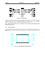
CHAPTER 5: GENIUS HAND HELD MONITOR OPERATION
This chapter describes the operation of the Genius Hand Held Monitor in the setup of the AF-300E$
Genius Communications Card. For further instructions on the operation of the Genius Hand Held
Monitor, the following GE Fanuc document should also be referenced: GFK-0121E - Genius Hand-held
Monitor User's Guide
5.1
Hand Held Monitor Functionality
The Genius Hand Held Monitor performs many functions for the Genius network, but this manual
discusses only its functions in setting up the HE300GEN100 communications interface. The Genius
Hand Held Monitor (HHM) can only be used as follows with the GEN100 card:
1.
2.
3.
4.
Set the number of directed data words (from 1 to 30),
Map the directed data to drive parameters,
Set the number of global data words broadcast by the AF-300E$ (from 1 to 30), and
Map drive parameters to global data.
The Hand Held Monitor (HHM) cannot be used to set the Genius baud rate, Genius bus address, or
transfer control from the keypad to the GEN100 option card. These functions must still be performed from
the AF-300E$ keypad, or with the optional personal computer configuration software.
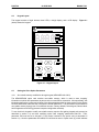
Mode Select Keyswitch
Genius
MON
Hand Held Monitor
CFG
GE Fanuc
LCD Display
HHM Cable
F1
F2
F3
F4
7
8
9
Home
4
5
6
Menu
1
2
3
Clear
_+
0
On
Off
Function Keys
Decimal Keys
Operation Keys
Connection for
Charger / Adapter
Figure 5.1 – Genius Hand Held Monitor
PAGE 34
CH. 5
5.2
09 AUG 2000
MAN0017-04
Changing GEN100 Setup Parameters
After powering up the Hand Held Monitor and setting its bus baud rate to match the bus, the main menu
(below) is displayed:
F1:
F2:
F3:
F4:
HHM UTILITIES
ANALYZE
CONFIGURATION
DEVICE MEMORY
Select F2 (Analyze), and the following menu is displayed:
F1:
F2:
F3:
F4:
MONITOR BLOCK
MNTR/CNTL REF
BLOCK/BUS STS
PULSE TEST
Selecting F3 (Block/Bus Status) causes a screen similar to the following to appear:
GENI
BUS ADR: 31
V1.7
REG 32766
nxt prv r/g bus
Pressing F1 (nxt) or F2 (prv) toggles through the Genius devices on the bus. Continue toggling through
the devices until the AF-300E$ drive to be configured is selected. A screen similar to the following will
appear:
GENIO
BLOCK 1
NO FORCE
nxt prv
V2.0
actv
bus
Select F3 (actv) to make this block active. The word "ACTIVE" will appear on the display to indicate the
active status of this block. Now that the block is active, return to the main menu by pressing the HOME
key.
F1:
F2:
F3:
F4:
HHM UTILITIES
ANALYZE
CONFIGURATION
DEVICE MEMORY
MAN0017-04
09 AUG 2000
PAGE 35
CH. 5
This time, select F3 (configuration) from the main menu, and the following menu appears:
F1: PROG BLOCK ID
F2: CONFIG BLOCK
F3: COPY CONFIG
F4:
Select F2 (config block), and the GEN100's first configuration screen appears:
MAXIMUM GLOBAL
INPUT WORDS
rng
chng
7
nxt
"MAXIMUM GLOBAL INPUT WORDS" is the parameter to be set, and "7" is the current value of this
parameter. All GEN100 configuration screens are formatted in this fashion, with a description of the
parameter in the top two lines, the current value displayed on the third line, and the available function
keys displayed on the fourth line. Pressing F1 (rng) causes the HHM to display the legal range of data
entry for the parameter. After pressing F1 (rng), the above display changes to the following:
MAXIMUM GLOBAL
INPUT WORDS
MIN:
0
MAX:
16384
Keep in mind that the minimums and maximums displayed refer to the range of data which the HHM will
allow to be entered. This range may or may not match the legal range for the parameter. Above, the
data entry range for the maximum global input words is 0-16384, while the legal range for that parameter
is 0-30.
Pressing the F1 key again causes the display to return to its previous state, displaying the current
parameter value and the function key selections.
MAXIMUM GLOBAL
INPUT WORDS
rng
chng
7
nxt
PAGE 36
CH. 5
09 AUG 2000
MAN0017-04
F2 (chng) is pressed if the current value of the parameter is to be changed. In the screen shown above,
the current value of the "Maximum global input words" parameter is shown as 7. To change that value,
F2 is pressed:
MAXIMUM GLOBAL
INPUT WORDS
_
chng
entr
The new value for the parameter can now be numerically keyed in, and it is accepted when F3 (entr) is
pressed. To revert back to the current value (abort changing it), the F2 (chng) key can be pressed
instead of F3 (entr). If we enter a value of 3 for this parameter, the display changes to the following:
MAXIMUM GLOBAL
INPUT WORDS
rng
chng
3
nxt
The F4 key can be pressed to advance to the next parameter.
GLOBAL INPUT
PARAMETER #00
105
rng chng
nxt
The next 30 screens allow the user to map parameter numbers to be broadcast as global input words.
Each of the 30 parameters will be set to either a legal drive parameter number (0-122), or to a value of
255. A value of 255 indicates that no drive parameter is to be mapped to this global input parameter.
After cursoring through the Global Input Parameters #00-#29, the Maximum Directed Data parameter
screen is shown as follows:
MAXIMUM DIRECTED
DATA WORDS
2
rng chng
nxt
Following this screen are the 30 screens for setting the Directed Data Parameters #00-#29, an example
of which is shown below:
DIRECTED DATA
PARAMETER #00
rng
chng
95
nxt
MAN0017-04
09 AUG 2000
PAGE 37
CH. 5
After configuring an AF-300E$ drive in the fashion described above, the configuration data for one drive
can be copied to another. This is useful for applications with multiple drives with identical GEN100
configuration. To select this option, display the Block Configuration Menu (shown below):
F1: PROG BLOCK ID
F2: CONFIG BLOCK
F3: COPY CONFIG
F4:
Selecting F3 (Copy Config) displays the following configuration screen:
COPY CONFIG
FROM: 1 TO:
_
chng entr
This screen allows the current configuration to be copied to another block. In the screen shown above,
the current block is "1". To copy this configuration to block number 4 simply enter a numeric 4 and press
F3 (entr).
NOTE: When defining Global Input Parameter #00-#29 and Directed Data Parameter #00-#29, bit
mapped values should be placed first in the parameter map. See Pages 43 through 46 to
determine which values are bit mapped.
PAGE 38
CH. 5
09 AUG 2000
NOTES
MAN0017-04
MAN0017-04
09 AUG 2000
PAGE 39
CH. 7
CHAPTER 7: PLC CONFIGURATION
7.1
PLC Configuration
This chapter discusses the configuration of the PLC in Genius applications using the AF-300E$ drive with
GEN100 Genius option board. As mentioned in a previous chapter, Genius LANs performing control
require a Genius Bus Controller. Most GE Fanuc PLCs offer a module which acts as the bus controller.
This document discusses configuration of the Series 90 PLCs -- Series 90-30 and Series 90-70.
7.2
Series 90-70 Configuration
For successful integration of the Series 90-70 GBC, the document GFK-0398, Series 90-70 Genius Bus
Controller User's Manual is required.
Configuration of Series 90-70 PLC system requires the use of Logicmaster 90-70, the personal computer
software package used for ladder logic programming and system setup. Configuration of the Genius
devices residing on the LAN with Logicmaster 90-70 cannot be accomplished until the Genius Bus
Controller (GBC) is configured. For instructions on that process, consult GFK-0398 from GE Fanuc.
After configuration of the GBC has been completed, the Genius devices residing on the LAN may be
configured by zooming into the slot containing the GBC. A Logicmaster screen similar to that below will
appear:
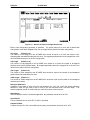
Figure 7.1 – Logicmaster 90-70 Configuration Screen
This is a representation of the Genius LAN, with each device shown as a "block". Because only eight
devices can be shown on the screen at once, the screen "wraps around" from left to right. The left and
right cursor keys are used to select the device to be configured. When the desired block is highlighted,
the type of Genius device can be selected using the function keys. The AF-300E$ is configured as a
"Generic Genius I/O Device". This device is selected by pressing the "Other" (F7) function key, and
selecting the "Generic I/O" device from the devices listed.
PAGE 40
CH. 7
09 AUG 2000
MAN0017-04
Figure 7.2 – Generic I/O Device Configuration Screen
Below, each configuration parameter is described. The proper setting for a drive with a default data
configuration is also listed. Figure 7-4 on the next page lists the default drive data configuration.
%I Length
(Default = 16)
The number of %Is assigned to the AF-300E$ drive should be equal to 16 times the number of bitmapped global data words broadcast by the drive. Bit mapped parameters should be mapped first in the
drive and defined using %Is in the PLC configuration.
%Q Length
(Default = 16)
The number of %Qs assigned to the AF-300E$ drive should be 16 times the number of bit-mapped
directed control words (directed data). Bit mapped parameters should be mapped first in the drive and
defined using %Qs in the PLC configuration.
%AI Length
(Default = 6)
The number of %AIs assigned to the AF-300E$ drive should be equal to the number of non-bitmapped
global data words broadcast by the drive.
%AQ Length (Default = 1)
The number of %AQs assigned to the AF-300E$ drive should be equal to the number of non-bitmapped
directed control words.
Reference Addresses
In addition to the length of each of the four I/O references (%I, %Q, %AI, %AQ), the starting reference
address for each I/O type must be set for each of the I/O references with a non-zero length. This
reference address should not conflict with any other I/O module or Genius device.
Redundancy
If the AF-300E$ is used in a redundant application, this parameter should be set to YES.
Input Default
The input defaults can be set to OFF or HOLD, as desired.
Outputs Enabled
If outputs from the PLC are to be enabled (most cases), this parameter should be set to YES.
MAN0017-04
09 AUG 2000
PAGE 41
CH. 7
%I, %AI, %G, %R
P08
Table 7.1 – Default Drive Configuration Parameters
Param.
Bit
90-70
Description
Description
/ Value
Map?
Data
Operation
Global Data Word 1
105
Yes
%I
Status
Output
Global Data Word 2
101
No
%AI
Frequency
Global Data Word 3
102
Output Current
No
%AI
P09
Global Data Word 4
103
Output Voltage
No
%AI
%I, %AI, %G, %R
P10
Global Data Word 5
104
No
%AI
%I, %AI, %G, %R
P11
Global Data Word 6
106
No
%AI
%I, %AI, %G, %R
P12
Global Data Word 7
107
Output Torque
Trip History
(low word)
Trip History
(high word)
No
%AI
%I, %AI, %G, %R
Not Used
N/A
---
---
Yes
%Q
%Q, %AQ, %G, %R
No
%AQ
%Q, %AQ, %G, %R
N/A
---
---
Keypad
Param.
P06
P07
P13-17
P18
P19
P20-29
Global Data Words
8-12
Directed Control
Word 1
Directed Control
Word 2
Directed Control
Words 3 - 12
255
96
95
255
Terminal I/O
(low word)
High Res. Freq.
Setting
Not Used
90-30 Data
%I, %AI, %G, %R
%I, %AI, %G, %R
Note: The reference types available for mapping into Series 90-30 memory are more numerous
than those available for the Series 90-70. This is due to the fact that the Series 90-70 performs
more data type checking than the Series 90-30. This extra checking requires that the number and
type of memory references match exactly in the Series 90-70. The Series 90-30 requires only that
the amount of data match exactly.
7.3
Series 90-30 Configuration
For full information on the configuration of Genius LANs with the Series 90-30 PLC, consult the GE Fanuc
document GFK-1034, Series 90-30 Genius Bus Controller User's Manual.
The Series 90-30 PLC is configured using Logicmaster 90-30. In the configuration package, the Genius
Bus Controller (GBC) configuration screen appears as follows:
Figure 7.3 – Series 90-30 GBC Configuration Screen
PAGE 42
CH. 7
09 AUG 2000
MAN0017-04
The devices residing on the Genius LAN are configured in the lower "Device Data" section of the screen.
The cursor keys are used to navigate around the screen. When the cursor is on the "Device Data"
section of the screen, the PageUp and PageDown keys are used to select the Device number. Once the
proper device number is displayed for the AF-300E$, the following parameters can be set.
Device Type
The AF-300E$ is configured as a GENERIC device type, which is the default.
Input References (Input 1 Ref, Input 2 Ref)
These parameters specify where the AF-300E$'s global data is mapped in Series 90-30 memory. Legal
reference types for these parameters are %I, %G, %AI, and %R. As you can see, the global data
broadcast by the AF-300E$ can be divided into two different areas of PLC memory. For instance, part of
the global data could be mapped into %I, and the remainder into %AI. Two non-consecutive areas of the
same reference type could also be mapped. For instance, part of the global data could be mapped to
%R1, and the remainder to %R500.
Input Length (Input 1 Len, Input 2 Len)
These parameters specify how much global data is broadcast by the AF-300E$. If the Input Reference
specified is bit-type (%I, %G), the length parameter is in bits. If the Input Reference specified is word type
(%AI, %R), the length parameter is in words. The total amount of data mapped into the Series 90-30
must exactly match the total amount of global data broadcast by the AF-300E$.
If bit-type parameters are used then they must be defined in the first global words of the drive. They must
also be configured as bit-type data in the bus controller. For example: If the drive is configured to have
parameters 101 through 105 as global broadcast data then 105 must be placed first and then 101 through
104 can be in any order after them. The Genius Bus Controller would then be configured with 16 %Is and
4 %AIs, in that order.
Output References (Output 1 Ref, Output 2 Ref)
These parameters specify where the AF-300E$'s directed control data is mapped in Series 90-30
memory. Legal reference types for these parameters are %Q, %G, %AQ, and %R. As you can see, the
directed data input by the AF-300E$ can be divided into two different areas of PLC memory. For
instance, part of the global data could be mapped into %Q, and the remainder into %AQ. Two nonconsecutive areas of the same reference type could also be mapped. For instance, part of the directed
data could be mapped to %R1, and the remainder to %R500.
Output Length (Output 1 Len, Output 2 Len)
These parameters specify how much directed data is received by the AF-300E$. If the Output Reference
specified is bit-type (%Q, %G), the length parameter is in bits. If the Output Reference specified is word
type (%AQ, %R), the length parameter is in words. The total amount of data mapped from the Series 9030 must exactly match the total amount of global data received by the AF-300E$.
If bit-type parameters are used then they must be defined in the first global words of the drive. They must
also be configured as bit-type data in the bus controller. For example: If the drive is configured to have
parameters 95 through 97 as directed control data then 96 and 97 must be placed first and then 95 can
be after them. The Genius Bus Controller would then be configured with 32 %Qs and 1 %AQs, in that
order.
MAN0017-04
09 AUG 2000
PAGE 43
CH. 8
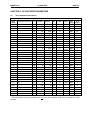
CHAPTER 8: AF300E$ DRIVE PARAMETERS
8.1
Drive Parameter Descriptions
Table 8.1 – Drive Parameter Descriptions
PARAM
NUMBER
0
1
2
3
4
5
6
7
8
9
10
11
12
13
14
15
16
17
18
19
20
21
22
23
24
25
26
PARAMETER DESCRIPTION
FC*
Frequency Command
00
01
02
03
04
05
06
07
08
09
10
11
12
13
14
15
16
17
18
19
20
21
22
23
24
25
26
Operation Method
Maximum Frequency
Base Frequency 1
Rated Voltage 1
Acceleration Time 1
Deceleration Time 1
Torque Boost 1
Elec. Thermal OL (Select)
Elec. Thermal OL (Level)
Restart after Power Failure
Frequency Limiter (High)
Frequency Limiter (Low)
Bias Frequency
Gain (Freq. Setting Signal)
Torque Limiter (Driving)
Torque Limiter (Braking)
DC Brake (Starting Freq.)
DC Brake (Brake Level)
DC Brake (Braking Time)
Multistep Freq. Setting 1
Multistep Freq. Setting 2
Multistep Freq. Setting 3
Multistep Freq. Setting 4
Multistep Freq. Setting 5
Multistep Freq. Setting 6
MINIMUM
MAXIMUM
N
N
N
N
N
Y
Y
Y
Y
Y
N
Y
Y
Y
Y
Y
Y
Y
Y
Y
Y
Y
Y
Y
Y
Y
Y
Hz
Hz
V
s
s
A
Hz
Hz
Hz
%
%
%
Hz
%
s
Hz
Hz
Hz
Hz
Hz
Hz
Hz
0
0
0
0
0
5
5
1
0
6
0
0
0
0
1
0
0
1
0
1
2
2
2
2
2
2
2
1 WORD
Ratedx20
Ratedx135
0
0
0
0
0
20
0, 20
0
0
0
0
0
0
0
0
0
0
4
400
400
400
200
180,255
180,255
60
100
30
400
400
400
400
400
400
400
27
0
2
-
0
1 WORD
R/W
Y
Hz
1
1 WORD
R/W
Y
-
0
0
0
11
1 WORD
R/W
R/W
R/W
R/W
N
N
Y
N
28
Slip Compensation Control
28
-9.9
5
29
30
31
32
Torque Vector Control
29
30
31
32
0
2
0
0
1
14
1
0x2222
X1 – X5 Terminal Function
1 WORD
R/W
R/W
R/W
R/W
R/W
R/W
R/W
R/W
R/W
R/W
R/W
R/W
R/W
R/W
R/W
R/W
R/W
R/W
R/W
R/W
R/W
R/W
R/W
R/W
R/W
R/W
R/W
LENGTH
2
1
400
400
480
3600
3600
20
2
27
Function Block (32-41)
CHANGE
WHILE
RUNNING
FORMAT
0
0
50
50
0, 80
0.01
0.01
0
0
Multistep Freq. Setting 7
Elec. Thermal OL (DB
Res.)
Number of Motor Poles
READ /
WRITE
UNIT
1 WORD
1 WORD
1 WORD
1 WORD
1 WORD
1 WORD
1 WORD
1 WORD
1 WORD
1 WORD
1 WORD
1 WORD
1 WORD
1 WORD
1 WORD
1 WORD
1 WORD
1 WORD
1 WORD
1 WORD
1 WORD
1 WORD
1 WORD
1 WORD
1 WORD
1 WORD
1 WORD
1 WORD
* The performance of these parameters has not been fully evaluated at the time of publication of this
manual.
PAGE 44
CH. 8
PARAM
NUMBER
33
34
35
36
37
38
39
40
41
42
43
44
45
46
47
48
49
50
51
52
53
09 AUG 2000
READ /
WRITE
CHANGE
WHILE
RUNNING
1 Word
R/W
R/W
R/W
R/W
R/W
R/W
R/W
R/W
R/W
R/W
Y
Y
Y
Y
Y
Y
N
N
Y
Y
0
1 Word
R/W
Y
-
0
1 Word
R/W
Y
103
-
0
1 Word
R/W
Y
0
3
-
0
1 Word
R/W
Y
0
0xFFFF
-
12
R/W
N
R/W
N
PARAMETER DESCRIPTION
FC*
Acceleration Time 2
33
34
35
36
37
38
39
40
41
42
0.01
0.01
0.01
0.01
0.01
0.01
50
0, 80
0.1
0
43
Deceleration Time 2
Acceleration Time 3
Deceleration Time 3
Acceleration Time 4
Deceleration Time 4
Base Frequency 2
Rated Voltage 2
Torque Boost 2
Function Block (43-51)
FMP Terminal (Pulse Rate
Mult.)
FMP Terminal (Voltage
Adjust)
FMP Terminal (Voltage
Adjust)
FMP Terminal (Function)
Y2 – Y5 Terminal Function
(low word)
Y1 Terminal Function (high
word)
FAR Function Signal
(Hysteresis)
FDT Function (Level)
FDT Function (Hysteresis)
OL Function signal (Level)
MAN0017-04
MINIMUM
MAXIMUM
UNIT
FORMAT
LENGTH
3600
3600
3600
3600
3600
3600
400
480
20
1
s
s
s
s
s
s
Hz
V
-
5
5
5
5
5
5
0
0
1
0
1 Word
6
100
-
44
50
120
45
65
46
47
1 Word
1 Word
1 Word
1 Word
1 Word
1 Word
1 Word
1 Word
2 Word
0
0xF
-
13
48
0
10
Hz
1
1 Word
R/W
Y
49
50
51
52
0
0
400
30
Ratedx135
0
1
0
1
6
0
1 Word
Ratedx20
Hz
Hz
A
-
1 Word
R/W
R/W
R/W
R/W
Y
Y
Y
Y
53
0
400
Hz
0
1 Word
R/W
N
54
0
400
Hz
0
1 Word
R/W
N
55
0
400
Hz
0
1 Word
R/W
N
56
0
30
Hz
0
1 Word
R/W
N
57
0.2
60
Hz
1
1 Word
R/W
N
58
0
10
S
1
1 Word
R/W
N
59
0.01
5
S
2
1 Word
R/W
Y
1 Word
1 Word
60
Function Block (53-59)
Jump Frequency (Jump
Freq. 1)
Jump Frequency (Jump
Freq. 2)
Jump Frequency (Jump
Freq. 3)
Jump Frequency
(Hysteresis)
Starting Frequency (Freq.)
Starting Frequency
(Holding Time)
Freq. Setting Signal Filter
61
Function Block (61-79)
60
0
1
-
0
1 Word
R/W
Y
62
61
0
8
-
0
1 Word
R/W
Y
62
0
1
-
0
1 Word
R/W
Y
64
LED Monitor (Function)
LED Monitor (Display at
Stop Mode)
Coeff. For Machine & Line
Speed
63
0.01
200
-
2
1 Word
R/W
Y
65
LCD Monitor
64
0
4
-
0
1 Word
R/W
Y
54
55
56
57
58
59
63
* The performance of these parameters has not been fully evaluated at the time of publication of this
manual.
MAN0017-04
PARAM
NUMBER
66
67
68
69
70
71
72
73
74
75
76
77
78
79
80
81
82
83
84
85
86
87
88
89
90
91
92
93
PARAMETER DESCRIPTION
Pattern Operation (Mode
Select)
Pattern Operation (Stage 1)
Pattern Operation (Stage 2)
Pattern Operation (Stage 3)
Pattern Operation (Stage 4)
Pattern Operation (Stage 5)
Pattern Operation (Stage 6)
Pattern Operation (Stage 7)
Acc./Dec. Pattern (Mode
Select)
Energy Saving Operation
Rev. Phase Sequence Lock
Data Initializing (Data
Reset)
Language
(Japanese/English)
LCD Display Brightness
Function Block (81-94)
Motor Sound (Carrier
Frequency)
Auto Restart (Restart Time)
Auto Restart (Freq. Fall
Rate)
Auto Reset (Times)
Auto Reset (Reset Interval)
Motor 1 (Capacity)
Motor 1 (Rated Current)
Motor 1 (No-Load Current)
Motor 2 (Rated Current)
Motor 1 Impedance (Tuning)
Motor 1 Impedance (%R1
Setting)
Motor 1 Impedance (%X1
Setting)
95
Data Protection
Additional V1 Analog
Voltage
High Res. Frequency
Setting (Pulses)
96
Terminal Input/Output (low
word)
97
Terminal Input/Output (high
word)
98*
Output Frequency
Compensation Input
94*
09 AUG 2000
PAGE 45
CH. 8
UNIT
FORMAT
LENGTH
READ /
WRITE
CHANGE
WHILE
RUNNING
-
0
1 WORD
R/W
N
s/s/s/s/s/s/s/-
7
7
7
7
7
7
7
1 WORD
1 WORD
R/W
R/W
R/W
R/W
R/W
R/W
R/W
Y
Y
Y
Y
Y
Y
Y
2
-
0
1 WORD
R/W
N
0
0
1
1
-
0
0
1 WORD
1 WORD
R/W
R/W
N
N
77
0
1
-
0
1 WORD
R/W
N
78
0
3
-
0
1 WORD
R/W
Y
79
80
0
0
10
1
-
0
0
1 WORD
1 WORD
R/W
R/W
Y
Y
81
0
10
-
0
1 WORD
R/W
Y
82
0
5
s
1
1 WORD
R/W
N
83
0
100
Hz/s
2
1 WORD
R/W
N
84
85
86
87
88
89
90
0
2
0
0
0
0
0
7
20
3
2000
2000
2000
1
s
A
A
A
-
0
0
0
6
6
6
0
1 WORD
1 WORD
R/W
R/W
R/W
R/W
R/W
R/W
R/W
Y
Y
N
N
N
N
N
91
0
50
%
2
1 WORD
R/W
Y
92
0
50
%
2
1 WORD
R/W
Y
95
0
1
-
0
1 WORD
R/W
N
-10
10
V
0
1 WORD
R/W
Y
-6000
6000
Pulses
14
1 WORD
R/W
Y
BIT
MAP
BIT
MAP
BIT
MAP
BIT
MAP
-
4
16 bits
R/W
Y
-
4
16 bits
R/W
Y
-6000
6000
Pulses
14
1 WORD
R/W
Y
FC*
MINIMUM
MAXIMUM
65
0
3
66
67
68
69
70
71
72
0
0
0
0
0
0
0
6000
6000
6000
6000
6000
6000
6000
73
0
75
76
1 WORD
1 WORD
1 WORD
1 WORD
1 WORD
1 WORD
1 WORD
1 WORD
1 WORD
1 WORD
* The performance of these parameters has not been fully evaluated at the time of publication of this
manual.
PAGE 46
CH. 8
PARAM
NUMBER
09 AUG 2000
PARAMETER DESCRIPTION
99
100
101
102
103
104
Drive Torque Limit Setting
105
Operation Status
106
107
108
109
110
111
112
Trip History (low word)
113
114
115
116
117**
118
119
Braking Torque Limit Setting
Output Frequency
FC*
MINIMUM
20
0,20
-6000
MAN0017-04
Fin Temperature
Internal Temperature
BIT
MAP
V2 Terminal Voltage
V1 Terminal Voltage
C1 Terminal Current
FMP Frequency
FMA Output Voltage
Option Status
** Not Operational at this time.
h
A
C
C
3
3
15
0
16
0
0
1 WORD
1 WORD
R
R
R
R
R
R
R
Y
Y
Y
Y
Y
Y
Y
-
9
16 bits
R
Y
V
V
mA
1 WORD
V
V
1
1
1
0
1
1
1 WORD
R
R
R
R
R
R
Y
Y
Y
Y
Y
Y
-
4
16 bits
R
Y
-
4
16 bits
R
Y
-
17
16 bits
R/W
Y
Pulses
Pulses
FMP Output Voltage
122
Y
-
BIT
MAP
Inverter Rated Current
Inverter Terminal Input (high
word)
R
1 WORD
%
%
%
0
0
14
10
10
10
Total Operation Time
121
16 bits
%
%
Inverter Capacity
120
8
180,255
180,255
6000
Trip History (high word)
Inverter Terminal Input (low
word)
Y
Y
Y
Y
Y
Y
LENGTH
Output Torque
Output Terminal Condition
1 WORD
R/W
R/W
R
R
R
R
FORMAT
Output Voltage
BIT
MAP
CHANGE
WHILE
RUNNING
UNIT
Output Current
BIT
MAP
READ /
WRITE
MAXIMUM
BIT
MAP
BIT
MAP
BIT
MAP
BIT
MAP
BIT
MAP
BIT
MAP
1 WORD
1 WORD
1 WORD
1 WORD
1 WORD
1 WORD
1 WORD
1 WORD
1 WORD
1 WORD
1 WORD
1 WORD
1 WORD
MAN0017-04
8.2
09 AUG 2000
PAGE 47
CH. 8
Data Formats
The Drive Parameters listed in the previous pages list, among other things, the "format" in which the data
is presented. There are 17 different formats, all listed in this manual section. For further details beyond
this manual, consult the user documentation provided with the AF-300E$ drive.
Table 8.2 – Format 0
Direct Translation
Table 8.3 – Format 1
Read
Write
/10
X10
Table 8.4 – Format 2
Read
Write
/100
X100
Table 8.5 – Format 3
Low Word
15
14
13
0
0
0
12
11
10
9
8
Prior Fault #1
7
6
5
0
0
0
23
22
21
0
0
0
4
3
2
1
0
Present Fault
High Word
31
30
29
0
0
0
28
27
26
25
24
Prior Fault #3
20
Type
OC1
OC2
OC3
EF
OV1
OV2
OV3
LV
OL
10
OLU
Inverter Overload
11
OH1
Heatsink Overheat
22
18
17
16
Prior Fault #2
Table 8.6 – Fault Codes
Description
Code
Type
No Trip History
12
OH3
Overcurrent During Acc.
13
OH2
Overcurrent During Dec.
14
dbH
Overcurrent Steady State Running
15
FUS
Ground Fault
16
Er1
Overvoltage During Acc.
17
Er3
Overvoltage During Dec.
18
Er4
Overvoltage Steady State Running
19
Er5
Low Voltage
20
Er6
Electric Thermal Overload Relay
21
Er7
Code
0
1
2
3
4
5
6
7
8
9
19
Er2
Description
Overheat (Internal Temp.)
External Fault
DB Resistor Overload
DC Fuse Burnout
Memory Error
Inverter CPU Error
Option Communications Error
Option Malfunction
Keypad Panel Operation Error
Auto Tuning Error
Keypad Panel Communication
Error
PAGE 48
CH. 8
09 AUG 2000
MAN0017-04
Table 8.7 – Format 4
Low Word
15
14
13
12
11
10
9
8
7
6
5
4
3
2
1
0
DCB
AUT
PU
DOWN
UP
RT2
RT1
X3
X2
X1
RST
THR
BX
HLD
REV
FWD
High Word
31
30
29
28
27
26
25
24
23
22
21
20
19
18
17
16
0
0
0
0
0
0
0
0
0
0
0
0
0
0
PRT
VF2
ABBREVIATION DEFINITIONS:
FWD
RUN DRIVE FORWARD
REV
RUN DRIVE REVERSE
HLD
N/A
BX
COAST STOP COMMAND
THR
N/A
RST
FAULT RESET
X1,X2,X3,RT1,RT2
SEE GEI-100211
UP
DOWN
PU
AUT
DCB
VF2
PRT
INCREMENT SET FREQUENCY
DECREMENT SET FREQUENCY
LINE TO INVERTER TRANSITION
SELECT 4-20mA FOR FREQ SETTING
DC BRAKE COMMAND
2ND MOTOR V/F SELECTION
DATA PROTECTION
Table 8.8 – Format 5
15
14
13
12
0
0
0
0
Base
11
10
9
8
Base
7
6
5
4
3
2
1
0
1
0
Acceleration / Deceleration Time
Accel. / Decel. Time
0
10ms
1-999
0.01-9.99s
1
0.1s
100-199
10.0-99.9s
2
1s
100-199
100-999s
3
10s
100-360
1000-3600s
Table 8.9 – Format 6
15
14
13
12
0
0
0
0
Base
11
10
Base
Accel. / Decel. Time
0
0.01A
1-999
0.01-9.99A
1
0.1A
100-999
10.0-99.9A
2
1.0A
100-999
100-999A
3
10A
100-200
1000-2000A
9
8
7
6
5
4
Current Data
3
2
MAN0017-04
09 AUG 2000
PAGE 49
CH. 8
Table 8.10 – Format 7
15
14
DIR
13
12
11
Time Select
Direction
10
9
8
7
Base
6
5
4
3
2
1
0
Acceleration / Deceleration Time
Time Select
BASE
ACCEL / DECEL TIME
0
FWD
0
Time 1
0
0.01S
1-999
0.01-9.99A
1
REV
1
Time 2
1
0.1S
100-999
10.0-99.9A
2
Time 3
2
1.0S
100-999
100-999A
3
Time 4
3
10S
100-600
1000-6000A
Table 8.11 – Format 8
3
2
1
0
DC Brake Applying
RUN
REVERSE
FORWARD
7
6
Data Change Priority
Option Side: 1,
Keypad Side: 0
5
4
RUN Command
By Keypad
Trip Condition
Keypad Operation
Status (LED)
Table 8.12 – Format 9
7
6
5
4
3
2
1
0
0
0
0
Y5
Y4
Y3
Y2
Y1
Table 8.13 – Format 10
(DRIVE VALUE / 4096) X NAMEPLATE VALUE = DESIRED VALUE
DRIVE VALUE / 40.96 = PERCENT VALUE
Table 8.14 – Format 11
WRITE
15
14
13
12
X1/X2 TERMINAL (0-FH)
11
10
9
8
X3 TERMINAL (0-FH)
7
6
5
4
3
X4 TERMINAL (0-FH)
2
1
0
X5 TERMINAL (0-FH)
READ
7
6
X5
5
4
X4
3
X3
2
1
0
X1 / X2
PAGE 50
CH. 8
09 AUG 2000
15 14 13 12
Y2 TERMINAL
(0-FH)
MAN0017-04
Table 8.15 – Format 12
11 10
9
8
7
6
5
4
Y3 TERMINAL
Y4 TERMINAL
(0-FH)
(0-FH)
15
14
13
12
11
Table 8.16 – Format 13
10
9
8
7
6
5
0
0
0
0
0
0
0
0
0
0
0
4
0
3
2
1
0
Y5 TERMINAL
(0-FH)
3
2
1
0
Y1 TERMINAL
(0-FH)
Table 8.17 – Format 14
PULSES TO FREQUENCY = PULSES / 15
FREQUENCY TO PULSES = absolute value of (FREQUENCY X 15)
Table 8.18 – Format 15
200V Series
400V Series
Capacity (HP)
Data Capacity (HP)
Data
¼
2
½
131
½
3
1
132
1
4
2
133
2
5
3
134
3
6
5
135
5
7
7.5
136
7.5
8
10
137
10
9
15
138
15
10
20
139
20
11
25
140
25
12
30
141
30
13
40
142
40
14
50
143
50
15
75
144
75
16
55
145
55
17
100
146
100
18
125
147
125
19
150
148
175
149
200
150
250
151
300
152
MAN0017-04
09 AUG 2000
PAGE 51
CH. 8
Table 8.19 – Format 16
Capacity (HP)
FORMULA
30HP and below
CURRENT = DATA / 100
40HP and above
CURRENT = DATA /10
Table 8.20 – Format 17
3
Terminal Input
(Run Command Input)
thru option card
(See also P1)
7
0
2
1
0
High Resolution Frequency
Setting thru option card
(See also P0)
0
0
5
4
Output Frequency
Compensation thru
Option card
6
1 = Local (Keypad) Control,
0 = Remote (Option Card)
Control
Function Input thru
Option card
11
10
9
8
0
0
0
0
15
14
13
12
0
0
0
0
Note: See chapter 9 for a more thorough explanation of format 17.
PAGE 52
CH. 8
09 AUG 2000
NOTES
MAN0017-04
MAN0017-04
09 AUG 2000
PAGE 53
CH. 9
CHAPTER 9: TERMINAL STRIP CONTROL
This chapter describes how to allow the VF Drive terminal strip to assume partial or total control of the VF
Drive. This VF Terminal Strip control can be temporary or on a more permanent basis. VF Terminal Strip
control is desired for several different applications, including
1)
Switching the VF Drive from "Remote" to "Local" mode and vice-versa. This transfers
control of the drive from the PLC/Option Card (Remote mode) to the VF Drive terminal
strip (Local mode). This typically allows an operator to manually override the machine
"automatic" mode.
2)
Acquiring data only from the Option Card. Control functions are handled through the VF
terminal strip by some other controller, such as a closed loop controller like the GE Fanuc
Axis Positioning Module (APM). This is advantageous for applications which require very
tight speed control.
The VF Drives are very flexible in their operation, and allow the drive control functions to be divided
between the PLC (through the option card) and the VF Drive terminal strip. One of the VF Drive
parameters controls how the various drive control functions are distributed. VF Drive Parameter 122 is
the parameter which assigns control functions between the option card and the terminal strip.
9.1
Remote / Local Operation
9.1.1
Local switch point (Remove/Local) operation (HE300GEN100 ONLY)
Beginning with version [H] of the HE300GEN100 Option card, functionality was added to allow optional
switching of Remote/Local operation locally at the Option card without involving PLC (master bus
controller) logic or I/O. When enabled, Remote/Local operation can be controlled by a hardware switch
directly connected to P1 (RS-232) terminals.
This switch point function provides:
1. The operator the ability to take local control of the drive should the network connection fail.
2. The ability to provide Remove/Local switching without consuming PLC or Master resources.
However, this switch point function is limited to:
1. Control of ALL drive parameters is switched together as one group including the Speed Reference,
Terminal Strip and write access to Function Codes. (Does not allow the selective control as that provided
through network communications to Parameter 122).
2. Must be the exclusive switch point. Master must NOT write access Parameter 122.
WARNING: Unpredictable program behavior which can result in personal injury or death
can occur when attempting to use concurrent control of the Remote/Local switch point
through BOTH local (P1 contacts) and network communications (Parameter 122).
To enable this local switch point function, the RX and TX contacts on the P1 connector (refer to drawing
RS-232 Wiring Drawing on page 3-2) must be shorted at power-up. Thereafter, the RTS and CTS
contacts on the same connector may be switched open or closed at any time to provide Local or Remote
control of the drive respectively. Note that should the switching circuit fail (open) the drive will revert to
PAGE 54
CH. 9
09 AUG 2000
MAN0017-04
Local control operation. For hardware switch ratings, the switching voltage provided by RTS is at
communication levels (±15vdc).
When using the procedure defined in section 4.5 to use keypad parameters to set the non-volatile
‘mapping’ information, the RX and TX contacts must be OPEN at power-up to disable this local switch
point function. While, keypad access is available when using this local switch point function (switch to
Local mode), procedure 4.5 should be followed when changing ‘Pxx’ parameters to provide parameter
verification.
A definition of "Remote" and "Local" Operation is as follows. "Remote" mode refers to the machine
condition when the Controller, typically a PLC, is in control of the VF Drive. Generally, the PLC makes all
the machine logic decisions and performs Start/Stop, Speed Control, and other control functions. "Local"
mode refers to the machine condition when a machine operator, typically through a manual override
located near the VF Drive, assumes control of the VF Drive. Logic decisions are performed by the
machine operator through the use of manual pushbuttons and other switches wired to the VF Drive
terminal strip. Figure 9.1 shows an example hardwired pushbutton station which might be used in "Local"
mode.
Figure 9.1 – Example Remote Panel
Note: Some applications may require additional operators. Be sure to consult the VF Drive User’s
Documentation for proper wiring instructions.
For effective Remote/Local Operation of the VF Drive, several hardwired pushbuttons are required at the
local station. Generally, they should include buttons to Start and Stop the drive, along with others to
control speed and direction. These hard-wired pushbuttons are wired directly to the Terminal Strip of the
VF Drive, per instructions provided in the VF Drive instruction manual. In addition to the above
mentioned operators, a selector switch wired to a PLC input is required. This operator is required
because the VF Drive is switched from Local to Remote mode (and vice-versa) by communications
initiated by the PLC. In a Genius application, the Remote/Local pushbutton/selector switch can be wired
into a Genius I/O Block located near the VF Drive.
Upon detecting a Remote-to-Local switch transition, the PLC initiates communications with the VF Drive
in order to set VF Drive Parameter 122. Table 9.1, below shows the four most common settings for
Parameter 122:
MAN0017-04
09 AUG 2000
PAGE 55
CH. 9
Table 9.1 – VF Drive Parameter 122 Common Data Values
Parameter 122
Parameter 122
Definition
Value (in HEX) Value (in Decimal)
PLC (option board) has full control of
003CH
60
Start/Stop & Frequency
VF Drive terminal Strip has full control of
0030H
48
Start/Stop & Frequency
PLC (option board) has Frequency
0034H
52
Control, VF Terminal Strip has Start/Stop
Control
PLC (option board) has Start/Stop
0038H
56
Control, VF Terminal Strip has
Frequency Control
Note: For 48 (30H) and 56 (38H) on drives less than 40hp, Function 2 needs to be set to a 2 for an
external source.
In most applications, the PLC assumes control of both Start/Stop and Frequency control during Remote
mode, and the VF Terminal Strip assumes these functions during Local mode. Table 9-1 shows that for
these applications, a Remote-to-Local mode transition involves setting Parameter 122 from a value of 60
(003CH) to a value of 48 (0030H). A Local-to-Remote mode transition requires that Parameter 122 be
changed from 48 (0030H) back to 60 (003CH).
In Genius applications, setting Parameter 122 requires the use of a Communications Request
(COMM_REQ) block in the PLC logic. In RTU applications, setting Parameter 122 involves simply writing
the correct value from Table 9-1 to the appropriate RTU address.
9.2
Sending a Datagram Using a Communications Request
The Communications Request or COMM_REQ requires a group of registers for setting up the data for the
command. In the case of changing parameter 122, we will need 16 registers. We will also need 2
registers for the status word. Below is the definition of each of the 16 registers.
R1
Table 9.2 – COMM_REQ Registers
Default
Definition
Register Definition
Value
R9
Command Length
10
Function
R2
No Wait
R3
Status Block Memory Type
R4
Status Block Offset
R5
Idle Timeout Value
R6
Max Communication Time
R7
Command Number
R8
Device Number
Register
Default
Value
32
0
R10
Sub Function Code
32
8
see
below
R11
Priority
0
R12
Datagram Length (bytes)
8
0
R13
Datagram Content (1)
0
R14
Datagram Content (2)
14
see
below
R15
Datagram Content (3)
R16
Datagram Content (4)
see
below
0
512
see
below
PAGE 56
CH. 9
09 AUG 2000
MAN0017-04
R4 - Status Block Offset
The number placed in this register determines where the COMM_REQ will report its status information. If
a value of 50 is placed in this register then the status information is stored in %R0050 and %R0051.
R8 - Device Number
The number placed in this register determines which Genius block will be sent the datagram.
R13 - Datagram Content (1)
The high byte of this register is the parameter that is to be changed. For the parameter number 122 this
register should be set to a 7A00H or 31232. The low byte of this register is unused.
R16 - Datagram Content (4)
The number placed in this register is the value which will be downloaded to the chosen parameter. For
parameter 122 the values could be 3CH (60), 30H (48), 34H (52) or 38H (56).
The COMM_REQ block in the PLC ladder code will need 4 inputs; Power, IN, SYSID and TASK. The
Power input should be assigned to a contact that will be turned on for only one scan. Leaving this contact
on will cause the datagram to be sent multiple times, and will slow down the response time on the Genius
LAN. The IN input should be set to a %R reference that contains all of the registers determined above.
The SYSID input specifies which rack and slot has the Genius Bus Controller that will receive this
command. The upper byte is the rack, and the lower byte is the slot. For a Genius Bus Controller in slot
6 of rack 2 the value should be 0206H or 518. The TASK input should always be set to a 1.
The following page shows an example for sending a datagram to a HE300GEN100 addressed at Genius
Block 1. This example will use %R0050 as a status register and %R0100 as the starting point for the
defining registers. The Genius Bus Controller is located in rack 0, slot 2. The datagram will be changing
parameter 122 to a 30h or 48. The execution of the Datagram is caused by an external pushbutton wired
to %I0001.
MAN0017-04
09 AUG 2000
|%I0001
%M0001
+--] [---------------------------------------------------------------------(^)-|
|%M0001 +-----+
+-----+
+-----+
+--] [---+MOVE_+-----------------+MOVE_+-----------------+MOVE_+|
| INT |
| INT |
| INT |
|
|
|
|
|
|
|
| CONST -+IN Q+-%R0100
CONST -+IN Q+-%R0101
CONST -+IN Q+-%R0102
| +00010 | LEN |
+00000 | LEN |
+00008 | LEN |
|
|00001|
|00001|
|00001|
|
+-----+
+-----+
+-----+
|
|%M0001 +-----+
+-----+
+-----+
+--] [---+MOVE_+-----------------+MOVE_+-----------------+MOVE_+|
| INT |
| INT |
| INT |
|
|
|
|
|
|
|
| CONST -+IN Q+-%R0103
CONST -+IN Q+-%R0104
CONST -+IN Q+-%R0105
| +00050 | LEN |
+00000 | LEN |
+00000 | LEN |
|
|00001|
|00001|
|00001|
|
+-----+
+-----+
+-----+
|
|%M0001 +-----+
+-----+
+-----+
+--] [---+MOVE_+-----------------+MOVE_+-----------------+MOVE_+|
| INT |
| INT |
| INT |
|
|
|
|
|
|
|
| CONST -+IN Q+-%R0106
CONST -+IN Q+-%R0107
CONST -+IN Q+-%R0108
| +00014 | LEN |
+00001 | LEN |
+00032 | LEN |
|
|00001|
|00001|
|00001|
|
+-----+
+-----+
+-----+
|
|%M0001 +-----+
+-----+
+-----+
+--] [---+MOVE_+-----------------+MOVE_+-----------------+MOVE_+|
| INT |
| INT |
| INT |
|
|
|
|
|
|
|
| CONST -+IN Q+-%R0109
CONST -+IN Q+-%R0110
CONST -+IN Q+-%R0111
| +00032 | LEN |
+00000 | LEN |
+00008 | LEN |
|
|00001|
|00001|
|00001|
|
+-----+
+-----+
+-----+
|
|%M0001 +-----+
+-----+
+-----+
+--] [---+MOVE_+-----------------+MOVE_+-----------------+MOVE_+|
| INT |
| INT |
| INT |
|
|
|
|
|
|
|
| CONST -+IN Q+-%R0112
CONST -+IN Q+-%R0113
CONST -+IN Q+-%R0114
| +31232 | LEN |
+00000 | LEN |
+00512 | LEN |
|
|00001|
|00001|
|00001|
|
+-----+
+-----+
+-----+
|
|%M0001 +-----+
+--] [---+MOVE_+|
| INT |
|
|
|
| CONST -+IN Q+-%R0115
| +00048 | LEN |
|
|00001|
|
+-----+
|
|%M0001
+-----+
%M0002
+--] [-----------+COMM_|+--------------------------------------------------( )-|
| REQ ||
|
|
||
|
%R0100 -+IN FT++
|
|
|
|
CONST -+SYSID|
|
0002 |
|
|
|
|
|
CONST -+TASK |
|
00000001 +-----+
Figure 9.1 – Ladder Code Example for Sending Datagrams
PAGE 57
CH. 9
PAGE 58
CH. 9
09 AUG 2000
NOTES
MAN0017-04
MAN0017-04
09 AUG 2000
PAGE 59
CH. 10
CHAPTER 10: WIRING DIAGRAMS
10.1
Genius Wiring
Start
of Bus
End
of Bus
Terminating
Resistor
Terminating
Resistor
Serial 1
Serial 2
Shield In
Shield Out
Serial 1
Serial 2
Shield In
Shield Out
Figure 10.1 – Typical Genius Wiring Technique
Figure 10.2 – AF-300E$ Genius Connector Pinout
The AF-300E$ Genius connections are made on the rightmost of its two terminal strips (P2). In addition
to the normal Genius connections shown in Figure 10.1, Earth Ground must be connected to the “Shield
Out” terminal, Terminal 4.
10.2
RTU Wiring
Figure 10.3 – RS-232 Wiring
PAGE 60
CH. 10
09 AUG 2000
MAN0017-04
Figure 10.4 – RS-485 Wiring
The network is terminated at each end with an appropriate terminating resistor. The value of the resistor
should be chosen to match the characteristic impedance of the cable. Note: If the characteristic
impedance of the cable is unknown, 120 ohm terminating resistors should be used.
Note: Signal Ground must be run on the network if 7V or greater of ground potential exists
between any two devices.
10.3
Serial Programming
The cable supplied with the HE300SFW100 is designed to allow a straight through 9-pin serial cable to be
connected between a 9-pin comm port on the PC and this cable. The pinouts for these cables are shown
below.
Figure 10.5 – HE300SFW100 Programming Cable
MAN0017-04
09 AUG 2000
Figure 10.6 – Serial Cable
PAGE 61
CH. 10
PAGE 62
CH. 10
09 AUG 2000
NOTES
MAN0017-04