1
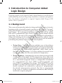
1 Introduction to Computer-Aided Logic Design Designing complex circuits typical of today’s digital hardware is possible because of the availability of tools for design entry, simulation, verification, and synthesis. Here, the student is introduced to a typical Computer-Aided Design (CAD) system, Altera’s Quartus II. 1.1Background Pr oo f This course will require the student to design and build a variety of circuits, beginning with conceptually simple ones that can be designed “by hand” using the techniques covered in a typical course on the theory of digital logic design. In a subsequent laboratory exercise, we will do exactly that with a combinational logic circuit, building it with simple discrete logic chips. By the end of the course, it will no longer be reasonable to design and develop circuits of the required complexity without relying on Computer Aided Design, or CAD tools. These tools provide the means of performing the primary stages of product development: Fi n al • Design Entry. Typically, there are multiple ways of describing a circuit, including graphical schematics and various text languages. A design can be entered using more than one method, since some components can be described graphically, while others can be described in text languages. It is often a matter of personal choice or corporate policy as to the exact method of design entry. • Design Synthesis. Sometimes the circuit is then prototyped with “commercial-off-the-shelf” (COTS) components, wires, and circuit boards. However, the CAD software is often used to generate layouts for a customized integrated circuit or configuration information for a programmable logic device (PLD) or field-programmable gate array (FPGA) to implement the design. PLDs and FPGAs can be thought of as chips with repositories of gates, flip-flops, and other devices waiting to be connected by a process of “programming” the desired interconnection network. But this is programming in the sense of loading configuration information, not writing a traditional computer program. Lab 1 KendallHuntDDLEdition.indb 1 11//00 :1:0 AM oo f • Functional Simulation. Without actually building the circuit, the design files can be simulated to see how they behave. This is the first part of design verification and requires the user to provide graphical waveforms or text files that describe how the simulated inputs change over time. The simulator then determines how the circuit outputs would change, given those inputs. Once a simulation is performed, the circuit outputs are compared with known correct values, thus verifying that the circuit behaves as expected. The inputs and corresponding outputs are sometimes called test vectors, since they can be viewed as a sequence of logic input vectors with the correct output vectors. Functional simulation can be done before knowing exactly how the design maps onto hardware, since it does not necessarily consider timing issues resulting from physical implementation. Pr • Timing Analysis and Simulation. Timing Analysis is a part of design verification where the user verifies that the circuit will run properly in a chosen hardware implementation. This often includes a more detailed simulation, called a Timing Simulation. In order to accomplish this, the design has to be fitted to a specific device, like an FPGA (or perhaps to multiple devices). Fi n al • Production. At this point, a design might be fabricated in small quantities to be tested or used as a component of a larger system. For our purposes, “production” amounts to configuring an FPGA device (loosely described as “downloading” or “programming” the file that determines how device resources are connected), or building a small prototype board with discrete chips. • Test. Finished products undergo testing as part of a quality assurance process, so that the end user receives a working device. In a large-scale production environment, some samples may receive more rigorous testing than others. Each of these CAD stages will be performed in this course, using the Altera Quartus II software and lab instruments. Often, the term compilation shows up as part of the design process. This is not compilation in the sense of compiling a program, and it is actually a nebulous combination of some of the earlier processes described above. When the CAD tools process the files resulting from design entry, this is typically called “compilation,” and it may generate files needed for simulation, verification, or synthesis (including “fitting” the design to the resources of a particular PLD). KendallHuntDDLEdition.indb Lab 1 11//00 :1:0 AM AND2 A B INPUT VCC INPUT VCC OUTPUT C inst ENTITY andgate IS PORT ( a : IN STD_LOGIC; b : IN STD_LOGIC; c : OUT STD_LOGIC ); END andgate; ARCHITECTURE a OF andgate IS BEGIN c <= a and b; END a; oo f -- An AND gate LIBRARY ieee; USE ieee.std_logic_1164.all; Pr Figure 1.1 Two different methods of design entry applied to a simple example, a single AND gate. At the top is a schematic entry (Quartus “BDF” file), and at the bottom is a VHDL entry. Fi n al Figure 1.1 shows a graphical or schematic entry representation of a single AND gate in Quartus II (top) and a textual representation of an AND gate (bottom). The textual representation is in the language known as VHDL, which will be used later in the course. VHDL is one of several languages supported by Quartus II, and is not proprietary to Altera – it can be processed by tools from other vendors, too. Even if you have no background in VHDL, you can probably recognize much of what is going on in the code. The ENTITY section describes the pins of the gate (inputs and outputs), and the ARCHITECTURE section defines the outputs in terms of the inputs. 1.2The DE2 board When you come to the laboratory, you will see one of two circuit boards: the DE2 or DE2-70 board, as illustrated in Figure 1.2. This board contains one of two programmable logic devices, the EP2C35F672C6 (on the “DE2” board) or the EP2C70F896C6 (on the “DE2-70” board), which are part of the Cyclone II family of Altera FPGAs. As described earlier, these are FPGAs Lab 1 KendallHuntDDLEdition.indb 11//00 :1:0 AM oo f USB slave Run/ Program switch RS-232 port Audio Composite in video in Audio out al Mic VGA out PS2 port Ethernet port JP1 header Fi n Power switch USB host Pr 9V DC USB in Blaster JP2 header FPGA LCD SD Card Seven-segment Displays LEDs IrDA External clock Slide switches Pushbuttons Figure 1.2 The DE2 board will be used to implement all but the simplest circuits in the weeks to come. KendallHuntDDLEdition.indb Lab 1 11//00 :1:10 AM Figure 1.3 The FPGA pin numbers are references to the rows and columns of pins on the back of the device (soldered to the DE2 board). oo f that are reconfigured, or loosely speaking, “programmed,” to interconnect their internal devices as specified in your design files. In addition to the FPGA, the DE2 boards include many different interface devices like switches, displays, memory, and external connectors. The major devices are indicated in the lower part of Figure 1.2. In particular, the shaded devices will be used in upcoming labs and are thus most important. Other components may be of interest for the final project. Fi n al Pr On the DE2 board, certain pins of the FPGA (see Figure 1.3) are permanently wired to these peripheral devices, and the most important connections are listed in Appendix C. These include the pushbuttons in Table C.1, the slide switches in Table C.2, and the light-emitting diodes (LEDs) in Table C.3. The Quartus software is designed to work with many other applications in addition to the DE2 boards. It is a general-purpose suite of tools, intended for use with any possible board that a designer could conceive. The DE2 designers chose certain pins for certain functions, based on FPGA limitations, distance between chips on the board, and other factors. When a design is synthesized and “fitted” to the FPGA, the fitter will use any convenient pin for inputs and outputs unless the user specifies otherwise. So when a resource like a switch or LED is to be used, it is critical to specify (or “assign”) a specific pin number to a specific input or output. You do not have to know the exact physical location of the tiny pin on the FPGA chip, but you do have to know the pin number in order to give your design access to the corresponding hardware. Throughout this course, logical zeros and ones will be implemented with voltage levels. Interpreting everything for now as positive logic, any voltage below a specific low logic threshold will represent logical 0, and anything above a specific high logic threshold will represent logical 1. The high and low logic thresholds are NOT the same value, which allows for a region of uncertainty. All functional logic gates should be capable of driving a low signal below the region of uncertainty, and a high signal above the region of Lab 1 KendallHuntDDLEdition.indb 11//00 :1:10 AM KEY[3] INPUT VCC PIN_W26 OUTPUT LEDG[7] PIN_Y18 Figure 1.4 A simple circuit that connects pin W26 of the FPGA to pin Y18 of the same chip. Since this circuit simply passes a signal through the device, none of the logic elements (LEs) will be used! oo f uncertainty, because there is no guaranteed behavior when an ambiguous voltage appears on a gate input. This will be discussed further in the next lab, but for now note that the DE2 board outputs will generally show low logic levels below 0.4 V and high logic levels above 2.4 V, both of which are better than what is required (i.e., more distant from the region of uncertainty than required). Fi n al Pr Note from the caption of Table C.1 that when a DE2 pushbutton switch is pressed, it results in a value of 0 for the corresponding signal. Such a switch is called an “active-low” switch, since it produces a low logic level when it is activated (pushed). The eighteen slide switches produce a 0 when in the down position (in the direction of the edge of the board). The slide switches have no off/on or active/inactive labels, so there’s no clear way to describe them as active-high or active-low. However, the DE2 LEDs (both the red ones and the green ones) are “active-high” in the sense that they will illuminate when driven with a 1, or a high signal. It is possible to create hardware with active-high pushbutton switches and active-low LEDs, but you should remember how these devices work on the DE2 board throughout the course (or at least know where to look to find out). Figure 1.4 shows a very trivial circuit created in the Quartus II schematic editor, which Altera calls the “Block Editor.” It simply illustrates how a user could force the compiler and fitter to use pin W26 (the KEY[3] pushbutton) as an input and connect it to pin Y18 (the green LED called LEDG[7]) as an output. Even though this example shows pin names that look like devices that they represent (KEY[3] and LEDG[7]), you must remember that Quartus knows nothing about these names and their significance on the DE2 board. It is only because the user has assigned the pins (to the values of PIN_W26 and PIN_Y18) that the correct pins are being used (see the pin assignments located near each pin). Confirm these pin numbers in the relevant tables of Appendix C, if you like. The actual pin assignments in a schematic are made by a process to be described in the instructions for this lab exercise. KendallHuntDDLEdition.indb Lab 1 11//00 :1:10 AM If you were to compile this design and configure the FPGA on the DE2 board with the resulting programming file, it would allow you to turn the specified LED on and off with the KEY[3] switch. You could predict what condition of the switch would turn on the LED, since the active levels were given earlier. (Pressing the switch results in a low logic level, and a low logic level should produce an unlit condition of the LED.) The other LEDs would be in some default state, unless you specifically tied them to power or ground. Even though the FPGA contains thousands of logic elements (see the textbook reading assignment in the prelab), none of them are needed for this circuit, which has no gates or flip-flops. As trivial as this example is, it illustrates exactly what Quartus II does — it connects chip resources together as the user specifies. Fi n al Pr oo f One last point of interest is that since many of the FPGA pins on the DE2 board are tied to dedicated devices, then it is important not to inadvertently use any FPGA pins that connect to this external hardware. One of the Quartus compiler options is to force all unused pins to a harmless input state, which will be the norm in all upcoming lab exercises with the DE2 board. Lab 1 KendallHuntDDLEdition.indb 11//00 :1:10 AM 1.3Prelab Steps For each laboratory exercise, the prelab steps MUST be completed before your lab section meets. This first laboratory includes reading assignments and computer exercises: 1. Complete the reading assignment: • Chapters 2 and 3 of Rapid Prototyping of Digital Systems, SOPC Edition (pp. 45-71), • Appendix A of this manual, “The Art of Debugging,” and oo f • Selected chapters of the DE2 User Manual, available on the course web site (specific to the version of the board being used in the lab). Even if you are unable to successfully install Quartus II, you must still perform any necessary prelab steps. You can do this by visiting the laboratory during open hours before your lab section meets, or by using any computer in the school that has Quartus II installed. You can also seek installation assistance in the lab, especially if you are able to bring your computer with you. (Failure to properly install the software at home will NOT excuse you from skipping the prelab steps, because open labs will be available.) Fi n al Pr 2. Install the Quartus II software by following instructions at the course web site. Do NOT install the version included on the CD in your textbook, since a newer version will be available. The instructions on the course web site will describe how to download Quartus II from the Altera web site, http://www.altera.com. 3. Complete sections B.1 and B.2 of the Quartus II tutorial located in Appendix B. 4. Bring to the lab a figure resembling that of Figure 1.5, as a printed hardcopy, with your name in the title block. To do this, begin with the resulting BDF file at the end of step 3 above. In the Quartus II Block Editor, add a “title” symbol from the “other” section of the “primitives” library. Double-click on the title block to edit the contents, changing the values to match those in KendallHuntDDLEdition.indb Lab 1 11//00 :1:10 AM Figure 1.4, except using your own name. Finally, select View => Show Location Assignments from the menu in order to see the pin assignments as shown in the figure, if they do not appear by default. Print the resulting schematic and bring it to your normal lab section meeting. To do this, select File => Export. . . and create a JPEG or BMP file that you import into Microsoft Word or print from various applications, or you can print directly if you have a connected printer. But remember the File => Export. . . technique, because it is the proper way to get readable figures from the Block Editor into Microsoft Word documents, which you will have to do later when a figure is part of a larger document or when you are required to format with borders and captions! If you have tools to manipulate PDF documents, you may also choose the option of printing to PDF from Quartus and subsequently importing the cropped PDF to other applications. () Pr oo f sw4 PIN_AF14 al OUTPUT INPUT VCC PIN_AD21 NOT INPUT VCC NOT Fi n inst1 inst2 inst sw5 PIN_AD13 d6 AND2 OR2 OUTPUT d3 PIN_AC22 inst4 AND2 inst3 OUTPUT d5 PIN_AD23 TITLE Quartus II Tutorial COMPANY Digital Design Laboratory George P. Burdell DESIGNER NUMBER DATE 1.00 Tue Jan 13 17:05:00 2009 REV SHEET 1 A OF 1 Figure 1.5 The result of the prelab exercises is a schematic similar to this, which each student should bring to the laboratory as a prelab checkoff. Lab 1 KendallHuntDDLEdition.indb 11//00 :1:10 AM Note! There are many methods for controlling the size and placement of figures in Word and in other word processing applications. Ask TAs for tips, if needed, and use whatever resources you have to master the use of your chosen application. You can drastically reduce the size of the directory you carry between machines by deleting the “db” and “incremental_db” subdirectories with all of their files. These directories are recreated as needed during recompilation. Certain other report and summary files can also be deleted, but you should err on the side of caution by not deleting files that may be necessary. Fi n al Pr oo f Tip! 5. Bring your entire project directory to class with you, either on removable media or by placing it in your home directory. The remaining steps are performed in the laboratory. 10 KendallHuntDDLEdition.indb 10 Lab 1 11//00 :1:11 AM 1.4Laboratory Steps The USB cable should be connected to the connector labeled BLASTER, not the neighboring one labelled DEVICE. It will not harm the board to connect it to JP11, but it will not work as described here! oo f Note! 1. Look at the DE2 board at the lab workstation. Find the FPGA, the slide switches SW0-SW17, the pushbuttons KEY0-KEY3, and the LEDs. The DE2 board receives power through a connector on the upper left, controlled by a red pushbutton switch located nearby. It is programmed from the PC through a USB cable that is probably already connected to the leftmost of two USB connectors on the left side of the top of the board. If you have any questions or concerns, ask a TA to show you how to properly connect cables and switch the board power on. Pr 2. If the Quartus II tutorial project from the prelab is not already available to you on your local disk, copy it at this time to a location where you can work on it in the laboratory. Fi n al 3. First, start Quartus II, if you have not already. From the menu, select File => Open Project…, find your “tutorial” directory, and open the “tutorial.qpf” project (or whatever names you used for the directory and project). Note that this makes the “tutorial.bdf” block editor file appear in the project hierarchy, and will probably open the editor automatically. (This depends on whether the editor was open when you saved the project. If the editor does not open automatically, then do so by double clicking the TUTORIAL. BDF file in the project hierarchy or opening it using the file menu.) 4. Resume where you left off in the Quartus II tutorial in Appendix B. When you have a successful functional simulation, according to the instructions in section B.3, request a checkoff from a TA. You will need a copy of this simulation for your results, but there is no option to export a graphic bitmap, as was done earlier with a schematic. Instead, either use the “PrtSc” (Print Screen) key, or print to a PDF, as shown in Figure 1.6. Either approach is acceptable. Both will require some cropping and possibly some resizing. Lab 1 KendallHuntDDLEdition.indb 11 11 11//00 :1:11 AM Date: August 09, 2009 tutorial.vwf 0 ps 80.0 ns Project: tutorial 160.0 ns 200.0 ns 10.375 ns sw4 sw5 d3 d5 d6 oo f Figure 1.6 It is possible to save images of simulation waveforms either with the “PrtSc” key (see Figure B.27 for an example), or by printing to a PDF file and manipulating the result with other applications, as shown here. Is the cursor a useful detail here? Figure 1.6 illustrates that it is easy to leave extraneous items in your screen graphics. The cursor at 10.375 ns shows nothing of interest. In your image, slide it off to 0 ns (or use it for something that is of interest and worth noting in a caption). Choose a method to capture (and retain) an image of the functional simulation results, showing all 200 ns of simulation time. () al Never distort the proportions of your figures as you resize them. Most graphic and word-processing applications have an option to resize proportionately. Often, it is simply holding down the Shift key while dragging the handles. Fi n Note! Pr 5. When you have a successful timing simulation (as in section B.3), request another checkoff from a TA, then capture (and again, retain) a copy of the new timing simulation results. () 6. Figure out which switches to move and what LED conditions to expect after downloading the design to the DE2 board. Ask a TA for a checkoff when you are able to show all four test conditions of the circuit. () 7. In the next laboratory exercise, you will use some of the chips from your chip set. Pick any one of those chips and find the datasheet for it. (Refer to the class web site for the datasheets or a link to the datasheets.) Read the datasheet to see how much you Page 1 of 1 12 KendallHuntDDLEdition.indb 1 Revision: tutorial Lab 1 11//00 :1:11 AM understand, find a page that shows a diagram of your package with pin numbers and their function (the pinout), and print that page as a checkoff. This may be the first page, or it may occur later in the datasheets. () 8. Every laboratory exercise has required results. For this laboratory, retain the following items for printing now or later, in this order: • The schematic for the circuit (from Prelab step 4). • The functional simulation results (from Lab step 4). oo f • The timing simulation results (from Lab step 5). • The pinout page of the datasheet for one of your chips (from Lab step 7). Do not format this page as a boxed figure or give it a caption. With the exception of the last item, all should be formatted according to the standards given by your graders (graduate teaching assistants and writing coordinator). Fi n al Pr Lab 1 KendallHuntDDLEdition.indb 1 13 11//00 :1:11 AM