1
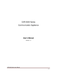
APC-PMC
PCI Bus PMC Carrier
USER’S MANUAL
ACROMAG INCORPORATED
30765 South Wixom Road
P.O. BOX 437
Wixom, MI 48393-7037 U.S.A.
Copyright 2005, Acromag, Inc., Printed in the USA.
Data and specifications are subject to change without notice.
Tel: (248) 295-0310
Fax: (248) 624-9234
8500-767-C12D003
2
APC-PMC User’s Manual
PCI Bus PMC Carrier
__________________________________________________________________
TABLE OF
CONTENTS
IMPORTANT SAFETY CONSIDERATIONS
You must consider the possible negative effects of power, wiring,
component, sensor, or software failure in the design of any type of
control or monitoring system. This is very important where property
loss or human life is involved. It is important that you perform
satisfactory overall system design and it is agreed between you and
Acromag, that this is your responsibility.
1.0 General Information
The information of this manual
may change without notice.
Acromag makes no warranty
of any kind with regard to this
material, including, but not
limited to, the implied
warranties of merchantability
and fitness for a particular
purpose. Further, Acromag
assumes no responsibility for
any errors that may appear in
this manual and makes no
commitment to update, or
keep current, the information
contained in this manual. No
part of this manual may be
copied or reproduced in any
form without the prior written
consent of Acromag, Inc.
KEY FEATURES…………...… …… …. … …… … …. .
3
2.0 PREPARATION FOR USE
UNPACKING AND INSPECTION...…………………...
CARD CAGE CONSIDERATIONS.........……………..
Rear I/O Connector……………….………………
Non-Isolation Considerations...........................
PCI Bus Connectors.……………………………..
3
3
4
4
5
3.0 SERVICE AND REPAIR
SERVICE AND REPAIR ASSISTANCE...……….…...
PRELIMINARY SERVICE PROCEDURE...…………..
WHERE TO GET HELP…………………………………
7
7
7
4.0 SPECIFICATIONS
PHYSICAL..................................................................
ENVIRONMENTAL....…….……………………………..
PCI LOCAL BUS INTERFACE...………………………
8
8
8
DRAWINGS
4502-032 APC-PMC Connector Diagram.........…….
9
Trademarks are the property of their respective owners.
__________________________________________________________________________
Acromag, Inc. Tel:248-295-0310 Fax:248-624-9234 Email:[email protected] http://www.acromag.com
APC-PMC User’s Manual
PCI Bus PMC Carrier
___________________________________________________________________
The APC-PMC is a PCI bus PMC module carrier designed for the 32-bit
PCI bus. The carrier enables the use of PCI mezzanine I/O modules in a
standard PCI computer system. The carrier card acts as an adapter to route
PCI bus signals between the PCI bus of your PC and the J1 and J2
connectors of a PMC module card.
3
1.0 GENERAL
INFORMATION
PMC modules with rear I/O are routed to rows A and C of a 64 pin DIN
41 612 signal connector on the APC-PMC card.
PMC modules with front I/O can be accessed though the PCI card face
plate.
Upon receipt of this product, inspect the shipping carton for evidence of
mishandling during transit. If the shipping carton is badly damaged or water
stained, request that the carrier's agent be present when the carton is
opened. If the carrier's agent is absent when the carton is opened and the
contents of the carton are damaged, keep the carton and packing material
for the agent's inspection.
2.0 PREPARATION
FOR USE
UNPACKING AND
INSPECTION
For repairs to a product damaged in shipment, refer to the Acromag
Service Policy to obtain return instructions. It is suggested that salvageable
shipping cartons and packing material be saved for future use in the event
the product must be shipped.
This board is physically protected with packing material and electrically
protected with an anti-static bag during shipment. However, it is
recommended that the board be visually inspected for evidence of
mishandling prior to applying power.
Refer to the specifications for loading and power requirements. Be sure
that the system power supplies are able to accommodate the power
requirements of the system boards, plus the installed Acromag board, within
the voltage tolerances specified.
Adequate air circulation must be provided to prevent a temperature rise
above the maximum operating temperature and to prolong the life of the
electronics. If the installation is in an industrial environment and the board is
exposed to environmental air, careful consideration should be given to airfiltering.
WARNING: This board utilizes
static sensitive components
and should only be handled at
a static-safe workstation.
CARD CAGE
CONSIDERATIONS
IMPORTANT: Adequate air
circulation must be
provided to prevent a
temperature rise above the
maximum operating
temperature.
Remove power from the system before installing board, cables,
termination panels, and field wiring.
__________________________________________________________________________
Acromag, Inc. Tel:248-295-0310 Fax:248-295-0310 Email:[email protected] http://www.acromag.com
4
APC-PMC User’s Manual
PCI Bus PMC Carrier
__________________________________________________________________
Rear I/O Connector
The P2 rear connector provides 64 field I/O interface connections to the
J4 connector of the PMC module. The P2 connector is a 64-pin DIN 41 612
male connector (Harting 09 09 164 6922 or equivalent) using rows A and C.
Table 2.1: Board Field I/O Pin
Connections
Non-Isolation
Considerations
P2 Row C Pin
1
2
3
4
5
6
7
8
9
10
11
12
13
14
15
16
17
18
19
20
21
22
23
24
25
26
27
28
29
30
31
32
J4 Pin
1
3
5
7
9
11
13
15
17
19
21
23
25
27
29
31
33
35
37
39
41
43
45
47
49
51
53
55
57
59
61
63
P2 Row A Pin
1
2
3
4
5
6
7
8
9
10
11
12
13
14
15
16
17
18
19
20
21
22
23
24
25
26
27
28
29
30
31
32
J4 Pin
2
4
6
8
10
12
14
16
18
20
22
24
26
28
30
32
34
36
38
40
42
44
46
48
50
52
54
56
58
60
62
64
The board is non-isolated, since there is electrical continuity between the
PCI bus and PMC module grounds. As such, the field I/O connections are
not isolated from the system. Care should be taken in designing
installations without isolation to avoid noise pickup and ground loops caused
by multiple ground connections.
__________________________________________________________________________
Acromag, Inc. Tel:248-295-0310 Fax:248-624-9234 Email:[email protected] http://www.acromag.com
APC-PMC User’s Manual
PCI Bus PMC Carrier
___________________________________________________________________
Table 2.2 indicates the pin assignments of the PCI bus signals at the
card edge (P1) connector. The connector pins are designated by a letter
and a number. The letter indicates which side of the connector the pin
contact is on. “B” is the component side of the board while “A” is the solder
side . Connector “gold finger” numbers increase with distance from the
bracket end of the printed circuit board. Table 2.2 also lists the P1 signals
and to which PMC J1 or J2 pins they are routed. Five volt and 3.3 volt
power and ground connections between the P1, J1, and J2 connector are
routed on power and ground planes.
Signal
-12V
TCK
Ground
TDO
+5V
+5V
INTB#
INTD#
PRSNT1#
Reserved 2
PRSNT2#
+3.3V KEYWAY
P1 to J1 or J2 Pins
B01 / J1-2
B02 / J1-1
B03 / J1-3
B04 / J2-4
B05 / J1-8
B06 / 5V Plane
B07 / J1-5
B08 / J1-9
B09 (Pulled Low)
B10 / J2-9
B11 (Pulled Low)
P1 to J1 or J2 Pins
A01 / J2-2
A02 / J2-1
A03 / J2-3
A04 / J2-5
A05 / J1-30
A06 / J1-4
A07 / J1-6
A08 / 5V Plane
A09 / J2-8
A10 / VIO 40 mil Trace
A11 / J2-10
+3.3V KEYWAY
Reserved 4
Ground
CLK
Ground
REQ#
+VIO
AD[31]
AD[29]
Ground
AD[27]
AD[25]
+3.3V
C/BE[3]#
AD[23]
Ground
AD[21]
AD[19]
+3.3V
AD[17]
C/BE[2]#
Ground
IRDY#
+3.3V
DEVSEL#
PCIXCAP
LOCK#
PERR#
+3.3V
SERR#
+3.3V
C/BE[1]#
AD[14]
Ground
AD[12]
AD[10]
Ground
Signal
TRST#
+12V
TMS
TDI
+5V
INTA#
INTC#
+5V
Reserved 1
+VIO
Reserved 3
+3.3V KEYWAY
5
PCI Bus Connectors
Table 2.2: PCI Bus P1
Connections
Bracket End ↑
+3.3V KEYWAY
B14 / J1-10
B15 / Ground Plane
B16 / J1-13
B17 / Ground Plane
B18 / J1-17
B19 / 40 mil Trace
B20 / J1-20
B21 / J2-20
B22 / Ground Plane
B23 / J1-22
B24 / J1-23
B25 3.3V Plane
B26 / J1-26
B27 / J2-26
B28 / Ground Plane
B29 / J1-28
B30 / J1-29
B31 3.3V Plane
B32 / J1-32
B33 / J2-32
B34 / Ground Plane
B35 / J1-36
B36 3.3V Plane
B37 / J1-37
B38 / Ground Plane
B39 / J1-40
B40 / J2-39
B41 3.3V Plane
B42 / J2-42
B43 3.3V Plane
B44 / J2-43
B45 / J2-45
B46 / Ground Plane
B47 / J1-47
B48 / J2-48
B49 / Ground Plane
A14 (No Connect)
A15 / J2 13
A16 / VIO Plane
A17 / J1-16
A18 / Ground Plane
A19 / J2-17
A20 / J2-19
A21 3.3V Plane
A22 / J1-21
A23 / J2-22
A24 / Ground Plane
A25 / J2-23
A26 / J2-25
A27 3.3V Plane
A28 / J1-27
A29 / J2-28
A30 / Ground Plane
A31 / J2-29
A32 / J-31
A33 3.3V Plane
A34 / J1-33
A35 / Ground Plane
A36 / J2-35
A37 / Ground Plane
A38 / J2-38
A39 3.3V Plane
A40 / J1-41
A41 / J1-42
A42 / Ground Plane
A43 / J1-43
A44 / J1-46
A45 3.3V Plane
A46 / J2-46
A47 / J1-48
A48 / Ground Plane
A49 / J1-49
3.2Vaux
RST#
+VIO
GNT#
Ground
PME#
AD[30]
+3.3V
AD[28]
AD[26]
Ground
AD[24]
IDSEL
+3.3V
AD[22]
AD[20]
Ground
AD[18]
AD[16]
+3.3V
FRAME#
Ground
TRDY#
Ground
STOP#
+3.3V
SMBCLK
SMBDAT
Ground
PAR
AD[15]
+3.3V
AD[13]
AD[11]
Ground
AD[09]
__________________________________________________________________________
Acromag, Inc. Tel:248-295-0310 Fax:248-295-0310 Email:[email protected] http://www.acromag.com
6
APC-PMC User’s Manual
PCI Bus PMC Carrier
__________________________________________________________________
Signal
5V KEYWAY
P1 to J1 or J2 Pins
P1 to J1 or J2 Pins
5V KEYWAY
AD[08]
B52 / J2-49
AD[07]
B53 / J2-51
+3.3V
B54 3.3V Plane
AD[05]
B55 / J1-54
AD[03]
B56 / J1-58
Ground
B57 / Ground Plane
AD[01]
B58 / J1-60
+VIO
B59 / 40 mil Trace
ACK64#
B60 / J2-61
+5V
B61 5V Plane
+5V
B62 5V Plane
(#) s used to indicate an active-low signal.
3.0 SERVICE AND
REPAIR
SERVICE AND REPAIR
ASSISTANCE
PRELIMINARY SERVICE
PROCEDURE
CAUTION: POWER MUST
BE TURNED OFF
BEFORE REMOVING OR
INSERTING BOARDS
Signal
5V KEYWAY
5V KEYWAY
A52 / J1-52
A53 3.3V Plane
A54 / J1-53
A55 / J1-55
A56 / Ground Plane
A57 / J1-59
A58 / J1-61
A59 / 40 mil Trace
A60 / J1-64
A61 5V Plane
A62 5V Plane
C/BE[0]#
+3.3V
AD[06]
AD[04]
Ground
AD[02]
AD[00]
+VIO
REQ64#
+5V
+5V
Surface-Mounted Technology (SMT) boards are generally difficult to
repair. It is highly recommended that a non-functioning board be returned to
Acromag for repair. The board can be easily damaged unless special SMT
repair and service tools are used. Further, Acromag has automated test
equipment that thoroughly checks the performance of each board. When a
board is first produced and when any repair is made, it is tested, placed in a
burn-in room at elevated temperature, and retested before shipment.
Please refer to Acromag's Service Policy Bulletin or contact Acromag for
complete details on how to obtain parts and repair.
Before beginning repair, be sure that all of the procedures in Section 2,
Preparation For Use, have been followed. Also, refer to the documentation
of your PMC module to verify that it is correctly configured. Replacement of
the board with one that is known to work correctly is a good technique to
isolate a faulty board.
WHERE TO GET HELP
If you continue to have problems, your next step should be to visit the
Acromag worldwide web site at http://www.acromag.com. Our web site
contains the most up-to-date product and software information.
www.acromag.com
An email question can also be submitted from the “Contact Us” tab.
Acromag’s application engineers can also be contacted directly for
technical assistance via telephone or FAX through the numbers listed at the
bottom of this page. When needed, complete repair services are also
available.
__________________________________________________________________________
Acromag, Inc. Tel:248-295-0310 Fax:248-624-9234 Email:[email protected] http://www.acromag.com
APC-PMC User’s Manual
PCI Bus PMC Carrier
___________________________________________________________________
7
4.0
SPECIFICATIONS
Length
Height
Board Thickness
6.6 inches (167.64 mm)
4.2 inches (106.68 mm)
0.063 inches (1.6 mm)
P1 (PCI Bus) PCI Specification 2.3 5V/3.3V board card edge finger
spacing.
J1 and J2 PMC PCI bus connectors interface to P1 connector. J1 and
J2 are Molex 71439-0164 or equivalent.
P2 Rear I/O connector with 64 pins of rows A and C interfaces to J4 of
PMC module (DIN 41 612 Harting 09 03 164 6922 or equivalent).
J4 PMC Rear I/O interfaces to P2 connector (Molex 71439-0164 or
equivalent).
Operating Temperature: –40 C to +85 C
Relative Humidity: 5-95% Non-Condensing.
Storage Temperature: -55 C to 125 C.
Non-Isolated: PCI bus and field commons have a direct electrical
connection.
PHYSICAL
Connectors
ENVIRONMENTAL
PCI Local Bus Interface
PMC Compatibility: Pin assignment conform to PCI Bus Specification,
Revision 2.3 and PMC Specification, P1386.1
Signaling: 5V or 3.3V as required by the PMC module.
PCI Bus Clock: This product is not guaranteed to function with a PCI bus
clock frequency greater than 33MHz.
__________________________________________________________________________
Acromag, Inc. Tel:248-295-0310 Fax:248-295-0310 Email:[email protected] http://www.acromag.com
4502-032
8
APC-PMC User’s Manual
PCI Bus PMC Carrier
__________________________________________________________________
__________________________________________________________________________
Acromag, Inc. Tel:248-295-0310 Fax:248-624-9234 Email:[email protected] http://www.acromag.com