1
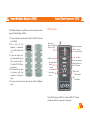
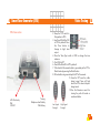
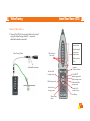
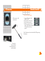
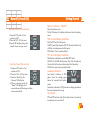
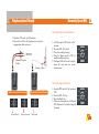
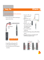
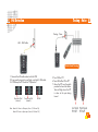
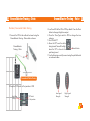
240 HAL : High quality Tone
Generator with add on to test
CATV / COA
Advanced Testers Kit
CATV/Model1: A perfect solution
to tone CATV cables using
conventional toners and probes
Galaxy Craft Test Set: A value
for money product that meets the
most demanding technical needs
Replacement cables for any product
AINES
MANUFACTURING CORP.
www.aines.com
Quality manufacturing and
service for over 5 decades
[email protected]
User Manual
Congratulations!
You are now a proud owner of Aines Advanced Testers Kit.
A digital device kit designed for Professional testing of Voice,
Data, Video and Security networks.
Aines Manufacturing Corporation has been servicing the
telecommunications industry worldwide for over five decades.
We are in The Hamptons in Long Island, New York. All our
products are designed and manufactured to exacting
standards and tolerances. Our customers cover the entire
gambit of the telecommunications industry throughout the
world.
350 FP: The best Noise Filter probe with all
features that a technician can ask for - including a
headset jack for use in both noisy as well as office
environments.
24 Index
Overview 1
1.
Lanyard, 3
Low battery, 3, 11, 13, 15, 40 ,43
Low signal strength, 21, 23, 25,
27, 37
Smart Modular Adaptor, 3, 7, 38
Straight, 3, 15, 16, 20
T
2.
M
3.
NO - NC Cable, 9, 16, 30, 33, 41
noise-filter, 3
Normally Open, 11, 30, 31, 32,
Normally Closed, 11, 33, 34, 35
Talk battery, 3, 12, 15, 16, 19, 39,
41
Telephone line polarity, 11, 12, 18
Tone Type switch, 20, 23, 25, 27,
37
Tone button, 27, 23, 24, 37
Tracing - Data, 6, 8, 16, 24, 25,
26, 27
Tracing - Video, 6, 8, 16
Tracing - Voice, 6, 8, 16, 18, 20,
21, 22, 23, 41
P
V
8.
Pass, 15, 20
Patch panel tracing, 3, 21, 25
PoE, 3, 6, 9, 12, 16, 20, 28, 40,
41
Polarity reversed, 20
Volume, 3, 13
Mode button, 32
Momentary, 3, 11, 34
N
S
Safety Instructions, 43
Security networks, 3
Short, 20
W
Warranty, 44
4.
5.
6.
7.
9.
10.
11.
12.
13.
14.
All in one kit for Voice
network, Data network,
Video network and
Security network
23 different tests and
more
11 cables for various tests
in Voice, Data, Video and
Security networks
High quality noise-filter
for better tone output
Integrated inductive tip on
probe for tracing
Patch panel tracing
Concealed, overhead
cable tracing using
Groundblaster technology
Extension wand for buried
and overhead cable
tracing
Shielded cable tracing
using Groundblaster
technology
Eight cadence pattern for
tracing
Digital volume control
Selectable high - low tone
output
LAN continuity testing
Straight - Cross cable
identification
15. Open - Short cable
identification
16. Telephone polarity testing
17. PoE detection
18. Talk battery
19. Security tests in
Instantaneous, Steady
and Momentary modes
20. Smart Modular Adaptor
for customised testing
21. Auto shutoff only after
one hour to prevent
nuisance shut off
22. Low battery indication
23. Special cable for
grounding
24. Braided cables for longer
life
25. Telecom grade bed-ofnails clip, three way
26. Hard plastic shell with
rubber molding to
protect from accidental
falls
27. Splash proof, weather
proof carry case
28. Spare battery storage
provision in carry case
29. Lanyard for convenient
holding and operation
3
Index 24
Smart Tone Generator
Smart Tone Tracer
A
C
R
O
N
Y
M
S
&
A
B
B
R
E
V
I
A
T
I
O
N
S
Smart Modular Adaptor
Local Area Network
Power over Ethernet
8Positions - 6Contacts
Normally Open
Normally Closed
Talk Off Test
Light Emitting Diode
Kilo Hertz
Kilo Ωhms
deciBel Sound Pressure Level
6
6 pin, 38
8
8 pin, 16
8P - 6C Cable, 16
9
9V battery, 15, 39
A
alligator clips, 30, 33, 38
audible reporting, 31
Auto shutoff, 3, 15, 39
B
bed-of-nails clip, 3
Beep, 10, 15, 31, 32, 34, 35
Braided cables, 3
bunch of cables, 21, 25
C
cadence, 3, 10, 11, 23, 25, 27,
37, 39
carry case, 3, 8
Coaxial cable, 3
Correct Polarity, 18
Cross, 3, 15, 20
E
Extension wand, 3, 7, 14, 23, 27,
37
G
General Purpose Cable, 18, 19,
24, 29
Groundblaster, 7, 9, 18, 25, 30
grounding, 3, 7, 9, 15
Grounding Cable, 7, 9, 16
H
High signal strength, 23, 25, 27,
37
I
Instantaneous, 3, 10, 31, 32, 34
Integrated inductive tip, 3
L
LAN cable, 28
45
Contents
23 Warranty
Aines Advanced Testers Kit carries a 30 month WARRANTY.
Our products have been honed to achieve results and are
thoroughly designed, engineered and tested by experts under
real-world conditions.
If the Aines product fails due to a manufacturing defect or fails
to give proper length of service, excluding normal wear and
tear, it will be replaced at Aines discretion. Warranty does not
cover cables, extension wand, battery, carry case, foam
padding. Warranty does not cover parts or products that are
improperly used, altered or repaired.
1
2
3
4
5
6
7
8
9
10
11
12
13
14
15
16
17
18
19
20
21
22
23
24
Overview
Acronyms and Abbreviations
Kit Contents
Smart Tone Generator (STG)
Smart Tone Tracer (STT)
Getting Started
Selecting the right Cable
Telephone Line Polarity Tests
Talk Battery
Tracing - Voice
Groundblaster Tracing - Voice
Tracing - Data
Groundblaster Tracing - Data
PoE Detection
LAN Continuity
Normally Open (NO)
Normally Closed (NC)
Video Tracing
Smart Modular Adaptor (SMA)
Technical Specifications
FAQ
Safety Instructions
Warranty
Index
3
4
6
10
13
15
16
18
19
20
22
24
26
28
29
30
33
36
38
39
40
43
44
45
5
What’s
What?
Tracing Data
Safety Instructions 22
LAN - PoE
8P - 6C
Warning
1. Never use the STG or STT on circuits of more than 60 V.
2. Never open the STG or STT except to change the
battery. No user-serviceable parts inside.
3. Turn off STG and STT and disconnect all test leads
before replacing the battery.
4. Use only a 9 V battery.
5. If this equipment is used in a manner not specified by
the manufacturer, the protection provided by the
equipment may be impaired.
Groundblaster
Tracing Data
Tracing Video
Groundblaster
Tracing Voice
Caution
NO - NC
Tracing Voice
1. Avoid touching the probe tip to patch panel connections
and using the tip to dig into cable bundles. Doing so
regularly may damage the probe tip over time.
2. To avoid unreliable test results, replace the battery as
soon as the low battery indication appears.
Batteries
Quick Reference
Guide
43
21 TIPS
Tracing
Positive signal is injected on
a wire and negative signal
is injected on another wire
of the cable from STG
When the cable to be
traced is at a long distance
the positive and negative
cancel each other and no
tone will heard
Groundblaster Tracing
Smart Tone Generator
STG
Only a positive signal is
injected on one wire from
STG
Other signal is connected to
ground this increases the
signal strength
When held close to the
cable you will be able to
hear an audible tone
A loud signal will be heard
even when traced from a
distance of up to 3 feet
from the cable
Ideal for identification of
port on patch panel, DP box
or identification of a pair or
cable in a bunch
Ideal for tracing cables that
are concealed, buried and
shielded
Smart Tone Tracer
STT
Smart
Modular
Adaptor
SMA
Grounding
Cable
Tone Mode VS Shield Mode in STT
Most units in the market work only with open cable, not connected
to any circuit. If the wire or shield of the cable is grounded on the
distant end, the cable cannot be traced
The STT detects a tone in two ways - capacitive and inductive
Tone (Capacitive)
When the distant end of the
cable is not terminated or
connected
General
Purpose
Cable
Extension
Wand
Shield (Inductive)
When the wire or shield of the
cable is grounded on the
distant end
7
3 Cables
FAQ 21
Tracing - Voice
Groundblaster™ Tracing - Voice
NO - NC test
not working
1. Make sure the TOT
switch is in test position.
2. Press the NO - NC
button
3. Use NO - NC cable
(Page 30)
1. Make sure the TOT
switch is in OFF position.
2. Use General Purpose
Cable or Tracing - Voice
cable (Page 18)
Telephone polarity
test
PoE detection
1. Make sure the TOT
switch is in OFF position.
2. Use the LAN - PoE
cable (Page 28)
1. Make sure the TOT
switch is in Talk position
2. Use general purpose
cable (Page 19)
Talk Battery
Tracing - Data
Groundblaster™Tracing - Data
Tracing - Video
41
Cables 3
21 FAQ
LAN - PoE Cable
Unit is dead
1. Check if the battery is
installed properly
2. Replace battery and
check
1. Check if low battery
indication is on.
Change batteries
2. Switch off the unit and
turn it on again
Buttons not
working
No tone
while tracing
1.Make sure the TOT switch
is in test position
2.Select high tone in STG
and switch between
tone/shield modes in
STT
3.Use the right cable (Page
16)
1. Make sure the TOT
switch is in test position
2. Select LAN mode.
3. Use the LAN - PoE
cable (Page 29)
NO - NC Cable
General Purpose Cable
LAN continuity test
not working
Grounding Cable
8P - 6C Cable
9
1
4 Smart Tone Generator (STG)
Technical Specifications
20
STG - Electrical
STG Controls
Switch between
talk, off,
test modes
Switch between
8 cadence Patterns
Switch between
‘Steady’, ‘Moment’
and ‘Instantaneous’
Reset ‘Steady’ mode
result
Toggles between
high and low
Toggles between
NO - NC Modes
On/Off beep sound
during security tests
LAN
continuity tests
FEATURE
SPECIFICATION
1
Power requirement
Standard 9V battery
2
Tone frequency
1 KHz
3
Tone cadence
8
4
High Tone Output
30V peak to peak
5
Low Tone Output
15V peak to peak
6
Talk battery into 600 Ω
5.5V DC
7
Auto shutoff
After 1 hour
8
NC circuit testing
<1.5 KΩ
9
NO circuit testing
>1.5 KΩ
STT - Electrical
FEATURE
SPECIFICATION
1
Power requirement
Standard 9V battery
2
Tone frequency detection
1 KHz
3
Auto shutoff
After 1 hour
4
Tone Output level
>125 dB SPL
5
Provision for wand
Available
STG And STT - Physical
1
DIMENSION
Length
STG
125 mm
STT
182 mm
2
Width
68 mm
42 mm
3
Height
26 mm
33 mm
4
Weight
160 gm
150 gm
39
11
Smart Tone Generator (STG) 4
19 Smart Modular Adaptor (SMA)
The Modular Adapter is useful if you want to connect to certain
pins of a Modular Plug or Outlet.
1. Connect the cable (under test) to either of the RJ-45 socket
on the SMA.
2. O n e s i d e o f t h e
adapter is numbered
1-6 and the other side
1-8.
3. If you are testing a 6
pin connector then use
the 1-6 side. Use the 18 side for RJ-45 8 pin
connectors.
4. The terminals are easy
to connect with the
s uppl i e d Al l i gator
clips.
5. You may also connect any other device that has Alligator
clips.
STG Indicators
Presence of
Power over Ethernet
(Green or Red)
High Tone
Normally Open
mode
Steady
mode
Momentary
mode
Telephone line polarity
Green - correct
Red - reversed polarity
Low Tone
Shows tone cadence
Indicates failures in
NO - NC modes
Normally
Closed mode
Low battery
Note: While testing a LAN, the indicators NO, NC, Steady
and Moment blink in sequence continuously
11
12
Video Tracing 18
4 Smart Tone Generator (STG)
STG Connectors
LAN Continuity
PoE
NO-NC
2. Keep the TOT switch in
Test position in STG
3. Low Tone LED will be ON
in STG by default. Press
the 'Tone' button to
change to high tone
output
4. Press the 'Tone Type' switch in STG to change the tone
cadence
5. Turn ON the STT
6. Tone LED will be ON in STT by default
7. If the shield of the coaxial cable is grounded put the STT in
Shield mode by pressing the Shield button
8. If the shield is not grounded put the STT in Tone mode
9. Move the STT near the cable
being traced. Tone will high
when the STT is close to the pair
being traced
10.Use the Extension wand for
tracing the path of buried or
overhead cables
Tracing
Telephone Line Polarity
Talk Battery
Low Signal
Strength
High Signal
Strength
37
Smart Tone Tracer (STT) 5
18 Video Tracing
Coaxial Cable Tracing
1. Connect the STG to the co-axial cable to be traced
using the Video Tracing Cable (F - connector,
detachable female connector)
Volume level
LAN continuity
test results
Video Tracing Cable
Signal strength
in tone and
shield mode
LAN continuity
Tests
Detachable connector
Activate LAN
testing mode
LAN testing mode
Activate tone
tracing mode
Speaker
Volume Control
On/Off STT
Activate grounded
shield tracing mode
Grounded shield
tracing mode
Restart LAN
continuity tests
Low battery
Tone tracing
Mode
13
Normally Closed (NC) 17
4 STT Connectors
Normally Closed (Steady)
RJ45 connector - LAN
continuity tests
1. Keep the TOT switch in 'Test'
position in STG
2. Press the 'NO - NC' key twice
3. Press the 'Mode' key twice
4. If there is an open circuit, the
“Report” LED will glow along with
the beep till the reset key is
pressed
Note: The beep sound can be switched On/Off by pressing
the beep key
Provision for
Extension Wand
for checking buried or
overhead cables
35
Getting Started 6
17 Normally Closed (NC)
Battery installation – STG/STT
Normally Closed (Instantaneous)
1. Keep the TOT switch in 'Test'
position in STG
2. Press the 'NO - NC' key twice
3. Report LED will glow along with
beep if there is an open circuit
Open the battery cover
Fix the 9V battery in the battery holder and close the battery
cover
STG - To Check Battery Installation
Push the TOT switch to Test mode
All LED’s (Low, High, Report, NO, NC, Steady and Moment)
will blink and a beep sound will be heard
STG will be in ‘Tone’ mode by default
STT - To Check Battery Installation
Normally Closed (Momentary)
1. Keep the TOT switch in 'Test'
position in STG
2. Press the 'NO - NC' key twice
3. Press the 'Mode' key, the
'Moment' LED will glow
4. If there is an open circuit, the
“Report” LED will glow for 2
seconds along with the beep and then
resets automatically
After battery installation press the ON/OFF switch
All LED’s (In the LED indication bar, Pass, Fail, Straight and
Cross) will blink three times (takes about 3 to 5 seconds).
STT will be in tone tracing mode by default
Low Battery Indication
Low battery indication in STG
glows when the voltage goes
below the required talk battery
power
Low battery indication in STT glows when voltage goes below
the required power for tracing
Auto Shutoff
STT and STG will auto shut off only after an hour of inactivity
to avoid any nuisance shut off
15
9
Normally Closed (NC) 17
7 Selecting the right cable
CABLE
TESTS
Normally Closed
Patch panel tracing (Page 21)
Identifying the correct pair
Polarity testing (Page 18)
1
Tracing - Voice
2
Groundblaster Tracing - Voice
3
Tracing - Data
Patch panel tracing
Identifying a cable in a bunch
4
Groundblaster Tracing - Data
Shielded, concealed, buried,
overhead cable tracing
5
Tracing - Video
Concealed, buried, overhead cable
tracing
Coaxial cable tracing
LAN continuity testing - Straight,
Cross identification
PoE detection
6
LAN - PoE
7
NO - NC cable
Security, alarm network testing
8
General Purpose Cable
Talk battery
Unterminated cable tracing
Polarity testing on unterminated
telephone lines
9
Grounding Cable
10
8P - 6C Cable
NO - NC Cable
For grounding during
Groundblaster tracing
Continuity tests to be used with
SMA
1. Connect the STG to the points to be tested using the NONC cable
2. Connect the alligator clips to the end-points to be tested
33
16 Normally Open (NO)
Normally Open (Steady)
1. Keep the TOT switch in 'Test' position
in STG
2. Press the 'NO - NC' switch
3. Press the 'Mode' button twice to
activate 'Steady' Mode
4. If there is closed circuit, the “Report”
LED will glow continuously along
with the beep till the reset key is
pressed
ELABORATED
PROCEDURES
Note: Press the mode key to go back to Normally Open (instantaneous)
mode. The beep sound can be switched On/Off by pressing the Beep
switch
17
9
Normally Open (NO) 16
8 Telephone Line Polarity
Normally Open (Instantaneous)
1. Keep the TOT switch in OFF position
2. Connect the STG to the telephone line using the
appropriate cable as shown
General Purpose
Cable
Tracing - Voice
1. In STG, keep the TOT switch in 'Test'
position
2. Press the 'NO - NC' switch
3. The unit is ready for testing
4. Press the 'Beep' switch in STG to
enable audible reporting
5. The Report LED will turn off and the
beep will stop when the circuit
become open
Normally Open (Moment)
Unterminated Cable Testing
Correct Polarity
Polarity Reversed
Terminated Cable Testing
Cable Dead
1. Keep the TOT switch in 'Test' position in
STG
2. Press the 'NO - NC' key
3. Press the 'Mode' key
4. If there is a closed circuit, the “Report”
LED will glow for 2 seconds along with
the beep
31
19
9
16 Normally Open (NO)
Talk Battery 9
Normally Open
1. STG can power the telephone cable. This enables
technicians to test the cable using a Buttset
2. Connect the STG to the dead cable using General Purpose
cable as shown below
3. Keep the TOT switch in talk position
4. Now the technicians can go off-hook and talk to each other
NO - NC Cable
General Purpose
Cable
1. Connect the STG to the points to be tested using the NONC cable
2. Connect the alligator clips to the end-points to be tested
Note: This operation consumes more battery power
19
LAN Continuity 15
10 Tracing - Voice
Unterminated Cable Tracing, Patch Panel Identification
1. Connect the STG to the cable to be traced using an
appropriate cable as shown
General Purpose
Cable
1. Connect the STG to the
wall jack using the LAN PoE cable
2. Keep the TOT switch in
LAN - PoE Cable
“Test position” and press
LAN switch
3. Connect the STT to the
other end of the cable from
the wall jack using the
other LAN - PoE cable
4. Turn on the STT and press
the LAN switch
5. In STG, the NO, NC, Steady and Moment LED's will blink in
sequence
6. To repeat the continuity test, press the 'R' key in the STT.
At the STG end, no operation is needed
Unterminated Cable Tracing
2. Keep the TOT switch in Test position in STG
3. Low Tone LED will be ON in STG by default
4. Press the 'Tone Type' switch in STG to change the
tone cadence
Pass,
Straight
Shield Connectivity
Present
Open
Wire
Fail
Short
Wire
Fail
Pass,
Cross
29
Tracing - Voice 10
14 PoE Detection
Tracing - Voice
LAN - PoE Cable
Patch Panel Tracing
1. Connect the LAN cable under test to the STG
2. If you need to connect to a wall jack, use the LAN - PoE cable
3. In STG keep the TOT switch in “Off position”
Presence of PoE
(Mode A)
Presence of PoE
(Mode B)
No PoE
5. Turn ON the STT
6. Tone LED will be ON in STT
7. Move the STT over the patch
panel or the bunch of cables.
Tone will high when the STT
is close to the pair being
traced
Note: Mode A - Power in Data pair (Lines 1,2 & Lines 3,6)
Mode B - Power in Spare pair (Lines 4,5 & Lines 7,8)
21
11 Groundblaster Tracing - Voice
Concealed Cable Tracing
1. Connect the STG to the cable to be traced using the
Groundblaster Tracing - Voice cable as shown
Groundblaster
Tracing - Voice
Groundblaster Tracing - Data 13
3. Low Tone LED will be ON in STG by default. Press the 'Tone'
button to change to high tone output
4. Press the 'Tone Type' switch in STG to change the tone
cadence
5. Turn ON the STT. Tone LED will
be ON in STT by default
6. Move the STT near the cable
being traced. Tone will high
Default Mode
when the STT is close to the pair
being traced
7. Press the Shield button on STT if the shield of the cable is
grounded
8. Use the Extension wand if you are tracing the path of buried
or overhead cables
2. Keep the TOT switch in Test position in STG
High Tone
Output
TOT Switch
in Test position
Low Signal
Strength
High Signal
Strength
27
13 Groundblaster Tracing - Data
Shielded, Concealed Cable Tracing
1. Connect the STG to the cable to be traced using the
Groundblaster Tracing - Data cable as shown
Groundblaster
Tracing - Data
Groundblaster Tracing - Voice 11
3. Low Tone LED will be ON in STG by default. Press the 'Tone'
button to change to high tone output
4. Press the 'Tone Type' switch in STG to change the tone
cadence
5. Turn ON the STT
6. Move the STT near the cable
being traced. Tone will be high
Default Mode
when the STT is close to the
pair being traced
7. Use the Extension wand if you are tracing the path of buried
or overhead cables
Concealed Cable Tracing
2. Keep the TOT switch in Test position in STG
High Tone
Output
TOT Switch
in Test position
Low Signal
Strength
High Signal
Strength
23
Patch Panel Tracing