1
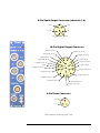
TDAS PRO
Timed Output Module
Hardware User’s Manual
December 2002 Rev. 1A
Table of Contents
Introducing the Timed Output Module ............................ 4
Summary of Module Features ........................................................................... 4
Basic Care and Handling .................................................................................. 4
Shock Rating.........................................................................................................................5
Temperature Rating ...............................................................................................................5
Power Connections and Considerations ........................................................... 5
Internal Module Back-up Batteries.........................................................................................5
Back-up Battery Operational Life ..........................................................................................6
Power Consumption and Management ....................................................................................6
Timing Functions .............................................................................................. 7
Squib Channel Overview ................................................................................... 7
DC Capacitive Discharge.......................................................................................................7
AC Capacitive Discharge.......................................................................................................7
DC Constant Current............................................................................................................8
Digital Channel Overview ................................................................................. 8
Contact Closure Mode............................................................................................................9
0 - 5 Volt (logic) Mode..........................................................................................................9
Squib Resistance Test ......................................................................................10
Test Article ID ..................................................................................................10
Safety and Arming Functions ........................................................................... 11
Safety Protocol .................................................................................................................... 11
Warning Systems ................................................................................................................ 11
Event Input ....................................................................................................... 11
Review of Recording Modes.................................................................................................. 12
Squib Data Recording Functions .....................................................................13
Squib Current Measurement ............................................................................................... 13
Squib Voltage Measurement ............................................................................................... 13
Channel Numbering ........................................................................................................... 13
ii
Appendix...........................................................................................................14
TOM Connector Information .............................................................................................. 14
15-pin Interface Connector .................................................................................................. 16
iii
Introducing the Timed Output Module
Each Timed Output Module (TOM) is a self-contained timing system with 12
independently programmable timing channels. Four channels have programmable
drivers for firing pyrotechnic initiators commonly used in air bags and safety belt
pre-tensioning devices. Eight channels are called “Digital Outputs.” These are fully
isolated 20 mA drivers that may be used to generate switch closure or logic signals
for controlling various devices such as cameras, strobes, braking systems, etc.
TOM units may be used side-by-side with other TDAS modules, such as Sensor
Input Modules (SIMs.) Please read this entire manual before working with the
hardware.
Summary of Module Features
•
•
•
•
•
•
•
•
Built and 100% tested for 100+ G dynamic test environments.
Four completely independent energy delivery channels that may be used
to fire air bag squibs or other pyrotechnic devices.
Three energy delivery methods may be chosen under software control:
1) Capacitive Discharge, 2) Constant Current, 3) AC Coupled Discharge.
Eight additional timing channels with fully isolated switch emulation or
logic level outputs.
Standard data recording channels to record voltage and current
waveforms.
Built-in, back-up battery for safe operation even with loss of primary
power.
Simple 15-pin interface connector.
LED indicators for power, event and status of each squib fire channel.
Basic Care and Handling
DTS systems are designed to be as simple to operate as possible, but it is important
that you carefully follow recommended procedures in order to ensure maximum
reliability.
TDAS PRO modules are precision devices designed to operate reliably in 100+ G
dynamic testing environments for many years. Though resistant to most external
environmental conditions, care should be taken not to subject the unit to harsh
chemicals, submerge it in water, or drop it onto any unprotected surface.
4
When transporting the unit, treat it as you might a laptop computer and you should
have no problems. We suggest that you always place the unit in the padded carrying
case originally provided with your system when it is not in use.
WARNING:
Electronic equipment dropped from desk height onto a concrete floor may
experience as much as 10,000 Gs. Under these conditions, damage to the
exterior and/or interior of the unit is likely.
Shock Rating
All TDAS systems are rated for and tested to greater than 100 Gs, 12 mS duration, in
all axes. TDAS PRO equipment can be mounted directly on a vehicle, sled or other
dynamic testing device.
Temperature Rating
Your system has been tested for full functionality with a case temperature of 70°C.
The actual case temperature will be affected by four primary factors:
1)
2)
3)
4)
Ambient air temperature and airflow,
Sunlight exposure,
Sensor load, and
Length of time armed.
Always shield the units from exposure to direct sunlight and avoid situations where
airflow is restricted. If two or more of the primary factors will cause high case
temperatures, the airflow created by a small fan will increase heat transfer by a factor
of 3 to 5. When in doubt, measure the case temperature and take whatever steps are
necessary to reduce the case temperature to less than ~60°C for continuous
operation. It is unlikely that the units will be damaged by excessive heat because
power is internally limited by self-resetting thermal fuses―the units will simply shut
down when they get too hot.
Power Connections and Considerations
A good power source is of paramount importance. TDAS PRO systems should be
powered from a fully charged 12-volt battery or a high-quality power supply with a
nominal output voltage of 13.8 volts (12-14 volt range).
Internal Module Back-up Batteries
Each TDAS module contains a 9.6-volt, 110 mAHr, NiCad back-up battery
sufficient to sustain full power operation for a short time if main power is lost.
5
Module back-up batteries are automatically charged whenever 12-14 volt external
power is connected to the module. This can be accomplished by applying power to
the module through a TDAS PRO rack, Module Interface Device (MID), or a single
module device/cable. The module does not have to be turned on in order to charge
the battery.
With the module installed in a rack, module back-up batteries are automatically
charged whenever the TDAS PRO rack smart-charge feature is activated by
connecting a 13.8-volt power source (13.2-15 volts) to the rack main power input.
The internal battery must be charged for several hours in order to take advantage of
the backup capability. This is generally not a problem, since module batteries are
charged whenever the TDAS system is connected to an appropriate power source
and turned on.
Remember that all batteries need to be properly cared for. In the case of module
batteries, periodically discharging the batteries by leaving the system on with no
external power, then re-charging will help ensure maximum battery life. DTS tests
the internal battery when the units come in for calibration. When the capacity falls to
a certain point, the battery is replaced as part of the calibration.
Back-up Battery Operational Life
Actual useful back-up life will depend upon the number of channels in use, the mode
the digital output channels are set to, and whether or not the back-up battery was
fully charged before testing. Typical backup life under normal circumstances will be
at least five minutes.
Power Consumption and Management
When the module is initially powered, all output circuits are in a shutdown state.
When the user runs a test set-up, the software automatically energizes only those
channels that have been programmed in the Test Setup File (.TSF file—see the
Software Manual for information on the Test Setup File). The current draw per
module will increase from 350-400 mA at idle to as much as 800 mA when all
channels are in use and the system is fully armed.
Once the system has been armed for data collection, all circuits remain in a full
power state until the system finishes storing data. After the storage mission is
complete, the module automatically returns to a reduced power state. It takes 2030 seconds after the end of the data storage time window for the module to return to
the idle state, which then allows communication and download.
6
Timing Functions
Each TOM contains a total of 12 timing channels, which are programmable in
0.1 mS increments. The timing generator uses a very accurate crystal time base.
There are two time-related settings for each channel in the TDAS Software.
DELAY is the interval between the Event signal and the beginning of the output
pulse (i.e. a switch closure at impact or T=0). This interval may be set from 0.0 ms to
99,000 mS (99 Seconds).
DURATION is the time window during which the output signal will be active. This
interval begins at the end of the delay period. In the TDAS Software TOM setup
screen, you will find a “Limit Duration” button. If this button is not active, the
output driver will turn-on and stay on for the entire duration on the preprogrammed data collection time window.
If the Limit Duration button is activated, the duration parameter may be set from 0.2
to 25.5 mS for the four squib driver channels. The Digital output duration may be
set between 0.2 mS and 1,600.0 mS.
Remember that in all cases, all channels may be active only during the
preprogrammed data collection time window. This means that the Post Event data
collection duration must be greater than the longest duration output event on any
squib or digital output channel.
Squib Channel Overview
Each TOM unit contains four independent squib driver channels. Each of these
channels includes an energy storage capacitor and three different energy delivery
circuits, which may be configured on a per-channel basis from the TDAS software.
When you arm the system using the software, the energy storage capacitor in each
programmed channel is charged to approximately 16-volts. Energy delivery modes
are as follows:
DC Capacitive Discharge
The charged capacitor is connected to the output connector through a low resistance
solid-state switch at the preprogrammed time. Typical peak output currents are
approximately 7 Amps with a 2 Ω load.
AC Capacitive Discharge
The output connector is alternately switched between the charged capacitor and a
short through low resistance solid-state switches. This creates a high-current square
7
wave that begins and ends at the programmed times. The frequency of the output
driver is adjustable from 12 KHz to 120 KHz via a setting in the TDAS initialization
file (Edit TDAS.INI).
DC Constant Current
The charged capacitor is connected to the output connector through a solid-state
regulator. Active feedback is used regulate the output current to the programmed
value. Current may be set between 1.0 and 4.0 Amps in 0.1 Amp steps.
Since the energy for the output pulse comes from the charged capacitor, the duration
that each TOM channel will be able to deliver the selected current is dependent upon
the resistance of the connected load and the current setting. The following table
shows the typical maximum pulse width at the set current.
Current Setting
1.0 Amp
2.0 Amp
3.0 Amp
4.0 Amp
With 2 Ω Load
44.0 mS
17.5 mS
9.2 mS
4.8 mS
With 1 Ω Load
48.0 mS
22.0 mS
12.8 mS
8.0 mS
What do the LEDs mean?
Each TOM has 6 LEDs on the connector panel. The functions of these indicators
are as follows:
BAT
Three color LED that blinks.
• Green = OK
• Yellow = Power is marginal. Able to complete test but would not be allowed
to start testing.
• Red = Critically low power. Do not test!
• Off = Module is off, or all power sources are off.
• Blink rate. Normally about 1 Hz. Very fast or very slow blink rates indicate a
problem with internal power supplies.
T=0
Red LED. Indicates that Event was received via Rack bus or Tom Event input. This
LED latches and must be cleared through software. Checking system status clears
T=0 LEDs.
8
Squib Indicators (one per channel)
Three color LED. Normally off when the module is idle. These indicators only come
on between the time the system is armed and when the system is downloaded.
Pre-Test
• Green = Channel Armed and Squib is within resistance tolerance limits.
• Yellow = Channel Armed but Squib resistance is out of tolerance. When this
occurs, a system fault is generated but the test may proceed.
• Off = Channel not armed
Post-Test
• Red = Channel triggered and squib is now open.
• Yellow = Channel triggered but squib is still showing continuity - caution.
Digital Channel Overview
Each TOM unit contains eight independent digital output channels. Each of these
channels is fully isolated using a DC-DC converter and opto-couplers. These outputs
may be configured on a per-channel basis from the TDAS software.
These channels are not powered and remain in a high-impedance state until you run
the TDAS Software and arm the system. If your device requires a certain signal level
when the TDAS is not powered, you may have to use pull-up or pull-down resistors
as appropriate. Remember that these channels are limited to 20 mA.
If you need to control larger loads or have questions about your specific application,
please contact DTS.
Contact Closure Mode
An opto-coupler is either turned on or off at the time programmed in the TOM
setup screen of the TDAS software. The output is in a high-impedance state while
the module is idle.
The TOM setup screen allows you to choose normally open, or normally closed.
Whichever polarity you select, the output will assume the “normal” state when you
arm the system. The output returns to a high-impedance state when the data
collection time window has passed.
0 - 5 Volt (logic) Mode
Each channel has a DC-DC converter and opto-couplers that generate fully isolated
and current limited 0 – 5 volt signals. The output is in a high-impedance state while
the module is idle.
9
The TOM setup screen allows you to choose 0->5 volt or 5->0 volt. Whichever
polarity you select, the output will assume the “normal” state when you arm the
system. The output returns to a high-impedance state when the data collection time
window has passed.
Squib Resistance Test
Each TOM unit contains four independent squib resistance measurement circuits.
These circuits connect a regulated 1 mA current source to each squib connector and
accurately measure the voltage drop across any connected loads. The useful
measurement range is 0.2 to 9.5 ohms.
The TOM can only take resistance measurements when the Safety Switch is in the
ARM position since the TOM applies a short across the squib output connectors
when the switch in the Safe position.
The output of each squib resistance measurement circuit drives two other circuits:
1) A 12-bit A-D converter. This allows the software to record the connected
squib resistance to within about 0.1 ohm accuracy during the setup routine
prior to arming.
2) A window comparator that constantly monitors the squib resistance of all
programmed channels once the system is armed. If any squib resistance falls
outside the window set in the TOM setup screen, the module will generate a
system fault so that a test may be aborted, if desired.
The TOM is capable of taking 4-wire resistance measurements. This feature is
enabled by removing jumpers inside the module and by properly connecting the +
and – Sense leads on the squib output connectors. Please contact DTS if you need to
implement a four-wire resistance measurement scheme. As delivered, the +/- sense
leads do not need to be connected.
Test Article ID
TOM modules contain an automatic ID system that works with Dallas
Semiconductor Silicon serial number devices. Simply connect DS2401 devices to the
+/- ID pins on the squib connectors and use the available software tools as desired.
10
Safety and Arming Functions
Safety Protocol
TOM modules employ a three-tiered safety protocol. In order to activate the squib
drivers, the following steps must take place.
1) The software must receive setup and arming commands from the user in the
correct sequence.
2) The Module firmware must load a safety key (bit pattern) into the fire
controller.
3) The Safety Switch must be cycled from “Safe” to “Arm” at the correct time,
as instructed by the software. When the Safety Switch is in the Safe position,
the squib outputs are shorted.
Warning Systems
The Digital output connector includes two pins that are identified as +/- Alarm.
Whenever the internal squib voltage source is energized, or the module is in the
arming stage, this warning output goes high (5 volts, 20 mA).
DTS STRONGLY RECOMMENDS that this signal be used to turn-on a highvisibility facility warning device to warn technicians to stay away from any connected
devices, such as air bags.
WARNING:
DTS STRONGLY RECOMMENDS that users of TOM Modules
implement an appropriate high-visibility warning system and safety protocol
to keep people away from potentially dangerous devices, such as air bags.
Event Input
TOM modules contain two separate input circuits that may be used to generate the
internal Event signal that starts all of the timers. One path is through the 15-pin
connector on the back of each Module and works the same as TDAS PRO SIMs.
The other path is through the Event connector on the connector panel of each
TOM. This is a fully isolated, ESD protected, contact closure input similar to the
input on TDAS PRO Racks.
The source of the Event signal is extremely important, since the Event signal
typically causes air bags or other potentially dangerous devices to activate.
11
The TDAS software allows you to choose the Event logic by editing the TDAS
initialization file (Edit TDAS.INI). The options are summarized as follows:
•
•
•
•
Rack Bus Only: Event comes from the Rack Event connector through the
rack bus.
TOM Only: Event comes from the Event connector on the TOM panel.
TOM and Rack: Both signals must be present to fire squibs.
TOM OR Rack: Either signal may be used to fire squibs.
Whatever method you implement, please exercise great caution in implementing an
appropriate and safe method for supplying the event signal to the TOM modules.
WARNING:
Unreliable, intermittent or inadvertent event signals could cause the TOM
unit to fire air bags or other potentially dangerous devices when a user is not
expecting it or prepared. Once the system is armed, please be very careful
around TOM units and the devices to which they are connected.
Event Input Characteristics
The event input on each rack or TOM panel requires a dry contract switch closure
that will cause the resistance of the event input to drop to less then 4,000 ohms.
These inputs were specifically designed for use with contact switches in harsh
environments. The open circuit voltage is between 15 & 20 volts DC.
A digital output card or PLC may be used to supply the event signal to the system,
but the nominal open circuit impedance must be greater then 10,000 ohms and drop
to below 4,000 ohms. Open collector or open drain connections with a voltage rating
of 20 volts or greater work well.
If connecting to the TOM through a MID or a signal module device, never apply
trigger voltages to the Event input without consulting DTS. It is quite easy to
convert a voltage signal into a simulated contact closure for TDAS. We often use NChannel FETs.
CAUTION:
Do not apply external voltages to the EVENT inputs — this could result in
damage to the unit. A simple FET switch can be used to convert a voltage
signal to an appropriate contact closure. Please contact DTS if you need
assistance.
12
Review of Recording Modes
TDAS systems allow the use of circular-buffer or recorder mode data collection.
•
•
In circular buffer mode, the event input triggers data collection, starts all
timers (i.e. fires squib channels with pre-programmed delays and
durations) and is used to mark zero time (T=0).
In recorder mode, the event input is used to start all timers and mark
T=0.
Squib Data Recording Functions
Each TOM contains eight high-speed 16-bit data recording channels complete with
anti-alias filters. These filters are the same as those supplied with TDAS PRO Sensor
Input Modules. Each Channel has a fixed 8-pole Butterworth filter. (Standard –3 dB
knee point of 4,300 Hz. Others available on request). For lower sampling rates, a 5pole adjustable Butterworth filter is set under software control as needed for any of
the available sampling rates.
Two data recording channels are dedicated to each squib. These are configured as
follows:
Squib Current Measurement
Each squib channel has a dedicated current shunt and amplifier that converts the
squib current into an accurate voltage. This signal is automatically recorded for all
programmed squib channels. There are no choices to make here.
Squib Voltage Measurement
There are two options available, which are chosen in the Edit TDAS.INI section.
1) Record Voltage means that the output voltage to the squib will be recorded.
2) Record Initiation means that the timer drive signal will be recorded.
Channel Numbering
The TDAS software automatically assigns channel numbers in the 900s to all squib
channels. It also applies some generic channel labels.
13
Appendix
TOM Connector Information
Each TDAS PRO TOM has the following panel connectors:
•
•
•
•
Four EGG.2B.306.CLL Lemo (one per squib channel)
One EGA.2B.319.CLL Lemo (8 digital outputs and warning signal)
One EGG.1B.303.CLL Lemo (fully isolated event input)
One locking switch (safe/arm)
The pin designations for the Lemo connectors are illustrated on the following page.
Respectively, the corresponding mating Lemo connectors (cable side) are:
•
•
•
FGG.2B.306.CLADXX Lemo (one per squib channel)
FGA.2B.319.CLADXX Lemo (8 digital outputs and warning signal)
FGG.1B.303.CLADXX Lemo (fully isolated event input)
Note: The XX in the part number above specifies the collet
diameter. Based on the size of wire/cable you will be using, the
representative can give you information about the options available
when you place your order.
Some of these connectors may be provided with your module. You may also need to
purchase one or more of these for use with your system. You can purchase additional
connectors as desired. Connectors can be purchased directly from Lemo USA
(www.lemousa.com) or through their distributors. The web site has information on
distributors in your area.
14
6-Pin Squib Output Connector (channels 1-4)
- Squib
+ Squib
1
5
6
+ Sense
- ID
2
4
3
+ ID
- Sense
19-Pin Digital Output Connector
+ Digital Out (Ch. 1)
- Digital Out (Ch. 6)
+ Digital Out (Ch. 7)
+ Digital Out (Ch. 6)
- Digital Out (Ch. 1)
- Digital Out (Ch. 7)
- Alarm Output
1
+ Digital Out (Ch. 2)
2
3
Spare
+ Digital Out (Ch. 8)
- Digital Out (Ch. 2)
19
15
16
- Digital Out (Ch. 5)
11
13
14
4
12
18
10
17
9
+ Alarm Output
+ Digital Out (Ch. 5)
8
5
6
7
- Digital Out (Ch. 4)
+ Digital Out (Ch. 3)
- Digital Out (Ch. 3)
+ Digital Out (Ch 4)
- Digital Out (Ch. 8)
3-Pin Event Connector
1
+ Event
2
3
- Event
(All connectors shown in panel view.)
15
15-pin Interface Connector
All module functions are controlled through the 15-pin connector. The pin designation and functions are listed below.
Pin
Function
1, 2
(+)Power input designed for nominal 12-volt power (11-14 volts functional).
3, 4
(–)Power (or ground).
5
Turn-on signal. Connect to power ground to turn module on. Leave open to
turn off. Has a 15-second time constant before turn-off occurs.
6
Fault output. Used to indicate a fault condition while the unit is armed and
waiting for event. Monitors power, A/D conversion and event circuits.
7
High-speed data transfer clock output. Used for synchronizing high-speed
data transfers to a TDAS PRO rack when using Ethernet communication.
8, 9, 10
Slot program bits. Pin 10 = bit1, 9 = bit2, 8 = bit3. Active low by connecting
to power ground. All open = slot 1, all low = slot 8.
11
Serial communication transmit line. 0-5 volt UART. 38.4K on boot-up.
12
Redundant memory back-up power input, typically 3.3 volts from rack.
13
Serial communication receive line. Also functions as the Start Record input in
a TDAS PRO Rack. 0-5 volt UART. 38.4K on boot-up.
14
High-speed data transfer output. Used to quickly download collected data
files to a TDAS PRO rack when using Ethernet communication.
15
Event, often called T=0. Logic low or contact closure with respect to power
ground. This input may be used in two ways:
•
In circular buffer mode, this input initiates storage of data AND
starts timer channels AND is used to mark zero time (T=0).
•
In recorder mode, this input is used to start timer channels AND
mark T=0 only.
16