1
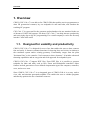
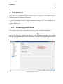
CNC-Calc v7 User Guide
CNC-Calc v7 User Guide
December 2013 | Copyright © 1991-2013 by CIMCO A/S | Email: [email protected]
1
CNC-Calc v7 User Guide
2
Table of Contents
License Information ........................................................................................................... 3
1.
2.
Overview ...................................................................................................................... 5
1.1.
Designed for usability and productivity ................................................................ 5
1.2.
User Interface ........................................................................................................ 6
Installation................................................................................................................... 7
2.1.
Enabling CNC-Calc .............................................................................................. 7
3.
Mouse Functions ......................................................................................................... 8
4.
CNC-Calc Tab ............................................................................................................ 9
4.1.
File......................................................................................................................... 9
4.2.
View .................................................................................................................... 10
4.3.
Modify ................................................................................................................. 11
4.4.
Snap ..................................................................................................................... 13
4.5.
Points and Lines .................................................................................................. 14
4.6.
Arcs and Circles .................................................................................................. 16
4.7.
Pattern ................................................................................................................. 18
4.8.
Text ..................................................................................................................... 19
4.9.
Milling Operations .............................................................................................. 20
4.10.
5.
Program Menu .......................................................................................................... 24
5.1.
6.
7.
Turning Operations .......................................................................................... 22
File Menu ............................................................................................................ 24
CNC-Calc Settings .................................................................................................... 25
6.1.
Main Configuration ............................................................................................. 25
6.2.
Color Configuration ............................................................................................ 27
Using CNC-Calc Help .............................................................................................. 28
7.1.
Using Help In Dialogs ......................................................................................... 28
7.2.
Printing Help Information ................................................................................... 29
License Information
3
License Information
Information in this document is subject to change without notice and does not represent a
commitment on the part of CIMCO A/S. The software described in this document may be
used or copied only in accordance with the terms of the license. The purchaser may make
one copy of the software for a backup, but no part of this user manual may be reproduced,
stored in a retrieval system, or transmitted in any form or by any means electronically or
mechanically, including photocopying and recording for any purpose other than the
purchaser's personal use, without prior written permission from CIMCO A/S.
TERMS OF USE FOR:
Software: CNC-Calc v7
Version: 7.x.x
Date: December 2013
Copyright © 1991-2013 by CIMCO A/S
Notice
CIMCO A/S reserves the right to make changes to the CNC-Calc v7 Software at any time
and without notice.
Software License
You have the right to use the number of licenses of the enclosed program, which you
have bought from CIMCO A/S. You may not distribute copies of the program or related
documentation to any persons or companies. You may not modify the program or related
documentation without the prior written consent of CIMCO A/S.
Disclaimer of all Warranties and Liability
CIMCO A/S makes no warranties, either express or implied, with respect to the software,
its quality, performance, merchantability, or fitness for any particular purpose. The entire
risk as to its quality and performance is with the buyer. Should the CNC-Calc v7 software
prove defective following its purchase, the buyer (and not CIMCO A/S, its distributor, or
its retailer) assumes the entire cost of all necessary servicing, repair, of correction and any
incidental or consequential damages. In no event will CIMCO A/S be liable for direct,
indirect, or consequential damages resulting from any defect in the software, even if
CIMCO A/S has been advised of the possibility of such damages. Some jurisdictions do
not allow the exclusion or limitation of implied warranties or liability for incidental or
consequential damages, so the above limitation or exclusion may not apply to you.
License Information
4
Notice:
The accompanying software is confidential and proprietary to CIMCO A/S. No use or
disclosure is permitted other than as expressly set forth by written license with CIMCO
A/S.
Copyright © 1991-2013 by CIMCO A/S. All rights reserved.
This software contains confidential information and trade secrets of CIMCO A/S. Use,
disclosure, or reproduction is prohibited without the prior express written permission of
CIMCO A/S.
CIMCO CNC-Calc, CIMCO Edit and the CIMCO Logo are trademarks of CIMCO A/S.
Microsoft, Windows, Win32 and Windows NT are registered trademarks of Microsoft
Corporation.
Other brand and product names are trademarks or registered trademarks of their
respective holders.
Overview
5
1. Overview
CIMCO CNC-Calc v7 is an add-on for CIMCO Edit that enables novice programmers to
draw 2D geometrical contours, lay out toolpaths for mill and lathe, and simulate the
resulting NC program.
CNC-Calc v7 is a great tool for the operators and toolmakers who are untrained in the use
of advanced CAD/CAM systems. For them, CNC-Calc v7 can help increase productivity
and assist in the day-to-day NC programming. For a small company it can be the first step
into the CAD/CAM world.
1.1. Designed for usability and productivity
CIMCO CNC-Calc v7 is designed for ease-of-use that enables the user to draw contours
fast and easily. It features common functions for drawing lines and circles in relation to
the coordinate system and/or existing geometry. Functionality ranges from the plain
"horizontal line" to the complex "circle tangent to three elements". It includes advanced
trimming capabilities and an easy point and click approach for toolpaths layout.
CIMCO CNC-Calc v7 imports DXF files. From DXF files it is possible to generate
toolpaths for lathe and mills, such as ISO, Fanuc and Heidenhain controllers. Other
features include generation of user-defined compensation types like computer, controller,
wear, and reverse wear.
Since CIMCO CNC-Calc v7 is an integrated part of CIMCO Edit it is an easy task to
view, edit, and simulate generated toolpaths. This enables the user to validate programs
and thereby optimize the use of machine resources.
Overview
6
1.2. User Interface
CNC-Calc v7 can draw 2D geometry, and generate NC code in ISO and Heidenhain
conversational format for contours and drilling cycles. The main program window (with
an empty drawing pane) looks like this:
CNC-Calc main window.
To the left of the drawing pane, you see the CNC-Calc and Element Info panes. The
CNC-Calc pane shows coordinate entry fields and other information about the activity
you are performing at any given time, while the Element Info pane shows the statistics of
any element hovered over by the mouse. Below an example of the Element Info pane
display is shown.
CNC-Calc pane with entry fields.
Element Info pane with information.
Installation
7
2. Installation
CNC-Calc v7 is installed as part of CIMCO Edit v7. Please see the CIMCO Edit v7
documentation for installation instructions.
If you are upgrading from an existing installation without CNC-Calc, reinstallation of
CIMCO Edit v7 is not necessary. Just copy the new key file (named "license.key") to the
appropriate directory.
2.1. Enabling CNC-Calc
Start CIMCO Edit v7 and verify that the CNC-Calc tab is available in the Ribbon.
If not, open the editor configuration by clicking the Global Setup icon in the Editor
tab. Go to the Plugins section in the left tree of the configuration window. Now ensure
that the option Disable CNC-Calc is unchecked. You must restart the program to activate
the CNC-Calc tab.
Enabling the CNC-Calc tab.
Mouse Functions
8
3. Mouse Functions
The mouse buttons are used to perform the following functions:
Left button
Selects whatever is described in the lower left corner of the program window.
Middle button (on most mice, pressing the scroll wheel)
Fits/zooms the geometry drawing to the entire graphics area. This can also be
achieved by clicking the
icon.
Right button
Drag the geometry drawing across the graphics area by holding down the right
mouse button as you drag the mouse.
Scroll wheel
Zoom in and out, centered on the cursor position.
CNC-Calc Tab
9
4. CNC-Calc Tab
In this section, the functions under the CNC-Calc tab are described.
The functions in CNC-Calc v7 are activated using the appropriate icons on the Ribbon.
The commands are organized into different menus under the CNC-Calc tab.
If the function can be activated through the Ribbon bar or a keyboard shortcut, the icon or
the shortcut is displayed next to the command name.
The CNC-Calc add-on is optional and will be present in the Editor only if you also
purchased it.
If the CNC-Calc tab is not available, please refer to Installation to read about how to
start CNC-Calc.
4.1. File
This section describes the functions in the File menu. These functions are used to handle
file operations like loading and saving files. You can also access the CNC-Calc
configuration through this menu.
The File menu.
New Drawing
Clears the graphics area and opens a new document.
Open Drawing
Opens existing CNC-Calc drawing files or DXF files.
The downwards arrow next to the Open Drawing icon gives access to a recent
files list, making it easy to reopen a file that you have been editing recently.
CNC-Calc Tab
10
Save
Saves the drawing to your hard disk. If it is the first time you save the drawing,
you will be prompted for a file location and name. Save function can also be
accessed with Ctrl+S.
Setup CNC-Calc
Lets you access the configuration for CNC-Calc.
Please refer to the section CNC-Calc Settings for more information on how to
configure CNC-Calc.
4.2. View
The functions in the View menu control the way the drawing is displayed in the graphics
area. Here it is possible to perform various zoom functions.
The View menu.
Zoom In
Zoom in centered on the middle of the graphics area. Zoom in can also be
accessed with Page Down.
Zoom out
Zoom out centered on the middle of the graphics area. Zoom out can also be
accessed with Page Up.
Zoom All
Use this function to fit the drawing to the graphics area. This can also be done by
clicking the middle button on the mouse (on most mice, pressing the scroll wheel),
or with Ctrl+End.
Zoom Window
Zoom Window lets you zoom in on an area, which you select by first clicking at
one corner, then dragging the rectangle and clicking at the opposite corner.
CNC-Calc Tab
11
4.3. Modify
This section describes the functions in the Modify menu. These functions are used to
modify the drawing geometry in different ways.
The Modify menu.
Trim To Intersection
Use this option to trim the selected element to the nearest intersection(s).
Select the element to be trimmed on that part to be removed. It is then trimmed to
the intersection(s) nearest to the point where it was selected. The trimmed element
is also broken in two if there are intersections on both sides of the selected point.
Trim One Element
Use this option to trim one element to another.
Select the element to be trimmed first, on the section to be kept, and then select
the element to trim to. This kind of trimming may extend the trimmed element to
the intersection with the element it is trimmed to.
Trim Two Elements
Use this option to trim two elements to each other.
Select the two elements to be trimmed, on the sections to be kept. This kind of
trimming may extend the trimmed elements to their intersection.
Fillet Elements
Use this option to create a fillet between two elements, with a fillet radius you
select.
It is optional whether the two elements should also be trimmed to the fillet.
Chamfer Elements
Use this option to create a chamfer between two elements, with a defined angle
and/or distance.
It is optional whether the two elements should also be trimmed to the chamfer.
CNC-Calc Tab
12
Break Element
Break element will divide an element into two pieces.
First select the element to be broken into two, and then select the point at which it
should be divided.
Join Elements
Use this option to join two selected elements into one.
Delete
Use this option to delete the elements you select. They can be restored with the
Undo function (the Undo icon in the Modify toolbar).
Remove Duplicates
Select this option to delete elements that are duplicated in the drawing.
Offset Elements
Use this option to offset the elements you select by a specified distance.
It is optional whether the original element should be kept.
Mirror Elements
Use this option to perform a mirror operation of the elements you select along a
line selected as the mirror axis.
It is optional whether the original element should be kept.
Translate Elements
Use this option to translate the elements you select along a vector defined by
selecting two points.
It is optional whether the original should be kept, and it is possible to create
multiple copies, where each copy is translated one step further along the selected
vector.
Rotate Elements
Use this option to rotate elements. This will create one or more copies of the
selected elements, rotated around a selected point, at a specified angle per copy.
It is optional whether the original element should be kept.
CNC-Calc Tab
13
Scale Elements
Use this option to create one or more copies of the selected elements, scaled about
a selected point by a specified scale factor.
It is optional whether the original element should be kept.
Undo
Select this option to undo one or more operations. This can mean deleting
elements created, restoring deleted elements, and/or undoing modifications to
elements. Undo can also be accessed with Ctrl+Backspace.
4.4. Snap
This section describes the different kinds of snap options that are available in the Snap
menu.
The snap option is only available when some point position has to be selected or
indicated.
The Snap menu.
Snap to Grid
Toggle snap to the grid points.
Snap to Points
Toggle snap to points drawn by the user.
Snap to Center Points
Toggle snap to the centers of circles and arcs.
Snap to Mid Points
Toggle snap to the midpoints of elements.
Snap to End Points
Toggle snap to the endpoints of elements.
CNC-Calc Tab
14
Snap to Intersections
Toggle snap to the intersections between elements.
Enable All Snap Types
Activates all snap types.
Disable All Snap Types
Deactivates all snap types.
4.5. Points and Lines
This section describes the functions in the Draw Points/Lines menu. This menu contains
functions for drawing points and lines defined in different ways.
The Draw Points/Lines menu.
Point
Use this option to draw a point at the selected position.
Between 2 Points
Use this option to draw a line between two selected points.
Vertical
Use this option to draw a vertical line.
The first point selected defines the starting point (and the X coordinate), the
second point selected defines the length (and need not be directly above or below
the first point).
Horizontal
Use this option to draw a horizontal line.
The first point selected defines the starting point (and the Y coordinate), the
second point selected defines the length (and need not be directly to the left or
right of the first point).
CNC-Calc Tab
15
Polar
Use this option to draw a line defined by its polar coordinates.
First select the starting point of a line, and you then select (or write) the angle and
length of the line.
Perpendicular
Use this option to draw a line perpendicular to another line.
You first select the line your new line is to be perpendicular to, then the starting
point of your new line. You then select the length of your new line, and last you
select in which direction from the starting point your new line is to go.
Parallel
Use this option to draw a line parallel to another line.
You first select the line your new line is to be parallel to, then the starting point of
your new line. You then select the length of your new line, and last you select in
which direction from the starting point your new line is to go.
Bisector
This option allows you to draw a line bisecting two other lines, i.e. a line that
halves the angle between two lines.
You first select the two lines you want to bisect, then you select the length of your
new line (from the intersection of the two lines you are bisecting), and last you
select which of the four possible solutions you want to keep.
Tangent Two Elements
Use this option to draw a line tangent to two circles or arcs.
You select the two circles or arcs your new line is to be tangent to, and then you
select which of the solutions you want to keep.
Tangent Angle
Use this option to draw a line tangent to an arc or circle, at a selected angle.
You first select the arc or circle your new line is to be tangent to, then the angle
and length, and last you select which of the two solutions you want to keep.
Tangent Through Point
This option lets you draw a line tangent to an arc or circle that goes through a
selected point.
You first select the arc or circle your new line is to be tangent to, then the point it
is to go through, and last you select which of the two solutions you want to keep.
CNC-Calc Tab
16
Rectangle
Use this option to draw a rectangle where you select the two opposite corners.
It is possible to define a corner radius for the rectangle (the corner radius is
ignored if there is not room for it).
4.6. Arcs and Circles
This section describes the functions in the Draw Arcs/Circles menu. These functions let
you draw full circles (360 degree arcs) and arcs defined in different ways.
The Draw Arcs/Circles menu.
Center Radius
This option lets you define the center of the circle, followed by the radius.
Two Points
Use this option to define the circle by selecting two (diametrically opposite)
points.
Three Points
Use this option to define the circle by selecting three points on the periphery of
the circle.
Tangent Two Elements
This option lets you define a circle tangent to two elements, of a defined radius.
You first write the radius, then you select the two elements the circle is to be
tangent to. Last you select which of the solutions you want to keep.
Tangent Center on Line
This option lets you define a circle tangent to one element, with its center on a
line, of a defined radius.
You first write the radius, then you select the line the center is to be on, and the
element the circle is to be tangent to. Last you select which of the solutions you
want to keep.
CNC-Calc Tab
17
Tangent through Point
This option lets you define a circle tangent to one element, through a point, of a
defined radius.
You first select the point the circle is to go through then write the radius, and
select the element the circle is to be tangent to. Last you select which of the
solutions you want to keep.
Tangent Three Elements
Use this option to define a circle tangent to three elements.
You select the three elements the circle is to be tangent to, and then you select
which of the solutions you want to keep.
Two Points
This option lets you draw an arc by selecting the endpoints of the arc, entering the
radius, and selecting which solution you want to keep.
Three Points
This option lets you draw an arc by selecting three points.
The arc created will not cross the zero degree point (3 o'clock). The
selection order of the three points is unimportant.
Start and End Angles
Use this option to define an arc by its center point, radius, starting angle, and end
angle.
Tangent Dynamic
Use this option to construct dynamic tangent from one element through a point.
CNC-Calc Tab
18
4.7. Pattern
This section describes the functions in the Pattern menu. These functions let you easily
create rectangular and circular bolt hole patterns.
The Patters menu.
Rectangular Bolt Hole Pattern
Use this option to define a rectangular bolt pattern.
You first select the start point of the pattern (one of the corners), and then enter
the step in X, step in Y, number of holes in X, number of holes in Y, and the hole
diameter.
Circular Bolt Hole Pattern
Use this option to define a circular bolt pattern.
You first select the center of the bolt pattern, select the radius of the bolt pattern,
and then enter the start angle, step angle, number of holes, and the hole diameter.
CNC-Calc Tab
19
4.8. Text
This section describes the functions in the Text menu.
These functions let you draw two kinds of letters: simple letters and TrueType letters. The
simple letters are like the letters used on drawings. These letters can be used to mill, for
instance, a part number on a part. The TrueType letter is more artistic, and any TrueType
font installed in the Windows operating system can be used.
The Text menu.
Text Entry
Use this option to define simple text written on a line.
You enter the starting point, angle of the line, then the distance between and
height of the letters. It is also possible to select the horizontal and vertical
alignment of the text.
Text Circular Entry
Use this option to define simple text that is written on a circle.
You select or enter the center and radius of the alignment circle, then the start
angle, space between and height of the letters. It is also possible to select the
horizontal and vertical alignment of the text on the circle.
TrueType Text Entry
Use this option to define TrueType text written on a line.
You enter the starting point and angle of the line, and then the height of the letters.
It is also possible to select the horizontal and vertical alignment of the text.
TrueType Text Circular Entry
Use this option to define TrueType text written on a circle.
You select or enter the center and radius of the alignment circle, then the start
angle and height of the letters. It is also possible to select the horizontal and
vertical alignment of the text, on the circle.
CNC-Calc Tab
20
4.9. Milling Operations
The functions in the Milling Operations menu allow the user to perform various
operations used in the manufacturing of parts. All the operations can be exported directly
to CIMCO Edit or to the clipboard, for insertion in a user-defined location.
The Milling Operations menu.
Face Milling
Use this option to create a facing operation based on a selected outline contour.
Pocket Milling
Use this option to create pocket operations for one or multiple pockets. These
pockets can contain multiple islands, or none.
In a single operation, it is possible to make both roughing and finishing cuts, but
only with one tool.
Contour Milling
Use this option to create operations for contour milling.
A contour operation can machine multiple contours with roughing and finishing
cuts, but only with one tool.
Drill Holes
Use this option to create drilling operations for hole drilling.
From a drawing, the hole positions can be selected with the use of a filter, or by
simply indicating the hole position. If multiple holes are drilled, they can be
arranged in both rectangular and circular patterns.
Helix Drilling
Use this option to generate operations for helix drilling.
Like normal drilling, multiple holes can be selected with the use of filters, or by
selecting the individual circles from the drawing.
Thread Milling
CNC-Calc Tab
21
Use this option to create threading milling operations. The threads can be inside or
outside, and can be created for tools with one or multiple teeth.
Multiple threads can be selected with the use of filters, or by selecting the
individual circles from the drawing.
Mill Letters
Use this option to generate operations for milling simple letters on the drawing.
These letters will have to be drawn using the simple letter function.
All letters can be selected with the window function, and machined in operations
based on their start and end depths.
Mill TrueType Letters
Use this option to create operations to mill the outline and/or the interior of the
individual letters. These letters will have to be drawn using the TrueType letter
function.
The letters can be selected with the window function, and all letters with the same
parameters can be machined in one operation.
Export Contour
This option can export a contour that the operator has selected on the drawing.
If a controller has smart canned cycles, for example a specific pocket operation,
the user can create a macro in the editor to support this, and then export the actual
contour for insertion in the canned cycle.
Calculator
Feed and speed calculator is used to generate tool changes, or to simply calculate
the feed and speed, based on the data of a specific tool.
CNC-Calc Tab
22
4.10. Turning Operations
The functions in the Turning Operations menu allow the user to perform various
operations used in the manufacturing of parts. All the operations can be exported directly
to CIMCO Edit or to the clipboard, for insertion in a user-defined location.
The Turning Operations menu.
Roughing Turning
Use this option to create a roughing operation based on a selected outline contour.
In this operation it is possible to create both roughing and semi-finishing cuts, but
only with one tool.
Face Turning
Use this option to create a facing operation.
This operation can contain both roughing and finishing cuts, but only with one
tool.
Finish Turning
Use this option to create a finish operation based on a selected contour.
This operation will make only one toolpath that fits the selected contour.
Grooving
Use this option to create a grooving operation based on a selected contour.
This will enable machining of the areas that could not be machined with either the
Roughing or Finishing operation.
End Drilling
This option generates operations for drilling a center hole in the part.
The drilling operation will be performed as one continuous motion or as pecking
with or without dwelling at the end of each plunge.
CNC-Calc Tab
23
Threading Horizontal
Use this option to create threading operations for inside and outside threads.
The geometry of the thread can be entered by hand or selected from tables. The
thread geometry can be normal or conical.
Cutoff
This option generates an operation for cutting off the part from the stock.
In the operation it is possible to define the corner geometry as sharp, round or
chamfered.
Export Contour
This option can export a contour that the operator has selected on the drawing.
If a controller has smart canned cycles for example a specific roughing operation,
the user can create a macro in the editor to support this, and then export the actual
contour for insertion in the canned cycle.
Calculator
The feed and speed calculator is used to generate tool changes, or to simply
calculate the feed and speed, based on the data for a specific tool.
Program Menu
24
5. Program Menu
Most of the CNC-Calc v7 functions are accessed through the menus in the CNC-Calc tab.
However, a few are logically located under the global
File menu.
5.1. File Menu
Close
Closes the active file. If the active file has been modified, you will be prompted to
save it. Close can also be accessed with Ctrl+F4.
Close All
Closes all open files. If any files have been modified, you will be prompted to
save them.
Save
Saves the drawing to your hard disk. If it is the first time you save the drawing,
you will be prompted for file location and name. Save can also be accessed with
Ctrl+S.
Save As
Saves the drawing under a different name.
Exit
Closes CIMCO Edit v7, and thus also CNC-Calc v7. If any files have been
modified, you will be prompted to save them. Exit can also be accessed with
Alt+F4 (Alt+F4 is a Windows standard).
The functions New and Open under the File menu respectively create an empty NC
document and open an NC file from disk respectively. To create or open CNC-Calc
drawings use the functions New Drawing and Open Drawing located in the File toolbar.
CNC-Calc Settings
25
6. CNC-Calc Settings
This section describes in details the configuration of CNC-Calc.
Perhaps the most important thing to remember when configuring CNC-Calc is that the
configuration is specific to each machine type.
6.1. Main Configuration
The main configuration is entered most easily by selecting the icon
from the File menu.
Setup CNC-Calc
Opening the CNC-Calc setup window.
It is important to select first the correct machine type under the File types setup dialog,
since all settings will apply for the selected machine. The window below shows the main
configuration dialog.
Main CNC-Calc configuration window.
CNC-Calc Settings
26
The top part of the CNC-Calc configuration dialog contains the settings for toolpath
output, with the settings for the drawing grid at the bottom section.
CNC-Calc Settings
Turning
Check this option to select turning (lathe) output.
Diameter programming
Selects whether X axis output is in diameter measurement or in radius
measurement. This option is only available if turning (lathe) output is selected.
Selected Post Processor
Use this field to specify the post processor that should be used to format the output
of the CNC-Calc operations. Click the folder icon
at the right of the field to
browse for the desired post processor.
If changes need to be made to a post processor to suit your personal needs, feel free
to contact CIMCO A/S at [email protected] or at telephone +45 4585 6050.
Grid
Show grid
Use this check box to specify if the grid should be shown.
Grid size
Use this field to set the spacing between main grid points.
Show sub-grid
Select this option to have a sub-grid visible when zoomed in to a degree that shows
few main grid points.
Show origin
Select this option to have lines along X and Y zero visible.
CNC-Calc Settings
27
6.2. Color Configuration
The Color configuration is entered by selecting Global Colors in the configuration tree,
and scrolling down to the CNC-Calc colors in the list.
CNC-Calc color configuration window.
To change the color of a CNC-Calc element, either left click the element in the list to
select it and then click the Select Color button, or you can double-click the element in the
list. The color can then be picked from a standard palette, or a custom color can be
defined.
To quickly modify a specific color, select it from the list and move the sliders to get the
desired color.
Using CNC-Calc Help
28
7. Using CNC-Calc Help
This section describes how to use the help system in CIMCO products.
A standard Windows Help file is available through the drop-down Help menu by clicking
CNC-Calc help.
Help menu.
7.1. Using Help In Dialogs
CIMCO CNC-Calc v7 contains multiple dialogs that provide drop-down lists, check
boxes, text fields and buttons for specific configurations.
To get help for a particular dialog item, click the ? at the top of a dialog box, as shown
below.
Click the question mark.
This will change the cursor to an arrow and a question mark indicating that you are in
Help Mode. The new pointer is shown below.
The question cursor.
Now click on the item that you want further information about. If help is available for the
selected item, a small window will pop up displaying the help text. If no help is available
the general help file is launched. An example of a pop-up help is shown below.
Using CNC-Calc Help
29
The pop-up information.
You can also display the pop-up help for a dialog item by clicking in the field and then
pressing F1.
7.2. Printing Help Information
If you wish to print just a single section of this help file, click the Print button on the
toolbar (shown below).
Help buttons.
If you wish to print more than a few sections, you should open the PDF version of the
help file. The PDF document produces a much nicer printout.
You can download the PDF version of the user guide from the CIMCO website.
You will need Adobe Reader to open the PDF file.