1
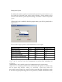
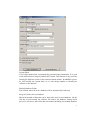
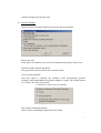
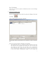
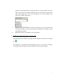
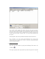
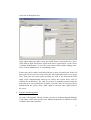
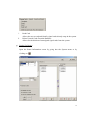
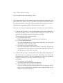
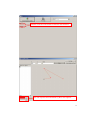
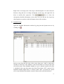
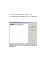
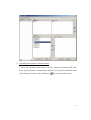
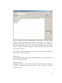
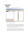
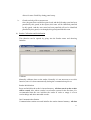
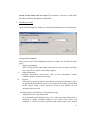
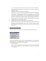
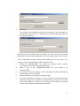
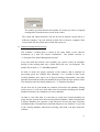
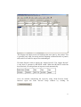
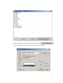
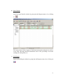
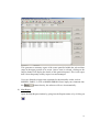
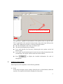
Advanced Patrol Management System
Version 7.x
Guard Tour Management Software
User’s Manual
Table of Contents
I. INTRODUCTION
1
II. SYSTEM REQUIREMENTS
1
III. SOFTWARE INSTALLATION
1
IV. HARDWARE QUICK START GUIDE
2
V. INSTALLING SIGNAL CARD CHECKPOINTS
2
VI. STARTING UP THE SOFTWARE
2
VII. USING THE SOFTWARE
4
VIII. MAINTENANCE FUNCTIONS
20
IX. PATROLLING
26
X. VIEWING REPORTS
26
XI. METHODS OF DATA OUTPUT
31
I.
Introduction
Patrol Management System guard tour management software is an integral part of an
electronic guard tour system, which is composed of this software, guard tour readers,
and RFID checkpoints. It is designed for the acquisition, evaluation and reporting of
guard tour data. It works by installing a series of signal cards (also called inductive
cards or information buttons, each with its own unique identification number) along
patrol routes, and having patrolling personnel perform readings on the cards they
pass using hand held readers. The recorded cards numbers and associated
time-stamps are later uploaded via communication stations to computers for
processing and verification. The results are displayed on the screen, where managers
are able to review the job performance data of the patrolling personnel (attendance,
locations patrolled, timeliness, incidences, etc).
Advanced Patrol Management System has the following main features:
•
Three password levels permit control of access to the software.
•
Reports can be saved to file as PDF file, Excel file, CSV file, or send the reports
in an email.
•
Allow producing individualized client-based reports from some of the reports.
•
Provides the history database. Users could inquiry the history reports by
switching the database.
•
Importing of graphic images and inquiring the map report.
•
Customizing the Basic Report.
II.
System Requirements
a) Operating system requirement: Windows 2000, Windows XP, Windows 2003 or
Windows Vista.
b) Minimum hardware requirement: 1.5GHz CPU, 512MB RAM, 50 GB Hard
Drive, CD Rom Drive, USB port.
c) Important: The screen resolution should be set to 1024*768
III.
Software Installation
a) Execute the program “setup.exe”.
b) During the setup process, the software will automatically install the database
used by the system and prompt the user to install the USB driver used by the
communication stations that work with the guard tour readers. If the hardware
can not be found by computer, please install the BC-USB driver provided on the
software installation CD or by your dealer.
1
c)
If you have data from a version 5.x software installed on the system that you
would like to transfer into the version 7.x software, please use the database
upgrade utility provided on your software installation CD or by your dealer.
d)
If you have data from a version 6.x software installed on the system that you
would like to transfer into the version 7.x software, please use the import and
the export function to transfer data from 6.x into 7x and then reprocess the
data.
IV.
Hardware Quick Start Guide
a) Using Reader Model BP-2002S, BP-2002F
Move the reading head of the reader (the larger end) toward the signal card. Card
reading will be automatically performed (for more details on the usage of the
BP-2002S, BP-2002F reader, please refer to the manuals that accompany them).
The reader will beep once and flash its red LED indicator light three times to
indicate a proper reading.
b) Using Reader Models BP-2002-W, BP-2002B-W
Briefly pressing the button on the reader will turn it on. Holding it down for 1-2
seconds will cause it to read a signal card. The signal card needs to be 1-5
centimeters in front of the guard tour reader’s blue reading head. On models with
LCD displays, the reader will immediately display the last four digits of the
RFID card number.
For more details on the usage of the guard tour readers, please refer to the
manuals that accompany them.
V.
Installing Signal Card Checkpoints
Checkpoints are represented by RFID cards, each with its own 10-digit hexadecimal
globally unique identification code. They are usually installed either on or beneath
wall surfaces. Sub-surface installations are generally recommended, because it helps
to prevent damage and sabotage. They can be installed up to 2cm beneath wall
surfaces. The recommended installation height from the ground is 1.4m, or whatever
height from which the guards can comfortably perform readings.
VI.
Starting Up the Software
After installation, you will able to start the program by going into:
Start-> Program Files ->Advanced Patrol Management System -> Advanced Patrol
2
Management System
By default, the software requires a username and password to operate. However, you
can disable the Password Login option in the software’s System Settings screen
(from its main menu: System->System Settings) to disable a multi-level operator
system.
If Password Login is enabled, when the program starts, you will be greeted with a
logon screen.
There are three logon operators each with different levels of rights:
Operator Name:
“User”
“Administrator” “Super User”
Initial Password:
(blank)
1111
1234
Allows Data Input:
Yes
Yes
Yes
Allows System Setup:
No
Yes
Yes
Allows Reader Initialization:
No
No
Yes
Allows Import of Basic Data
No
No
Yes
-“User” can be used by lower-level management to perform data uploading and
verifications.
-“Administrator” can be used by upper-level management to alter system setups.
-“Super User” is completely without limits, and it allows the operator to perform tasks
such as import data, initialize readers, etc. Initializing a guard tour reader will
irrecoverably erase all data it has stored. For this reason, other than initializing a reader
for first time using and performing data recovery functions, standard administrative tasks
3
should be performs by logging on as Administrator. The software logs in as Super User
automatically if the Password Login function is disabled.
Higher level operators are able to reset the passwords of lower level operators. Selecting
“Change Password After Logon” will allow you to change the password of the current
operator, and clear the password of the lower level users to their original state. Changing
operator passwords is highly recommended as a security precaution.
Upon first time using, login as Super User and go through the initial steps to setup your
patrol management system (see below for instructions on working with each part of the
process). Later when it is not necessary to initialize guard tour readers, system
administrative tasks can be performed by logging on as Administrator.
VII.
Using the Software
a) System Settings
Open the System Settings window by going into the System menu.
4
System Label
A five-digit number that is automatically generated upon installation. It is used
in the data records to uniquely identify this system. This function is only used for
identify the different system in the network-related utilities. WARNING: please
do NOT modify the system label, as it is the unique number to identify the
software on the Internet.
Backup Database Folder
The location where the active database will be automatically backed up.
Keep in Current (Active) Database
Shows the months of data that can be kept in the actively used database. On the
first day of each month, the software will archive the database, during which
process it will move data older than last month (including last month) database
5
from the active database to a history database, please find out the history
database from the folder “PatrolArchiveData”.
In order to maintain optimal performance of the software, the active database
will never contain data from more than the selected number of months. Data
from previous months can be viewed by using the Switch Database function
from the System menu.
Archive Database Folder
The location where archived history databases are stored.
Company Code
Similar in nature to System Label, and is used by network-related utilities.
Company Name
Allows for the customization of the name of the company using the system.
System Name
Allows for the customization of the name of the software system, which is
displayed in the background of its main interface screen.
Title
Displayed above System Name, can be changed by the user.
Subtitle
Displayed below System Name, can be changed by the user.
Automatically Process Data
Let the system automatically process data uploaded from the readers. It can be
deselected if the user’s computer system is slow and therefore does not wish to
wait for the data to process after every upload. In this case, data can be processed
by using the Reprocess function in the main menu or the Process Data function
in the Reader Communication screen.
Route Has No Order
All new routes that are setup would be defaulted as having no order once this
box is checked.
Password Login
If this option is unchecked, the system will automatically login as Super User
6
without prompting for the password.
b) Function Settings
Open the System Settings window by going into the System menu.
Password Login
If this option is unchecked, the system will automatically login as Super User.
Guard Card Only Affects One Route
The guard card read only affects the route that follows.
Auto Generate Schedule
Once this option is checked, the software would automatically generate
schedules when unscheduled checkpoint readings are made. The default options
are “Guard’ and “First Checkpoint”.
Conditions of Auto Generate Schedule
Show Route Scheduling Options
Allows for the scheduling of patrols based on routes.
7
Show Client Manager
Allows the users to have an option on whether they want to use the “Manage
Clients” feature.
c) Setting Up Checkpoints Cards
Open the checkpoint information window by going to the Manage Cards menu
or clicking
Click on Add Checkpoint to enter the “add mode”
Input the name and the location that this card is installed (e.g. Office, Front door,
etc)
There are several ways that the card number can be inputted:
i.
After installing the cards, use a guard tour reader and read the cards in the
order that they will be patrolled, while taking note of the exact time that
each reading was made. Then, place the reader on the communication
station connected to the computer, and click “Connect” on the main screen
to go into the Reader Communication window. The new signal card
8
numbers will automatically be registered into the “Unused Cards” list. Now
when you go into the checkpoint window, the new cards will be listed in the
order with which they were read. Selecting one of the numbers will
associate it with the input entry.
ii.
iii.
Mark on each signal card the location at which they will be installed, then
read them directly into the system during checkpoint card setup via the
communication station.
Manually enter the card numbers via the keyboard.
d) Setting Up Guard Cards (Setup-> Guard Cards)
Open the guard card window by going into the Manage Cards menu or clicking
on
This function is optional but recommended because it is necessary to identify
each guard when checking on their performance from the patrol reports.
9
Press “Add” to add a guard to the software, then place the patrol personnel’s
signal card between the LED lights of the communication station to be read by
the system. The card ID can also be manually entered using the keyboard or be
selected from the list under “Unused Cards” if it was previously uploaded into
the system.
Enter the guard’s name, and any additional comments and select his/her sex.
Press “Confirm” to save the current guard information. You can then enter
information for the next guard. Press “Cancel” to undo the current modifications
and stop adding new guards.
e) Setting Up Event Cards
Enter the event cards window by going into the Manage Cards menu or by
clicking on
This setup is optional, and is only needed if you wish to keep track of events that
10
can occur at checkpoint sites.
In the upper-right part of the screen, press Add Event to enter names for events.
(This must be done first before signal cards can be registered for events.) Press
“Confirm Modification” to save the event entered and continue adding more.
Press “Cancel Modification” to stop adding events.
Each event can be each be associated with one or more of signal cards. In the left
part of the screen, select an event, and on the lower-right part of the screen, press
Add. Then place the event signal card that you wish to use between the LED
lights of the communication station to be read by the system. Press “OK” to
confirm the modification. The card ID can also be manually entered using the
keyboard or be selected from the list under “Unused Cards” if it was previously
uploaded into the system. Press “Add” again to associate more signal cards to
the event.
f)
Signal Card Management
All cards (Checkpoints, Guards, Events) can also be managed through Manage
Cards menu, which also provides two additional functions in addition to those
available on the main interface:
11
i.
ii.
Read Card
Allows the user to read and identify signal cards already setup in the system.
Delete Unused Cards From the Database
Allows for the deletion of unassigned signal cards from the system.
g) Setting Up Routes
Open the Route Information screen by going into the System menu or by
clicking on
12
Press “Add” to add a new route.
Type in a name for the route, and press “OK”.
The Length value specifies the amount of time allowed for the completion of the
patrol route. (If its value is set to “0”, then the system will not expect the route to
be completed within a certain time. This means that until the next route starts, or
when the data is uploaded to the PC, the last route never “ends”.)
There are several ways in which the properties of a patrol route can be modified:
i.
If “Route Has No Order” is checked (the default for this can be modified in
the System Settings screen), it means that the checkpoints on this route do
not need to be patrolled in the order which they are listed.
The sub-options for this condition include:
a) No Checkpoint Has Order
All the checkpoints can be patrolled in any order designed.
b) First Checkpoint Has Order
The first checkpoint on the route must be read first, the rest of the
checkpoints can be read in any order.
c) First and Last Checkpoints Have Order
The first checkpoint on the route must be read first, and the last
checkpoint on the route must be read last. Other than these, the rest of
the checkpoints can be read in any order.
ii. If “Route Has No Order” is unchecked, it means that all the checkpoints on
this route need to be patrolled in the order which they were setup. The
Checkpoint Error value is the error allowed for each of the checkpoint
readings in which they can still be counted as being on time.
Sub-options:
a) Free Intervals for Checkpoints
This allows a free interval between checkpoints.
b) Checkpoints Have the Same Intervals and Errors
If this is checked, the time intervals between the checkpoints will be
equal, and is automatically calculated (route length divided by the
number of checkpoints minus 1).
13
c) Manually Setup Intervals & Error Time
If this is unchecked, the Checkpoint Error setting below Length will be
hidden, and a Time tab will appear on the right side of the screen,
allowing the user to separately designate the interval and error values
for each individual checkpoint.
Does Not Check For Early Or Late Patrols
If this is checked, checkpoint cards read within their error range will be
counted as “On-Time”, and those unread or read outside of their error range
will be counted as “Missed”.
If this is unchecked, checkpoint card read outside of their error range, but
still within the time length of the route will be counted either as “Early” or
“Late”, depending on the situation. (Note: due to the nature of the patrol
routes, the first checkpoint of the route is not able detect “Early” readings,
and the last checkpoint is not able to detect “Late” readings.)
“Map” (optional) will allow the user to graphically plot out each patrol route.
Click the
icon in “Map” window to select the main background
picture. The preferred picture dimension is 640*480 pixels. It could only insert
the pictures in .jpg or .bmp format.
Alternatively, you may double click the route name to enter the sub-window.
(See the picture below).
14
Double click the route name to enter the sub-window.
The line layout can be modified by these two options
15
Right click on an empty area of the map to add checkpoints. Use the left mouse
button to drag and move existing checkpoints on the map, and right-click on
them to modify their properties. Click
icon to show the
checkpoints detailed information on the map. User can edit the line layout by
choosing the two options on the left bottom corner of the window.
h) Schedule Setup
Open the Schedule Information window by going into the System menu or by
clicking on
Select a route from the left side of the screen, then press “Add” to add patrol
schedule to that route. The schedule’s start and end times are setup on the right
side of the screen. If the Schedule Number is set as 1, then the system will create
1 schedule for the route that starts at the Start Time when “OK” is pressed. If a
Schedule Number higher than 1 is chosen, when “OK” is pressed, the system
will evenly distribute that number of patrols between the start and end times.
16
Checking Work Days (i.e. Mon to Sun) will allow the user to modify the days of
the week to perform the patrol. Press “OK” to save any modifications.
i)
Manage Clients (optional)
Open the Manage Clients window by going into the System menu.
If you are managing multiple clients using the software, you can use this feature
to assign different checkpoints and routes to different clients. This allows you to
produce individualized client-based reports from some of the reports.
The Clients tab allows you to enter, modify, or delete information on your clients.
The Client’s Routes tab allows for the association of specific routes and
checkpoints to different clients, which can be used as filter conditions when
generating reports.
17
j)
Uploading Data (Reader Communication)
Connect the communication station to the PC using the included USB cable.
Then open the Reader Communication window by going into the Reader menu
and clicking on Connect or by clicking the
icon on the main screen.
18
Once the System finds the communication station, place the reader inside
(reader’s antenna head between the station’s LED lights). The system will
automatically find the reader, calibrate its time using the PC’s time, upload its
data, and automatically process the data (if the Automatically Process Data
option is turned on in System Settings). Close the window when there are no
more readers to upload.
If a reader is connected to the system for the first time, a window will prompt the
user to enter a name for the reader.
Process Data
Manually starts data processing if the Automatically Process Data option was not
turned on in System Settings.
Re-Read Records
Uploads data that has already been uploaded. Select the number of records to
re-upload ( counting back from the newest record), and press “Re-Read
Records” to start.
19
VIII.
Maintenance Functions
a) Reader Setup
Open the Reader Setup window by going into the Reader menu.
This performs the following functions:
i.
Modify assigned names for the readers.
ii.
Associate a guard with a specific reader. This way, all checkpoint readings
done by the reader will be recorded as having been performed by this guard.
This effect is the same as reading a guard card before starting patrol routes,
but override guard card readings. This is an optional setting, and should only
be used when the reader is used only by one guard.
iii.
Associate routes with a specific reader. This is important especially when
the same checkpoint is used by more than one route. When a reader records
a checkpoint associated with multiple routes, the system will always assume
that the checkpoint belongs to the route associated with this reader. This
20
allows for more flexibility during patrol setup.
iv.
Guard card only affect current route
Once the guard has read his/her guard card, and the following route has been
patrolled by this guard, in the reports, this route will be identified patrolled
by this guard. And the next route has been patrolled will not be identified
patrolled by this guard, even thought, this guard patrolled this route.
b) Reader Calibration and Initialization
This function can be opened by going into the Reader menu and choosing
Initialize.
Calibrate
Manually calibrates time on the reader. Normally it is not necessary to use this
function, since it is done automatically during the communication process.
Reader Initialization
Reset and initialize the reader’s internal memory. All data stored on the reader
will be erased. Also, when a reader is used on the system for the first time, it is
recommended that the user initialize the reader in order to empty it of test
card-readings and other unneeded records.
Init Communication Station
Communication station reset and initialize the station internal memory. All data
21
stored on the station will be erased. This function is effective on BS-2000,
BS-3000, BS-4000, BS-4000m and BS-6000.
c) Data Reprocessing
Open the Data Reprocess window by clicking on Data Reprocess from the menu.
Background Information
Data stored in the Patrol Management System software are divided into three
types:
i.
Signal card readings
These include the ID of the signal cards read as well as the time when they
were read. This is what is seen in Basic Report.
ii.
Setup information
Includes information entered that relate to how checkpoints, routes,
schedules, guards, and events are setup.
iii.
Reports
Generated by analyzing signal card readings using setup information. These
are generated automatically whenever new signal card readings are uploaded
to the system using a direct connection (remote data uploads are not
automatically processed).
The following are the functions of Data Reprocessing:
i.
Alignment of new setup information
In an installed system that has been in use, when any setup information is
modified or added, including adding of new signal cards, routes, and
schedules, it will be necessary to perform data reprocessing so new reports
22
ii.
iii.
can be generated properly based on the newly entered setup information.
When performing this function, it is normally not necessary to modify the
default date range.
Integration of data received from other channels
When the system receives signal card reading data from remote connections
(for example, over mobile phone networks using BS-3000, or over standard
telephone lines using BS-4000), it is necessary to perform data reprocessing
to generate reports based on this new data. It should also be performed if
guard tour data has been imported using the Export and Import menu item.
The time interval for the reports that need to be generated can be selected
using the Start Date and End Date menus.
Modification of past reports based on new setup information
If it becomes necessary to modify past reports based on newly entered setup
information, Data Reprocessing can be used. The time interval for the
reports that need to be modified can be selected using the Start Date and End
Date menus.
d) Exporting and Importing Data
These functions can be accessed by going into the Export and Import menu.
These are functions that can be used to create data backups, or to transfer the
working data set of one installed system to another. There are two main types of
data on which these operations can be performed.
i.
Basic Information
This is the setup information of the patrol routes, such as checkpoints,
guards, routes, schedules, etc. This information is exported and saved with
“.txt” extension.
23
ii.
Raw Data
The original card reading data uploaded by the readers. This information is
exported and saved with “.rec” extension. Raw Data of different periods can
be exported separately.
After these data are imported into the software, the user will need to perform
Data Reprocess before patrol information for the relevant periods can be viewed.
i.
ii.
iii.
iv.
v.
If the working data becomes damaged and unusable, the user can restore it by
using previously exported data by following these steps:
Delete the “BA2004.ABS” file under the program folder (usually
“C:\Program Files\Patrol Management System”).
Make a copy of the “EmptyBA2004.ABS” file, and rename it as
“BA2004.ABS”.
Go into the “Export and Import” menu, and import the Basic Information
and Raw data previous exported.
Perform data reprocess on the relevant date range.
If recent patrol data are missing, you can re-upload it from the guard tour
readers by going into the Reader Communication screen (go the Reader
menu and clicking on Connect or by clicking on the button on the main
screen.) and using the Re-Read Records function.
24
The number specified indicates the number of records you wish to re-upload,
counting back from the newest record in the reader.
The export and import functions can also be used to transfer system data to a
different computer. Copy the backed up data files to the new computer, then
restore them into the system and perform data reprocess.
e) Database Backup and Archiving
The software’s working data is stored in the same folder as the software
installation in a data file named “ba2004.abs”. The default location is:
“C:\Program Files\Patrol Management System”
Every time that the software exits normally, the system creates an automatic
backup of the working data into a folder which the user can designate. The
default file location is: “C:\PatrolBackupData\”
In order to ensure the proper operation of the software and to maintain its
processing speed, the software only maintains 2 to 3 months of data in the
working database (this can be set in System Settings). Meanwhile, data older
than the last month (including last month) has been archived in the archive folder.
The default location for history databases is: “C:\PatrolArchiveData\”
On the first day of each month, the software will archive the database, during
which process it will move data older than last month (including last month)
database from the active database to a history database
In order to view older data, it is necessary to switch into a history database by
going into the System menu and selecting Switch Database. When switched into
a History Database, the operator is only allowed to browse the data. Functions
including Reader Communication and Data Reprocess are disabled. To go back
to the working database when done browsing older data, exit then restart the
software.
25
IX.
Patrolling
These are the steps that a patrol personnel should follow in order to complete a patrol
shift:
a) If a Guard Card is setup for the patrol personnel, read it first. Subsequently, all
signal cards read will be associated with this particular personnel until another
Guard Card is read. Make sure that the guard cards are not read in the middle of
patrol routes, which can cause the data to become unrecognizable by the
software.
b) Read the starting checkpoint of the route. This will identify the route and the
shift to the system. All subsequent checkpoints read will be associated with this
route, until a new starting checkpoint is read.
c) Go to the checkpoints and read the signal cards installed, in the order that they
were setup. If events occur at a checkpoint, read the associated events cards
(carried by the guards) after the checkpoint’s signal card is read.
d) After patrols are done, either the patrol personnel or a manager can perform the
data upload. (Click “Connect” on the main screen, then connect and turn on the
reader) The operator “User” should be used to perform this task. The software
will automatically perform reader communication, time calibration, data
upload/download, data processing, and shift/route verification. Be sure to wait
until the software confirms that the data has been processed before exiting the
screen or performing other tasks.
X.
Viewing Reports
a) Basic Report
Open the Basic Report window by going into the Reports menu or by clicking on
26
This displays the unprocessed card readings that were done by the readers. This
is generally only used for tracing and investigating unfiltered details of patrols,
and can be less useful for supervisors and managers.
The Basic Report is able to display the “Impact Record”. The “Impact Record”
is only able to generate by BP-2002F reader. When the BP-2002F reader has
been shocked, it would generate an impact records automatically.
Users are allowed customizing the report by using “Print Preview Setup’
function. Open the Print Preview Setup window by clicking on
27
Users could check on the specific options to display on the Basic Report. If you
want to make any further modifications please click
on the Print Preview Setup window go to the Print Setup window.
28
b) Patrol Details
Open the Patrol Details window by going into the Reports menu or by clicking
on
This report allows for the inquiry of individual checkpoints and guard as well as
event cards. Showing detailed information such as the percentage of on-time
readings for checkpoints, etc.
c) Shift Report
Open the Shift Report window by going into the Reports menu or by clicking on
29
This generates a summary report of the routes patrolled within the selected date
range in the upper portion of its screen. Once a route is selected, clicking on the
Inquiry button will display the details of this particular patrol. This is the report
that is most frequently used by supervisors and managers.
Users are allowed to input some comments for the unusually results, such as
MISSED, EARLY, LATE or ORDER ERROR. Please input your comments into
the
column directly, the software will save it automatically.
d) Map Report
Open the Map Report window by going into the Reports menu or by clicking on
30
The missed checkpoint keeps flashing
This generates a graphical representation of the patrols done on specific date.
This is applicable if the operator had previously setup route maps during route
setup. In this Map Report window, it has the following features.
l The first checkpoint of the route is in black color.
l The missed checkpoint keeps flashing.
l User could edit the line layout by choosing the two options on the left
bottom corner.
l User could view the detailed patrol results for each of the checkpoints on the
selected map. The report is shown on the left of the window.
l
Press
to display the detailed information for each of
checkpoints.
XI.
Methods of Data Output
Patrol reports can be outputted via the following methods:
a) Print
Each setup and report screen contain a Print Preview or Print button, which the
operator can output the information displayed to the printer.
31
b) Email
In most Print Preview screens, pressing this button
will allow the operator to
email the information displayed to a designated recipient.
c) Adobe PDF
In most Print Preview screens, pressing this button
will allow the operator to
export the information displayed to Adobe PDF format.
d) Microsoft Excel
In most Print Preview screens, pressing this button
then selection “Excel
table” will allow the operator to export the information displayed to Microsoft
Excel format. Alternatively, some of the report interfaces have buttons labeled
“Export to Excel” which can perform this function directly.
32