1
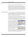
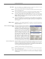
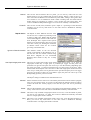
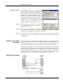
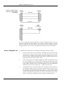
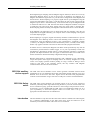
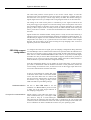
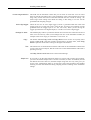
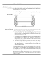
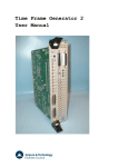
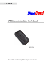
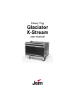
22
Auxiliary states devices
When sampling using multiple frame states, Signal can control external devices such as
stimulators in addition to switching the 1401 outputs. This is achieved by using auxiliary
states devices; external equipment that is set up in different ways according to the
sampling state.
Signal auxiliary states device support provides a mechanism for controlling arbitrary
equipment and setting it up in different ways according to the sampling state in use. In
addition to controlling equipment settings by state, Signal is also able to provide devicespecific configuration dialogs, to check the equipment health and readiness while
sampling, to save the stimulation parameters used in the new data file and to save and
load auxiliary states setup information to and from sampling configurations. Script
language functions (SampleAuxStateParam and SampleAuxStateValue) are also
provided to give access to the auxiliary device settings.
Signal currently supports two types of auxiliary states device; the Magstim range of
transcranial magnetic stimulators and the CED 3304 programmable constant current
stimulator. You can select which of these devices you wish to use (or none) during the
Signal installation process, if you wish to change the type of auxiliary states device in use
the simplest way to do this is to re-install Signal. If you need auxiliary states device
support for other equipment please contact CED.
Magstim auxiliary The Magstim range of transcranial magnetic stimulators are widely used to provide nondevice support invasive neuronal and muscular stimulation. Signal provides support all three types of
Magstim (the 200, BiStim and Rapid), as the software uses a serial line for control of the
stimulator only the modern Magstims that provide serial line control (these have a 2
suffix to the model name) can be used. In addition Signal can also control a pair of
Magstim 2002 units using two serial lines.
Magstim Safety notice Transcranial magnetic stimulators are dangerous devices capable of causing serious harm
and should only be used by qualified medical practitioners. Before using a Magstim
device you should read the user’s manual produced by Magstim paying particular
attention to the warnings and precautions section. It is your responsibility to ensure that
Signal’s control of a Magstim is set up in an appropriate and safe fashion for the intended
use and to verify that it is operating correctly. CED is not responsible in any way for
problems caused by use of this software.
introduction For Magstim devices, the auxiliary states system sets the power output and (where
appropriate) inter-pulse timing, remote control of the hardware can be disabled for
specific states to allow the user to control the stimulation manually. Options are provided
to cause Signal to assume independent triggering mode and to enable high resolution
interval timing (for the BiStim2) and to cause the Magstim to ignore the coil interlock
switch and to enable single pulse mode (for the Rapid2). This documentation only
describes the controls available from within Signal; for a complete understanding of the
effect these have upon the behaviour of the stimulator you should consult the Magstim
user manuals.
In addition to using a serial-line to set the stimulation parameters, standard operation
with Signal requires that the stimulation be triggered using one or more TTL pulses
generated by the 1401 digital outputs. This allows the pulse timing to be precisely
controlled relative to the Signal sampling. A Rapid2 can be configured to either generate
a train of pulses in response to a single trigger or to generate one pulse per trigger,
allowing complete control of the patterns of stimulation. Manual triggering of the
22-1
Signal for Windows version 4
stimulator is also possible, as is triggering from other external hardware, in which case
you would use the Magstim trigger to trigger the sampling sweep as well.
The Magstim support monitors the stimulator health; both waiting until the Magstim is
ready for use before allowing a sampling sweep to proceed and terminating sampling if a
hardware problem develops. To aid data analysis, Signal saves the Magstim stimulation
parameters used in the data section variables of the sampled file. The parameters saved
are the power level, the pulse interval (BiStim only), the secondary power level (BiStim2
and dual 2002), the pulse frequency (Rapid2 only) and the pulse count (Rapid2 only).
These values are placed in the first user frame variables in the sampled data file. The
saved values can be retrieved using the script language; later versions of Signal may
make use of them directly.
Magstim configuration To configure a Magstim in Signal, open the sampling configuration dialog and make sure
that Multiple states is enabled in the General tab. Select the States tab and make sure that
you are in Dynamic outputs or Static outputs mode. If Magstim support is installed, there
will be a button labelled Magstim. If this button is not present, reinstall Signal and make
sure that you select Magstim auxiliary states device support. If the button is present, but
disabled, you are in External Digital states mode, change the mode to enable the button.
Click the button to open the Magstim configuration dialog.
It is meaningful to use the Magstim support without using multiple states, but this is not
directly supported because the states system is so closely linked to the Magstim support.
If you want to make use of Magstim support without using multiple states (so that the
pulse parameters are recorded and Magstim health checks are made, but with complete
manual control) you should turn on multiple states, set only one extra state, set state zero
to use manual control, and only make use of state zero while sampling. This will allow
you access to the Magstim configuration dialog to set the basic Magstim parameters.
At the top of the configuration dialog there is a
selector used to select the Magstim type. You
should set this to the type of stimulator you
will be using or to Do not use if you do not
want to make use of the Magstim support in
this sampling configuration. If you set the
device type incorrectly this will not always be
detected, though errors during sampling will
almost certainly result. Below the device
selection is a selector for the COM port used to
control the stimulator, you can select any port
from COM1 to COM9. As many PCs only
have one COM port you may have to use a
USB serial port expander to provide a spare
COM port – we have found that most of these
USB serial ports work satisfactorily.
Below the basic stimulator configuration there are controls that vary according to the
type of stimulator selected. These are in three sections; first there are controls which
govern the overall behaviour for all states, next is a display of settings for all states which
is used to select a state for editing (by clicking on the information for that state) and
finally an area where the settings for the selected state may be edited.
22-2
Auxiliary states devices
2002 device
This is the simplest type of Magstim and does not require any controls for overall
behaviour. The settings available for the individual states are:
Manual
Set this checkbox for this state to be controlled by the manual controls and not by Signal,
clear it to give Signal control.
Power
This sets the stimulator power output as a percentage of the maximum available, you can
set any value from 0 to 100. This control is disabled for manually controlled states.
Copy...
The buttons labelled Copy to all and Copy above can be used to set up many states
quickly; Copy to all copies the currently selected state to all other states, while Copy
above copies the current state’s settings to all higher state numbers. These buttons are
available for all types of Magstim.
Test
The button labelled Test tests if communications with the Magstim can be established. It
checks that you have the correct COM port, that the serial line is connected and that the
Magstim is communicating correctly with Signal. These buttons are available for all
types of Magstim.
BiStim2 device
The BiStim2 is more complex than the 2002, in essence it is two 2002 units with one
slaved to the other. When a BiStim2 device is selected two controls governing overall
behaviour are shown:
BiStim in independent trigger
mode
Use Hi-res timing mode
This sets how Signal will expect the BiStim2 to
be configured, rather than how it will be set up
by Signal. Normally, a BiStim2 generates two
output pulses, one at the time of the trigger and
the second at a preset interval after the trigger.
Using the controls on the front of the BiStim2
master unit, you can set the device into
independent trigger mode (referred to as IBT
mode in the Magstim documentation). When
this mode is in use two separate triggers are
used (presumably signals from two 1401
digital outputs), one trigger firing the main
pulse and the other firing the second (Power B)
pulse. Because a BiStim2 behaves rather
differently when in IBT mode it is important
that you set this checkbox correctly to match
the BiStim setup you will be using otherwise
errors will be generated when you try to sample.
When this checkbox is clear, the interval between the two pulses can be set to any value
between 0 and 999 milliseconds, the actual timing in the BiStim2 will be set with a
resolution of 1 millisecond. With this checkbox set, the maximum interval is reduced to
99.9 milliseconds but the interval timing resolution is improved to 0.1 milliseconds. This
control is disabled if independent trigger mode is selected.
The BiStim2 settings available for the individual states are:
Manual
Set this checkbox for this state to be controlled by the manual controls and not by Signal,
clear it to give Signal control.
Power
This sets the main (master) stimulator power output as a percentage of the maximum
available, you can set any value from 0 to 100. This control is disabled for manually
controlled states.
22-3
Signal for Windows version 4
Interval
This sets the interval between the two pulses, you can use any value from 0 to 999
milliseconds (or 0 to 99.9 milliseconds for Hi-res timing). Setting a value of zero for a
state will switch the BiStim2 into simultaneous pulse mode, setting a value greater than
zero switches it out of simultaneous mode. While switching back and forth between
modes during an experiment is possible, it may increase the inter-sweep delay. This
control is disabled if independent triggers are in use or for manually controlled states.
Power B
This sets the second (slave) stimulator power output as a percentage of the maximum
available, you can set any value from 0 to 100. This control is disabled for manually
controlled states.
Rapid2 device
The Rapid2 is rather different from the other
two devices as it is capable of producing a train
of pulses at high rates. Rather than the simple
case-mounted manual controls of the other two
units, the Rapid2 has a separate control system
that has to be disconnected to gain access to the
serial line control port, limiting the usefulness
of manual control. There are two controls
governing overall behaviour:
Ignore coil interlock switch
This disables checks on the coil interlock
switch on the handle of the Magstim coil, so
that the unit will fire without a button being
held down. Magstim do not recommend
disabling these checks as they are a safety
feature.
Use Rapid single-pulse mode
This turns on single-pulse mode, which allows higher power levels - up to 110%. In
single-pulse mode only a single pulse is produced per trigger and the pulse train
parameters are ignored. The pulse rate can be up to 100 Hz normally (depending upon
the power level used – see the user manual) but if you select power levels above 100%,
the maximum allowed pulse rate is forced to 0.5 Hz. With single pulse mode turned off a
train of up to 1000 pulses can be generated at the specified frequency from one trigger
and power levels above 100% are not available. Again, the pulse rate can be up to 100
Hz depending upon the power level used.
The Rapid2 settings available for the individual states are:
22-4
Manual
Set this checkbox for this state to be controlled by the manual controls and not by Signal,
clear it to give Signal control. As you have to disconnect the manual controls in order to
connect the serial line used by Signal, I fear that this option will not be particularly
useful.
Power
This sets the stimulator power output as a percentage of the maximum available, you can
set any value from 0 to 100. This control is disabled for manually controlled states.
Pulses
This item is only available if single-pulse mode is not in use, it sets the number of pulses,
you can set any value from 1 to 1000. This control is disabled for manually controlled
states or if single-pulse mode is selected.
Freq
This item is only available single-pulse mode is not in use, it sets the pulse frequency in
Hertz, you can set any value from 0 to 100. This control is disabled for manually
controlled states or if single-pulse mode is selected.
Auxiliary states devices
Dual 2002 devices
Two Magstim 2002s can be controlled by
Signal to achieve much the same effect as
using a BiStim2, when using this configuration
two separate serial lines are used to control the
Magstims and two separate trigger pulses are
required (as for a BiStim in independent trigger
mode). When the dual 2002 option is selected a
separate selector for the second serial-line port
is shown but as for the 2002 there are no
controls governing overall behaviour. The
settings available for the individual states are:
Manual
Set this checkbox for this state to be controlled
by the manual controls and not by Signal, clear
it to give Signal control.
Power
This control sets the main (master) stimulator
power output as a percentage of the maximum available, you can set any value from 0 to
100. This control is disabled for manually controlled states.
Power 2
This control sets the second stimulator power output as a percentage of the maximum
available, you can set any value from 0 to 100. This control is disabled for manually
controlled states.
Magstim Connections There are two connector arrangements provided by Magstim for serial line control and
and cabling external triggering of the unit. Older 200 and BiStim units have an arrangement with a 9way serial line and separate 15-way trigger connector while newer 200 and BiStim units
and all Rapids have a high-density 26-way combined serial line and trigger connector.
In both cases two separate connections need to be made; serial line control from a PC and
a TTL trigger signal from the 1401. The standard high level trigger input suggested by
Magstim works well with Signal and the 1401 and is used in the diagrams shown below,
consult the Magstim documentation if you require a different arrangement. In the case of
a Rapid stimulator, the 26-way connector is also used by the integrated control system
and this will need to be disconnected before the control cable can be connected.
Cabling for 26-way combined
serial and trigger connector:
22-5
Signal for Windows version 4
Cables for separate 9 pin
serial and 15-way trigger
connectors:
If you are not using the external trigger input to trigger the Magstim from the 1401 you
will need a different cabling arrangement, for example to take the Magstim low-going
trigger out signal (on pin 8 of the 26-way connector) and use that as an input to the 1401
to trigger the 1401 sweep. Consult your Magstim documentation for more information.
Notes on Magstim use
22-6
A straightforward arrangement to use a Magstim with Signal would be as follows:
1.
Connect the serial port of your computer to the Magstim serial line input using
the appropriate serial line cable. Connect the trigger BNC plug to the 1401
digital output port 0 BNC socket found on the front of all modern types of 1401.
If you are using a 1401plus the digital output pulse is available from the 25-way
digital output socket on the front of the 1401.
2.
In the outputs page of the sampling configuration, make sure that digital output
bit zero is enabled for use. Using the pulses configuration dialog set the initial
level of digital output bit zero to 0 and place a pulse (which will be high-going)
in the outputs at the time when you want the Magstim to fire. This output pulse
should be at least 10 microseconds long – 1 millisecond works well.
3.
The Magstim support uses Signal multiple states sampling, which should be set
up in dynamic outputs mode. You can use any number of extra states, each extra
state providing separate Magstim settings. Each set of pulse outputs should
include digital output pulses to trigger the Magstim along with any other outputs
required. The Magstim support will work correctly with manual control of the
states or with any style of automatic states sequencing including protocols.
Auxiliary states devices
When Signal begins sampling with the Magstim support enabled, it checks for a correctly
functioning Magstim device as part of the process of initialising for sampling. If a
Magstim is found then Signal will carry out the initial configuration of the Magstim and
arm the device. While sampling is in progress, Signal will set up the Magstim using the
current state data before each sweep, it will then delay the start of each sweep until the
Magstim reports that it is armed and ready. At the end of each sweep the Magstim health
is checked to make sure it is OK. Note that the checks on Magstim readiness can impose
a significant extra inter-sweep delay though steps have been taken to minimise this.
When sampling finishes normally, the Magstim is disarmed and remote control disabled.
If the Magstim coil temperature rises too high, Signal will stop sampling. Once the coil
temperature has dropped sufficiently you can press ‘More’ on the sampling control panel
to resume sampling again.
While sampling is in progress, Signal continuously maintains communications to prevent
the Magstim from disabling remote control and disarming itself. If Signal ceases to
communicate with the Magstim because it has encountered a significant problem
(“crashes”), the Magstim will disarm itself automatically within 1 second, but this safety
feature only applies if manual control has not been selected by Signal beforehand.
If manual control is selected, the Magstim will disarm itself spontaneously only after 60
seconds have passed without a stimulus trigger, so it is your responsibility to make sure
the Magstim is disarmed if manual control is used and Signal encounters a significant
problem. The Rapid stimulator does not appear to disarm itself after 60 seconds in this
manner and must be disarmed manually if Signal fails during sampling.
Because Signal needs to communicate frequently with a Magstim to stop it disarming,
scripts that operate while Signal is sampling need to be correctly designed. If a script
carries out a lengthy operation without yielding or using a toolbar or dialog to allow
control to pass back to the operating system, this may interfere with Magstim
communications and cause the unit to disarm.
CED 3304 auxiliary The CED 3304 current stimulator can be used to generate controlled constant-current
device support stimulations of up to 10 milliamps and is fully controlled by Signal, allowing you to set a
different level of current for each state. Signal controls the CED 3304 programmable
constant current stimulator using a serial line or USB port to interact with the hardware.
CED 3304 Safety The CED 3304 current stimulator can generate outputs of up to 90 volts, which lies
notice within the potentially lethal range. Before using the device you must read the CED 3304
Owners Handbook paying particular attention to the warnings and precautions section.
In particular, you are reminded that the CED 3304 is not qualified for human use. It is
your responsibility to ensure that Signal’s control of a CED 3304 is set up in an
appropriate and safe fashion for the intended use.
Introduction This documentation only describes the CED 3304 controls available from within Signal;
for a complete understanding of the effect these have upon the behaviour of the
stimulator you should consult the CED 3304 Owners Handbook.
22-7
Signal for Windows version 4
The CED 3304 produces current pulses in one of four current ranges: 10 and 100
microamps and 1 and 10 milliamps. The current range is selected by a manual switch on
the CED 3304. You specify a current range when you define the stimulus settings in
Signal; Signal will not let you sample if the wrong range has been set on the CED 3304.
The timing of the 3304 current pulses is controlled by a TTL signal connected to the
front panel Trigger input. Signal can control the timing of the current pulses with one of
the 1401 digital outputs in Dynamic outputs mode, or external equipment can control the
pulsing in Static outputs mode. For safety reasons, the CED 3304 will switch off a pulse
after a preset limit is reached – see the 3304 documentation for details of how to control
this limit.
Signal monitors the stimulator health; waiting until it is ready for use before allowing a
sampling sweep to proceed and terminating sampling if a hardware problem develops. To
aid data analysis, Signal saves the stimulation current in the data section variables of the
sampled file. This value, in uA, is placed in the first user frame variable in the sampled
data file. The saved values can be retrieved using the script language; later versions of
Signal may make use of them directly.
CED 3304 support To configure the CED 3304 in Signal, open the sampling configuration dialog and make
configuration sure that Multiple states is enabled in the General tab. Open the States tab and make sure
that you are in Dynamic outputs or Static outputs mode. If CED 3304 support is present,
there will be a button labelled CED 3304. If this button is not present, reinstall Signal
and make sure that you select CED 3304 stimulator support. If the button is present, but
disabled, you are in External Digital states mode. Change the mode to enable the button.
Click the button to open the CED 3304 configuration dialog.
From the configuration dialog you can enable use of the CED 3304, set the serial line
port used to communicate with the hardware and other overall parameters, define the
current settings for each state in use, set the active level for the Trigger input and test for
successful communications with the CED 3304.
At the top of the dialog are settings that apply
to all states. In the centre is a list of the currents
set for each state. Below this is a field to edit
the current for the selected state. At the bottom
are buttons to copy settings, get help, test the
CED 3304 and accept the dialog settings.
Hardware selection
Com port for communications
22-8
Set this to Use CED 3304 to use the
stimulator or to Do not use if you do not want
to make use of the 3304 support software in
this sampling configuration.
Signal connects to the CED 3304 either via a
serial communication port, or through a USB
port, which is setup as a virtual COM port.
This field sets the COM port that the CED 3304 is connected to. If you use the USB
connection, follow the instructions at the start of the Operation chapter of the CED 3304
Owners Handbook to obtain a suitable device driver for your operating system.
Auxiliary states devices
Current range selection
This field sets the maximum current that you can enter for each state. You can select
from 10 and 100 microamps and 1 and 10 milliamps. This control matches the current
range rotary switch on the front of the CED 3304 but does not override its setting – the
actual range switch setting must match the setting in this dialog or an error will be
generated when sampling is begun.
Active high trigger
Check the box for an active high trigger (current is generated while the CED 3304
Trigger input is at a high TTL level). Clear the box for active low operation (current
generated when the Trigger input is at a low TTL level). When you are driving the
trigger input from the 1401 digital outputs, it is usual to set an active high trigger.
Settings for state...
This field displays and lets you edit the desired current for the state selected in the list of
states. You can enter any value (in microamps) from zero to the maximum available, for
example in the 10 uA range you could enter: 0 or 8.234 or 10.
Copy...
The buttons labelled Copy to All and Copy above can be used to set up many states
quickly; Copy to All copies the currently selected state to all other states, while Copy
Above copies the current state’s settings to all higher state numbers.
Test
This button tests if communications with the CED 3304 can be established. It checks that
you have the correct COM port, that the serial line is connected and that the CED 3304 is
operating correctly.
The Help, Cancel and OK buttons have their usual meanings.
Simple use
If you want to use the CED 3304 from Signal very simply with a single current setting,
you must still enable multiple states. Set one extra state (so states are enabled), and set
the desired current for state zero, and then sample using state zero only. This gives you
access to the configuration dialog to set the basic CED 3304 parameters and enables
checking of CED 3304 behaviour during sampling and the recording of the stimulation
settings.
22-9
Signal for Windows version 4
CED 3304 Connections The CED 3304 uses a USB A-B cable or a 9-pin serial-line cable (both are supplied with
and cabling the unit) for control. Use one cable or the other. If you plug in both, the USB connection
will take precedence. See the Operation chapter of the CED 3304 Owners Handbook for
more information about the control cables.
The front panel Trigger input should be connected to the 1401 digital outputs or other
TTL pulse source using a standard BNC cable. The front panel Data and Clock inputs
are not used with Signal and should be left unconnected.
3304 serial cable
Notes on 3304 use
A straightforward arrangement to use a CED 3304 with Signal, assuming we use digital
output bit 0 to control the current pulse timing, would be as follows:
1.
Connect your computer to the CED 3304 using the either a serial or use a USB
connection. Connect the CED 3304 front panel Trigger BNC plug to the 1401
digital output 0 BNC socket found on the front of all modern types of 1401. If you
are using a 1401plus the digital output pulse is available from the 25-way digital
output socket on the front of the 1401.
2.
In the Outputs page of the sampling configuration, make sure that digital output bit
zero is enabled for use. Using the pulses configuration dialog, set the initial level of
digital output bit zero to 0 and place a pulse (which will be high-going) in the
outputs at the time when you want the CED 3304 to fire. This output pulse should be
as long as the required stimulation.
3.
The CED 3304 support is designed to work with Signal multiple states sampling,
which should be set up in Dynamic outputs mode. Set one extra state for each output
current setting you require and each state should generate digital output pulses to
trigger the CED 3304 plus any other outputs required. The CED 3304 support will
work with manual control of the states or with any style of automatic states
sequencing including protocols.
When Signal begins sampling with the CED 3304 support enabled it checks for a
correctly functioning device. If a CED 3304 is found, Signal will check the range switch
setting, initialize the device and enable the trigger. While sampling is in progress, Signal
sets the output current using the state data before each sweep. At the start and end of
each sweep the CED 3304 health is checked to make sure it is OK. When sampling
finishes, the CED 3304 trigger is disabled.
Because of the extra overhead in setting up current levels for each sweep and checking
that the device is operating correctly, you may find that the maximum sweep rate with the
CED 3304 is reduced.
22-10