1
NetMediator RTD G5
USER MANUAL
Visit our website at www.dpstelecom.com for the latest PDF manual and FAQs.
July 15, 2015
D-UM-NM832-12012
Firmware Version 5.3H
Revision History
July 15, 2015
Display Mapping Update
November 29, 2011
Updated TTY Interface images
July 30, 2011
Initial Release
This document contains proprietary information which is protected by copyright. All rights are reserved. No part of this
document may be photocopied without prior written consent of DPS Telecom.
All software and manuals are copyrighted by DPS Telecom. Said software and manuals may not be reproduced, copied,
transmitted or used to make a derivative work, by either mechanical, electronic or any other means in whole or in part, without
prior written consent from DPS Telecom, except as required by United States copyright laws.
2015
Notice
The material in this manual is for information purposes and is subject to change without notice. DPS Telecom shall not be
liable for errors contained herein or consequential damages in connection with the furnishing, performance, or use of this
manual.
Contents
Visit our w ebsite at w w w .dpstelecom .com for the latest PDF m anual and FAQs
1 NetMediator RTD G5 Overview
1
1.1 About This Manual
1
1.2 Specifications
2
1.3 Shipping List
3
1.4 Optional Accessories
4
2 Hardware Installation
6
2.1 Tools Needed
6
2.2 Mounting
6
2.3 Power Connection
7
2.4 LAN Connection
8
2.5 Telco Connection
8
2.6 Alarm and Control Relay Connections
9
2.6.1
Grouped Alarms and Derived Controls
2.6.2
Alarm and Control Relay Connector Pinout Table
11
2.6.3
Discretes 1–24 Connector Pinout Diagram
12
2.6.4
Analogs1–6/Discretes 25–32/Relays 1–8 Connector Pinout Diagram
13
2.6.5
Analog Dipswitches
14
2.6.6
Integrated Temperature and Battery Sensor (Optional)
15
2.6.6.1
Analog Step Sizes
9
15
2.7 Data Ports
16
2.7.1
Port Allocation
17
2.7.2
Connecting NetMediator RTD DX Expansions
17
2.7.3
GLD/ECU Expansion Port (RS-485)
18
2.8 Optional Hinged Wire-Wrap Back Panel
2.8.1
Lexan Wire-Wrap Cover
2.9 Control Relays
2.9.1
Control Relay Jumper Settings
3 LCD Display
19
20
21
22
3.1 Alarm and Control Status Messages
3.1.1
18
LCD Point Mode Operation
3.2 LCD Command Menu
22
23
23
3.2.1
Sound off
24
3.2.2
Reboot
24
3.2.3
Run Config
24
3.2.4
Contrast
25
4 Alarm Speaker
25
5 Front Panel LEDs
26
6 Back Panel LEDs
27
7 Initial Configuration
28
7.1 ... via Craft Port
28
7.2 ... via LAN
30
7.3 Ethernet Port Setup
31
8 Advanced TTY Configuration
32
8.1 Restoring Default Derived Logic
33
8.2 Ethernet Backup Mode
33
8.3 Edit PPP Port
34
8.4 RADIUS Configuration
35
8.5 TTY Command Mode
36
9 Monitoring the NetMediator via the TTY Interface
40
9.1 Base Alarm Status
41
9.2 Ping Targets
41
9.2.1
Viewing Live Ping Targets
42
9.3 Operating Relays (Controls)
42
9.4 Monitoring Analogs
43
9.5 Monitoring System Alarms
43
9.6 Monitoring Data Port Activity
44
9.6.1
Proxy Menu
44
9.7 Monitoring the Accumulation Timer
45
9.8 Event Logging
46
9.9 Debug Input and Filter Options
47
10 Backing Up NetMediator Configuration Data via FTP
10.1 Reloading NetMediator Configuration Data
11 Reference Section
11.1 Display Mapping
48
48
49
49
11.1.1 NetMediator RTD DX Expansion 1
50
11.1.2 NetMediator RTD DX Expansion 2
51
11.1.3 System Alarms Display Map
52
11.2 SNMP Manager Functions
55
11.3 SNMP Granular Trap Packets
56
11.4 Trap SNMP Logic
57
11.5 ASCII Conversion
57
11.6 RADIUS Disctionary File (Available on Resource Disk)
58
12 Frequently Asked Questions
59
12.1 General FAQs
59
12.2 SNMP FAQs
62
12.3 Pager FAQs
63
13 Technical Support
64
14 End User License Agreement
65
1
1 NetMediator RTD G5 Overview
The NetMediator RTD G5 has the tools you need to manage your remote site.
The NetMediator RTD G5 - The Intelligent RTU for Complete Site Management
The NetMediator RTD G5 is a RoHS 5/6-compliant, LAN-based, SNMP/DCPx remote telemetry unit. The
NetMediator RTD G5 has all the tools you need to manage your remote sites, including built-in alarm monitoring,
paging and email capabilities that can eliminate the need for an alarm master.
Increased Analog Visibility & Grouping
Your NetMediator RTD G5 is preset with control logic to provide an automated relay response to preset groups of
discrete, system, and analog threshold alarms. It supports up to 2 RTD 32 DX expansion units, for up to 72 total
analog inputs, maximizing temperature monitoring coverage. Analog channels on the RTD 32 DX Expansion units
are also covered by your NetMediator's base control logic.
Redundant NetMediators Ensure Monitoring Never Fails
Your NetMediator RTD G5 is designed to work in tandem with another NetMediator RTD G5 to provide
redundant monitoring and control responses. Configure primary and secondary NetMediators to ensure that you
never lose coverage at your site.
With the NetMediator, you can:
Monitor 32 discrete alarms, 32 ping alarms, and 8 analog alarms
Expand analog coverage to 72 sensors with RTD 32 DX units
Control remote site equipment via 8 terminal server ports and 8 control relays
Set threshold groups and derive relay actions based on analog threshold alarms
Monitor your remote site from anywhere using the NetMediator's built-in Web Browser Interface.
Report alarms to multiple SNMP managers or the T/Mon Alarm Monitoring System.
Report alarms via LAN or dial-up connection.
Automatically send pager and email alarm notifications 24/7.
Connect multiple concurrent users via Telnet over LAN to telecom switches, servers, radios, PBXs and
other equipment.
Ping IP network devices and verify that they're online and operating.
Configure redundant LAN connectivity, to ensure reporting even if the primary LAN path fails
1.1 About This Manual
There are two separate user manuals for the NetMediator RTD G5: the Hardware Manual (which you're reading
now), and the NetMediator RTD G5 Web Interface User Manual.
This Hardware Manual provides instructions for hardware installation and use of the TTY interface. The Web
Interface User Manual provides instructions for databasing the NetMediator's alarms, analogs, control relays, and
other system information via the unit's web interface.
See the Grouped Analogs and Derived Controls section of this manual for more information about your
NetMediator's derived relay logic and alarm groups.
2
1.2 Specifications
Discrete Alarm Inputs:
Analog Alarms:
Analog Input Range:
Analog Accuracy:
Control Relays:
Maximum Voltage:
Maximum Current:
Ping Alarms:
Protocols:
Interfaces:
Max Dimensions:
Weight:
Mounting:
Power Input
Voltage Options Include:
`
Current Draw:
GMT Fuse:
Modem:
Visual Interface:
Audible Notification:
Operating Temperature:
Operating Humidity:
*RoHS 5 Approved
32
8 (Expandable to 72 with DX Expansions)
(–94 to 94 VDC or 4 to 20 mA)
+/- 1% of Analog Range (See Analog Step Sizes)
8 Form C
60 VDC/120 VAC
1 Amp, AC/DC
32
SNMPv1, SNMPv2c, SNMPv3, DCPx, DCPf, TRIP, SNPP
SMTP, TAP, HTTP, FTP, TELNET, ICMP, RADIUS
9 RJ45 Yost serial ports
2 RJ45 10/100 Ethernet ports
1 RJ11 telco jack
2 50-pin amphenol connectors (discretes, controls, and analogs)
1 4-pin screw connector (analogs)
1.75"H x 17"W x 8.136"D (12.75"D with back panel)
(4.5 cm x 43.2 cm x 20.6) (32.4 cm with back panel)
4 lbs. 3 oz. (1.9 kg)
19" or 23" rack
–48 VDC nominal (–36 to –72 VDC)
–24 VDC nominal (–18 to –36 VDC)
Wide Range –24/–48 VDC ( –18 to –72 VDC)
+24VDC (+18 to +36VDC)
200 mA at 48 VDC
3/4 amp recommended
33.6 K internal
LCD display
16 bicolor LEDs
5 unicolor LEDs
Alarm speaker
32°–140° F (0°–60° C)
0%–95% noncondensing
Note: This equipment has been tested and found to comply with the limits for a Class A digital device, pursuant to
part 15 of the FCC Rules. These limits are designed to provide reasonable protection against harmful interference
when the equipment is operated in a commercial environment. This equipment generates, uses, and can radiate
radio frequency energy and, if not installed and used in accordance with the instruction manual, may cause
harmful interference to radio communications. Operation of this equipment in a residential area is likely to cause
harmful interference in which case the user will be required to correct the interference at his own expense.
3
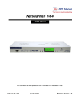
1.3 Shipping List
While unpacking the NetMediator RTD G5, please make sure that all of the following items are included. If some
parts are missing, or if you ever need to order new parts, please refer to the part numbers listed and call DPS
Telecom at (800) 622-3314.
NetMediator RTD G5
D-PK-NM832-12012
NetMediator RTD G5 Hardware
Manual D-UM-NM832-12012
NetMediator RTD G5 Resource CD
(includes manuals, MIBs, and software)
DB9M-DB9F Download Cable 6 ft.
D-PR-045-10-A-04
Two Ethernet Cables 14 ft.
D-PR-923-10A-14
Telephone Cable 6 ft.
D-PR-045-10A-01
23" Rack Ears
D-CS-325-10A-01
19" Rack Ears
D-CS-325-10A-00
Eight 3/8" Ear Screws
1-000-60375-05
Four Standard Rack Screws
1-000-12500-06
Four Metric Rack Screws
2-000-80750-03
Two 3/4-Amp GMT Main Power Fuses
2-741-00750-00
Two Large Power Connector Plugs for Main Power
2-820-00862-02
Four Cable Ties
(Sixteen with hinged panel)
4
4 Pin Analog Connector
2-820-00814-02
Pads
2-015-00030-00
Screws and connectors are packaged in a sealed hardware kit, shown above
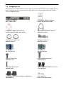
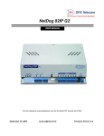
1.4 Optional Accessories
You can extend the capabilities of the NetMediator RTD G5 through accessory units that provide greater discrete
alarm capacity, remote audiovisual alarm notification, visual surveillance of remote sites, and other options. If you
would like to order any of these accessories, or if you would like more information about them, call DPS Telecom
at (800) 622-3314.
RTD 32 DX Expansion
D-PK-DXRTD-12001.00001
The RTD 32 DX provides an additional 32 analog inputs for your NetMediator RTD G5. You can attach up to 2
RTD DX units to your NetMediator RTD G5 for a total analog capacity of 72 inputs. Scaling, threshold, and
alarm groups are all configured from the primary NetMediator RTD G5 unit, keeping all of your analog inputs on
one interface for simplified configuration.
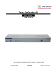
General LCD Display (GLD)
D-PC-820-10A-04
The General LCD Display (GLD) is a small wall-mounted remote terminal for the NetMediator RTD G5. The
LCD display shows system status and alarm messages, and the built-in speaker gives an audible notice of alarms.
Up to 12 GLDs can be daisy-chained off the NetMediator RTD G5.
5
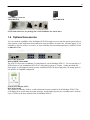
SiteMon IP G2
D-PK-CAMRA
The SiteMON provides streaming video security surveillance of remote sites and provides an additional 2 discrete
inputs, 2 analog inputs, and 2 control relays. You can set the SiteMON to record images on a trigger. You can
also monitor your SiteMON's view in real-time through the NetMediator's Web Browser Interface.
Hinged Wire-Wrap Back Panel
For 19" rack: D-PK-NGPAN-12002
For 23" rack: D-PK-NGPAN-12006
The hinged wire-wrap back panel provides wire-wrap connections for the NetMediator's alarms and control
relays.
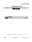
NetGuardian 3288 Test Fixture
D-PK-TSTBX-12005.00001
Every DPS product is rigorously tested before shipping, and the NetGuardian Test Box allows technicians to
verify every discrete alarm input, control relay, and voltage-based analog alarm input on a NetMediator RTD G5.
This time-tested tool is now available to you as the NetGuardian 3288 Test Fixture (known casually as the
"NetGuardian Test Box"). With 32 discrete alarm toggles, 8 analog knobs, and 8 control relay LEDs, you can
verify every alarm input and control output on your NetMediators in a controlled way.
6
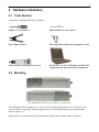
2 Hardware Installation
2.1 Tools Needed
To install the NetMediator RTD G5, you will need:
Phillips No. 2 Screwdriver
Small Standard No. 2 Screwdriver
Wire Strippers/Cutter
Wire Wrap Gun (if hinged wire wrap panel is used)
Punch Down Tool (if 66 blocks are used)
PC with access to the NetMediator (for initial TTY
configuration and subsequent Web configuration)
2.2 Mounting
The NetMediator RTD G5 can be flush or rear-mounted
The NetMediator RTD G5 mounts in a 19" rack or a 23" rack using the provided rack ears for each size. Two
rack ear locations are provided. Attach the appropriate rack ears in the flush-mount or rear-mount locations
shown in Figure 6.2.1.
Note: Rack ears can be rotated 90° for wall mounting or 180º for other mounting options (not shown).
7
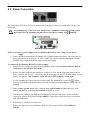
2.3 Power Connection
Power connectors and fuse.
The NetMediator RTD G5 has two screw terminal barrier plug power connectors, located on the left side of the
back panel.
The Grounding Lug on the back of the unit provides a permanent connection to earth ground
when connected. The Grounding Lug must be used in order to comply with
standards.
WARNING!
Grounding Lug and Symbol
Before you connect a power supply to the NetMediator RTD G5, test the voltage of your power
supply:
Connect the black common lead of a voltmeter to the ground terminal of the battery, and connect the red
lead of the voltmeter to the battery's –48 VDC terminal. The voltmeter should read between –43 and –
53 VDC. If the reading is outside this range, test the power supply.
To connect the NetMediator RTD G5 to a power supply:
1. Remove the fuse from the back panel of the NetMediator RTD G5. Do not reinsert the fuse until all
connections to the unit have been made.
2. Remove the power connector plug from Power Connector A. Note that the plug can be inserted into the
power connector only one way - this ensures that the barrier plug can only be reinserted with the correct
polarity. Note that the –48V terminal is on the left and the GND terminal is on the right.
3. Use the grounding lug to connect the unit to earth ground. The grounding lug is next to the
symbol.
Insert the eyelet of the earth ground cable between the two bolts on the grounding lug (Ground cable not
included).
4. Insert a battery ground into the power connector plug's right terminal and tighten the screw; then
insert a –48 VDC line to the plug's left terminal and tighten its screw.
5. Push the power connector plug firmly back into the power connector. If the power feed is connected
correctly, the LED by the connector will light GREEN. If the polarity of the power feed is reversed, the
LED will not illuminate.
6. Repeat Steps 2–4 for Power Connector B.
7. Reinsert the fuse to power the NetMediator RTD G5. The front panel LEDs will flash RED and
GREEN.
8
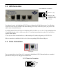
2.4 LAN Connection
RJ45 Ethernet Connection
8
7
6
5
4
3
2
1
Receive In – (RI–)
Receive In + (RI+)
Transmit Out – (TO–)
Transmit Out + (TO+)
Ethernet port pinout
Two 10/100 Ethernet ports
For enhanced security, the NetMediator RTD G5 has two independent 10/100 Ethernet ports. You will assign
each port its own separate IP address and subnet allowing you to safely connect one port to your private LAN
and the other to the public Internet.
By default, outbound data traffic from the NetMediator RTD G5 will be sent over Net 2. Only outbound data that
is specifically directed to Net 1, will be sent to Net 1. To use both network interfaces, place Net1 and Net2 on
separate Subnet Masks.
To use only one of the network interfaces, set the unused port IP, subnet, and gateway to 255.255.255.0.
When a connection is established on Net1 or Net2, the corresponding LED will turn solid green.
2.5 Telco Connection
Telco jack
The rear panel telco jack (see Figure 6.5.1) connects the NetMediator RTD G5 internal modem to a standard
phone line for dial-up access and pager alarm notification.
RJ11 Phone Line Connection
4
3 Ring
2 Tip
1
Telco jack pinout
9
2.6 Alarm and Control Relay Connections
Alarm and control relay connectors
You'll connect dry contacts, analog sensors, and control relays to the NetMediator's two 50-pin connectors labeled
"Discretes 1–24" and "Analogs 1–6/Discretes 25–32/Relays 1–8" on the back panel. Analog alarm inputs 7 and 8
are connected through the four-pin connector labeled "Analogs 7–8."
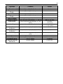
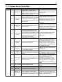
2.6.1 Grouped Alarms and Derived Controls
Your NetMediator's 8 control relays operate based on derived logic for preconfigured groups of your base
discrete, system, and analog threshold alarms (alarm groups 4-8). When wiring and configuring your NetMediator
RTD G5, keep in mind group and relay relationships to ensure proper operation.
For more information about Groups, see the Defining Point Groups section of this Manual.
Note: While relationships between groups and relays are predetermined, you may edit descriptions, set, and clear
messages for your alarm groups from the Groups menu in the web interface without altering group-relay
relationships. For your relays, you can determine whether or not your relays will send SNMP traps when their
state changes without affecting relay logic.
Group
Members
Group Name
Set
Message
Clear
Message
Echoed
Relays
Analogs 1, 2,
3, 7
Alarm
Clear
All's Well (sys)
Alarm
Clear
7, 8
Airflow
Sensors
Alarm
Clear
8
4
Base Analogs channels 1, 2, 3, 7
5
System Alarms (Display 11) 36, 40,
56, & 57
6
Discrete Alarms
7
All minor temperature threshold alarms
from RTD 32 DX expansion analog
channels
Minor Temp
Alarm
Clear
6
8
All major temperature threshold alarms
from RTD 32 DX expansion analog
channels
Major Temp
Alarm
Clear
1-5
Default alarm groups for the NetMediator RTD G5 and RTD 32 DX Expansions
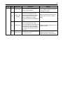
10
Relay (display
11)
Logic
Group
1
_OR G8
Operates relay when an alarm condition is present in group 8.
2
_OR G8
Operates relay when an alarm condition is present in group 8
3
_OR G8
Operates relay when an alarm condition is present in group 8.
4
_OR G8
Operates relay when an alarm condition is present in group 8.
5
_OR G8
Operates relay when an alarm condition is present in group 8.
6
_OR G7
Operates relay when an alarm condition is present in group 7
_NO G5
Relay operates when there are no alarm conditions present in alarm group 5.
(All points clear)
_OR G5 G6
Operates relay when an alarm condition is present in group 5 or group 6
7
8
Default relay logic for the NetMediator RTD G5
Default Derived Logic:
DPS Telecom does not recommend editing your NetMediator's default alarm groups or relay logic without
expressed direction from DPS Telecom Support. However, if you edit your NetMediator's relay logic, you can
return your relays to their default logic from the TTY interface. For more information on restoring your
NetMediator's default derived logic, see the section of your NetMediator's hardware manual titled Restoring
Default Derived Logic.
11
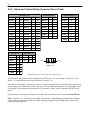
2.6.2 Alarm and Control Relay Connector Pinout Table
Discretes 1–25
Discretes 25–32
RTN ALM
RTN
ALM
RTN
ALM
Control Relays 1–8
NO/NC
CO
ALM 1
1
26
ALM 13
13
38
ALM 25
1
26
CTRL 1
9
34
ALM 2
2
27
ALM 14
14
39
ALM 26
2
27
CTRL 2
10
35
ALM 3
3
28
ALM 15
15
40
ALM 27
3
28
CTRL 3
11
36
ALM 4
4
29
ALM 16
16
41
ALM 28
4
29
CTRL 4
12
37
ALM 5
5
30
ALM 17
17
42
ALM 29
5
30
CTRL 5
13
38
ALM 6
6
31
ALM 18
18
43
ALM 30
6
31
CTRL 6
14
39
ALM 7
7
32
ALM 19
19
44
ALM 31
7
32
CTRL 7
15
40
ALM 8
8
33
ALM 20
20
45
ALM 32
8
33
CTRL 8
16
41
ALM 9
9
34
ALM 21
21
46
FUSE
17
42
ALM 10
10
35
ALM 22
22
47
ALM 11
11
36
ALM 23
23
48
ALM 12
12
37
ALM 24
24
49
GND
25
50
Analogs 1–6
ADC
+
Analogs 7–8
–
ADC
–
+
ADC 1
19 44
7
7–
7+
ADC 2
20 45
8**
8–
8+
ADC 3
21 46
ADC 4**
22 47
ADC 5**
23 48
ADC 6**
24 49
GND
25 50
ANA 7 –
ANA 8 +
ANA 7 +
ANA 8 –
Analogs 7–8
Alarm and control relay connector pinout for G5
The table above shows pinouts for the 50-pin connectors "Discretes 1–24" and "Analogs 1–6/Discretes 25–32/
Relays 1–8," and the pinout for the four-pin connector "Analogs 7–8."
Note that the NetMediator's control relays can be set for either Normally Open or Normally Closed operation. By
factory default, your NetMediator's control relays are set for Normally Open operation. You can configure relays
for Normally Closed operation at the hardware level by resetting a jumper on the NetMediator RTD G5 circuit
board.
For instructions on resetting control relays for Normally Closed operation, see the section titled Control Relays.
ADC** channels 4, 5, 6, and 8 may be unavailable for external use. Optional integrated temperature and battery
sensors, operate on these four channels.For details regarding your unit's hardware build, please reference the
product description appendix.
12
2.6.3 Discretes 1–24 Connector Pinout Diagram
RTN 1
RTN 2
RTN 3
RTN 4
RTN 5
RTN 6
RTN 7
RTN 8
RTN 9
RTN 10
RTN 11
RTN 12
RTN 13
RTN 14
RTN 15
RTN 16
RTN 17
RTN 18
RTN 19
RTN 20
RTN 21
RTN 22
RTN 23
RTN 24
GND
1
2
3
4
5
6
7
8
9
10
11
12
13
14
15
16
17
18
19
20
21
22
23
24
25
26
27
28
29
30
31
32
33
34
35
36
37
38
39
40
41
42
43
44
45
46
47
48
49
50
ALM 1
ALM 2
ALM 3
ALM 4
ALM 5
ALM 6
ALM 7
ALM 8
ALM 9
ALM 10
ALM 11
ALM 12
ALM 13
ALM 14
ALM 15
ALM 16
ALM 17
ALM 18
ALM 19
ALM 20
ALM 21
ALM 22
ALM 23
ALM 24
GND
Pinout Diagram for Discretes 1–24 connector
13
2.6.4 Analogs1–6/Discretes 25–32/Relays 1–8 Connector Pinout
Diagram
RTN 25
1
RTN 26
2
RTN 27
3
RTN 28
4
5
RTN 29
RTN 30
6
7
RTN 31
8
RTN 32
CTRL 1 NO 9
CTRL 2 NO 10
CTRL 3 NO 11
CTRL 4 NO 12
CTRL 5 NO 13
CTRL 6 NO 14
CTRL 7 NO 15
CTRL 8 NO 16
FUSE NO 17
Unused
18
19
ANA 1 +
ANA 2 +
20
21
ANA 3 +
ANA 4 +
22
ANA 5 +
23
24
ANA 6 +
25
GND
26
27
28
29
30
31
32
33
34
35
36
37
38
39
40
41
42
43
44
45
46
47
48
49
50
ALM 25
ALM 26
ALM 27
ALM 28
ALM 29
ALM 30
ALM 31
ALM 32
CTRL 1 CO
CTRL 2 CO
CTRL 3 CO
CTRL 4 CO
CTRL 5 CO
CTRL 6 CO
CTRL 7 CO
CTRL 8 CO
FUSE CO
Unused
ANA 1 –
ANA 2 –
ANA 3 –
ANA 4 –
ANA 5 –
ANA 6 –
GND
Pinout Diagram for Discretes 25–32/Relays 1–8 connector
14
2.6.5 Analog Dipswitches
By default, your NetMediator's analog inputs measure voltage. You can, however, configure them to measure a
current loop instead by flipping dipswitches accessible via the NetMediator's top sliding panel. For milliamp
(current loop) sensor operation on any analog channel , the dipswitch in the up (ON) position. For voltage
operation, place the dipswitch in the down (OFF) position.
You can access the analog dipswitches via the sliding hatch panel on top of the unit
WARNING: Do not place dipswitches in the upward, ON position (current loop mode) unless you are
sure your sensors are designed to measure a current loop. Placing a dipswitch in the ON position
inserts a 250 ohm resistor across the input line. Any voltage beyond 5V or 20 mA will damage
components.
15
2.6.6 Integrated Temperature and Battery Sensor (Optional)
The external temperature sensor
The NetMediator RTD G5 product line is available with optional integrated sensors to monitor internal
temperature, external temperature, and current draw at the NetMediator's power input.
Note: Integrated sensors are options available only if ordered for your NetMediator RTD G5 RTU. You cannot
add or remove them from the final product.
Each integrated sensor ordered with your NetMediator RTD G5 occupies one of the unit's 8 analog channels.
Sensor Function
Analog Input
Internal Temperature
analog input 4
Power Feed A
analog input 5
Power Feed B
analog input 6
External Temperature
analog input 8
Integrated sensor analog channels
2.6.6.1 Analog Step Sizes
The NetMediator's analog inputs are accurate to within +/- 1% of the analog input range.
Analog Step Sizes and Accuracy
Input Voltage Range
Resolution (Step Size)
Accuracy
0-5 V
.0015 V
+/- .05V
5-14 V
.0038 V
+/- .14V
14-30 V
.0081 V
+/- .30V
30-70 V
.0182 V
+/-.70V
70-90 V
.0231 V
+/-.90V
Analog step sizes and accuracy
16
2.7 Data Ports
Data ports 1–8
The NetMediator's eight data ports provide reach-through terminal server functionality for connecting multiple
simultaneous users to external equipment via Telnet over LAN. Each port can function as a proxy connection to
an external device, a craft port, a channel port, a TCP or UDP reach-through port. The NetMediator RTD G5 can
support simultaneous proxy connections for up to eight users.
NetMediator RTD G5 data ports are available in Yost RS-232, RS-485, and 4-wire 202 RJ45 connections, factory
set according to your preferences/build option. See the Port Allocation section of this manual for help identifying
the data port types on your particular NetMediator RTD G5 build.
Pinouts for Data Ports on the NetMediator RTD G5
Yost RS-232 RJ45 Connector
Yost RS-485 RJ45 Connector
8 RTS (Request to Send)
7 DTR (Data Terminal Ready)
6 TXD (Transmit Data)
5 GND (Ground)
4 GND (Ground)
3 RXD (Receive Data)
2 DSR (Data Set Ready)
1 CTS (Clear to Send)
8 TX- (Transmit -)
7 N/C (Not Connected)
6 RX- (Receive -)
5 GND (Ground)
4 GND (Ground)
3 RX+ (Receive +)
2 N/C (Not Connected)
1 TX+ (Transmit +)
Yost 4-Wire 202 Connector
8 TX+ (Transmit +)
7 N/C (Not Connected)
6 RX- (Receive -)
5 GND (Ground)
4 GND (Ground)
3 RX+ (Receive +)
2 N/C (Not Connected)
1 TX- (Transmit -)
Data port pinouts
17
Location of Pin 1 on RJ-45
Connector
DB9 RS-232
RX
GND
TX
5 4 321
98 7 6
RTS
CTS
Pin # Signal
Description
1
2
3
4
5
6
7
8
9
Not connected
Transmit data
Recieve Data
Not connected
Ground
Not connected
Clear to send
Request to send
Not connected
TX
RX
GND
CTS
RTS
DB9 RS-232 Pinout (Craft Port Only)
2.7.1 Port Allocation
The Port Allocation Sticker is located on the top of the unit in the back left corner. This sticker includes your part
number (D-PK-NM832-#####.#####), specifying your build option. The table below it lists data port allocation.
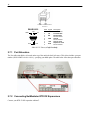
2.7.2 Connecting NetMediator RTD DX Expansions
Connect your RTD 32 DX expansions to Port 7.
18
2.7.3 GLD/ECU Expansion Port (RS-485)
If you are using a General LCD Displays (GLD) or Entry Control Units (ECU), connect them to the GLD/ECU
port. Both types of devices can be chained together. You can connect up to 13 GLD units or 8 ECUs to your
NetMediator's GLD/ECU port.
GLD/ECU Port
Data Port Pinout
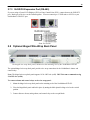
2.8 Optional Hinged Wire-Wrap Back Panel
The hinged wire-wrap back panel, mounted on the mounting rack of the NetMediator RTD G5
The optional hinged wire-wrap back panel provides wire-wrap connections for the NetMediator's alarms and
control relays.
Note: The hinged wire-wrap back panel supports 18-26 AWG wire (solid). DPS Telecom recommends using
24 AWG wire (solid).
To connect alarms and control relays to the wire-wrap panel:
1. Mount the hinged wire-wrap back panel on the mounting rack of the NetMediator RTD G5.
2. Close the hinged back panel and lock in place by turning the black plastic locking swivel to the vertical
position.
3. Connect discrete alarms, analog alarms, and control relays to the two pin blocks.
19
Suggested Wire Wrapping Tools
2.8.1 Lexan Wire-Wrap Cover
Spacer
Lexan panel
Lexan panel bracket
Securing screw
Lexan panel assembly
Once you've wired your alarms, analog inputs, and control relays, you can cover your connections with the Lexan
cover. Simply attach the cover to the included mounting clips and connect to the rear of the hinged panel.
20
2.9 Control Relays
Adjustable jumpers on the NetMediator RTD G5 circuit board
By default, the NetMediator's Control Relays are configured for Normally Open (N/O) operation. You can set
them for normally closed (N/C) operation via jumpers on the NetMediator's circuit board.
You can access your NetMediator's relay jumpers from the hatch panel on the top of the unit. Remove top screw
on hatch panel and rotate hatch cover until you can easily reach the jumpers.
Hatch Panel Access on Top of the NetMediator RTD G5 Chassis
WARNING: Always observe anti-static precautions whenever opening the unit.
21
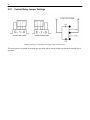
2.9.1 Control Relay Jumper Settings
Jumper settings for analog alarm inputs and control relays
The open position corresponds to normally open operation, and the closed position corresponds to normally closed
operation.
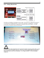
22
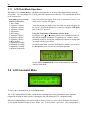
3 LCD Display
NetMediator RTD G5 Front Panel LCD
The front panel LCD displays the current alarm and control status and provides a command menu for controlling
the NetMediator's basic functions.
Using the LCD command menu
The four buttons surrounding the front panel LCD are used to access the LCD Command Menu. To access the
menu, press the Menu button. To scroll the menu, use the
and buttons. To select a menu command, press
the Sel (Select) button.
Standard Prompt
When no Command Menu item is selected and no alarms or relays are active, the LCD displays the firmware
version and the standard prompt, Press MENU for front panel options.
Controlling Display Speed
The scroll speed can be temporarily increased by pressing and holding the
button while the message is active.
3.1 Alarm and Control Status Messages
The LCD will display messages to indicate active alarm and control relay status.
Discrete Alarms:
If there are any standing discrete alarms, the display will read "Discrete Alarms:",
followed by the user-defined descriptions of the standing alarm points.
Relays:
If there are any latched relays, the display will read "Relays:", followed by the
user-defined descriptions of the latched relays.
Ping Alarms:
If any ping targets have failed to respond within the specified time, the display
will read "Ping Alarms:", followed by the user-defined descriptions of the ping
targets.
Analogs:
If any analog channels have crossed a threshold value, the display will read
"Analogs", followed by the user-defined description of the analog channel, the
channel's last voltage reading, and a letter indicating which threshold the channel
has crossed.
Analog thresholds are represented by the following characters:
Major Over:
Minor Over:
Minor Under:
Major Under:
a capital O
a lower-case o
a lower-case u
a capital U
23
3.1.1 LCD Point Mode Operation
When the LCD is in Point Mode, it will display only points that are in alarm, rather than full alarm and relay
descriptions. You can configure the LCD for point mode operation from either the TTY command line interface
or the web interface.
Point Mode processes alarm
windows in this order:
1. Base Alarms
2. Expansion 1 Alarms
3. Expansion 2 Alarms
4. Expansion 3 Alarms
5. Ping Alarms
6. Base Relays
7. Expansion 1 Relays
8. Expansion 2 Relays
9. Expansion 3 Relays
10.Base Analogs
11.Expansion 1 Analogs
12.Expansion 2 Analogs
13.Expansion 3 Analogs
14.Network Link Down
Only active alarms will appear on the LCD. If no alarms are active, a "no
alarms active" message will appear.
You can determine the length of time for which each point will appear on
the screen 1-60 seconds (default is 2 seconds) by setting the LCD Delay
time via the TTY interface.
Using the Front Panel LCD buttons in Point Mode
Pressing the SEL, , or
buttons will force the NetMediator RTD G5
back into Scroll Mode (standard LCD operation) for 3 minutes. This is
particularly useful for viewing the configured descriptions or analog values
associated with the active alarms.
If, while in Point Mode, you enter Scroll Mode by mistake, you can press
the Menu button twice to revert to Point Mode operation.
See the TTY Command Mode section of this manual for commands
related to Point Mode.
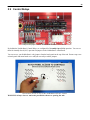
3.2 LCD Command Menu
LCD display
To access the Command Menu, press the Menu button.
The LCD Command Menu provides commands for controlling some of the NetMediator's basic functions:
temporarily silencing the alarm speaker, rebooting the unit, and running the TTY configuration utility.
When no Command Menu item is selected and no alarms or relays are active, the LCD displays the firmware
version and the Standard Prompt, Press MENU for front panel options. (See example above.)
24
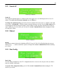
3.2.1 Sound off
Sound Off command
Sound off
The Sound off command suppresses sounds from the alarm speaker for a user-defined period of 10, 20, or 30
minutes. To scroll to the next menu command, press the
button.
To change the Sound off setting, press Sel to select the command. The arrow cursor (>) will move to the right
of the colon (:) in Sound off: to indicate that the command submenu is selected. Press the
and
buttons to
scroll through the Sound off time period options. Select 0 minutes to allow all sounds. When the time period you
want is displayed, press Sel to make your selection. To exit the Command Menu without changing the Sound
off setting, press Menu.
3.2.2 Reboot
Reboot command
Reboot
The Reboot command reboots the NetMediator RTD G5. Press Sel. The LCD will briefly display the message
Rebooting ..., and the normal boot sequence will begin. To exit the Command Menu without rebooting,
press Menu.
3.2.3 Run Config
Run Config command
Run Config
The Run Config command forces the TTY configuration interface to run over the craft port at the user defined
baud rate (default is 9600 baud).
To run the TTY configuration utility, press Sel. To exit the Command Menu without running the TTY
interface, press Menu.
25
3.2.4 Contrast
The Contrast command provides controls for adjusting the contrast of the LCD.
To adjust the contrast, press Sel to select the command. The arrow cursor (>) will move to the right of the
colon (:) in Contrast: to indicate that the command submenu is selected. Press the
or
button until
you're satisfied with the contrast setting, then press Sel to make your selection. To exit the Command Menu and
revert to the default contrast setting, press Menu.
4 Alarm Speaker
The NetMediator's alarm speaker emits distinctive tones under two conditions
1.
If there is an Ethernet connection failure, the speaker will emit a high-low warbling tone. Press
any front panel button to silence the speaker.
2. If an alarm occurs, the speaker will emit an intermittent beep. Press any front panel button to silence
the speaker. If you do not silence the speaker, the beep will continue for the user defined duration (default
is a 6 second duration). Silencing the speaker will allow the next alarm, if any, to sound.
26
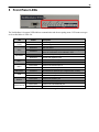
5 Front Panel LEDs
Front panel LEDs
The NetMediator's front panel LEDs indicate communication and alarm reporting status. LED status messages
are described below in Table 9.A.
LED
Config
Alarm
Expansion
Net 1
Net 2
LNK Alarm
Craft
Modem
Data Ports1-8
Status
Description
Blink Green
Valid Configuration
Blink Red
Invalid Configuration
Blink Red
New COS alarm*
Solid Red
One or more standing alarms Note: You must configure
alarms for notifications to be reflected in LED
Blink Green
Transmit over expansion port
Blink Red
Receive over expansion port
Blink Green
Transmit over Ethernet port 1
Blink Red
Receive over Ethernet port 1
Blink Green
Transmit over Ethernet port 2
Blink Red
Receive over Ethernet port 2
Solid Red
No Ethernet link detected (for configured Net1 or Net2)
Blink Green
Transmit over craft port
Blink Red
Receive over craft port
Blink Green
Transmit over Modem port
Blink Red
Receive over Modem port
Blink Green
Transmit over indicated data port
Blink Red
Receive over indicated data port
Front panel LED Status message descriptions
27
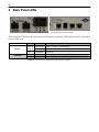
6 Back Panel LEDs
Back panel LEDs for Power (left) and Ethernet connections
The back panel LEDs indicate the status of power and Ethernet connections. LED status messages are described
below in Table 10.A.
Power
10/100 Net
LED
Status
Power A
and/or B
Solid Green
FA
Solid Red
Net1
Blink Green
Activity over indicated integrated Ethernet port
Net2
Solid Green
Link detected
Off
Description
Polarity is correct on power feed A
No Power or Polarity Reverse
Fuse failure
Table 10.A. Back panel LED Status message descriptions
28
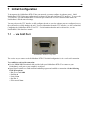
7 Initial Configuration
To incorporate the NetMediator RTD G5 into your network, you must configure its ethernet port(s). Initial
NetMediator RTD G5 ethernet configuration is performed via the unit's integrated TTY interface. To access the
TTY interface, you will establish either a serial craft port connection or a LAN connection that mimics the
NetMediator's default network settings.
You may also use the TTY interface to fully configure the unit or, once the ethernet ports are configured, access
the web interface to fully database the unit. For more information about the TTY interface, see the section titled
Configuring the NetMediator RTD G5 via TTY. For information about the unit's web interface, see the
NetMediator's Web Interface manual.
7.1 ... via Craft Port
NetMediator RTD G5 Craft Port
The easiest way to connect to the NetMediator RTD G5 for initial configuration is via a craft serial connection.
To establish a craft serial connection:
Use the DB9M-DB9F download cable provided with your NetMediator RTD G5 to connect to your
NetMediator's craft port to your computer's serial port.
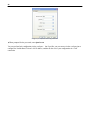
Open HyperTerminal or a similar terminal emulation program and establish a connection with the following
COM port options:
o Bits per second: 9600
o Data bits: 8
o Parity: None
o Stop bits: 1
o Flow control: None
29
Configure your craft connection in HyperTerminal
When prompted for the password, enter dpstelecom
You can perform basic configuration via the craft port - but if you like, you can connect via the craft port just to
configure the NetMediator's Private LAN IP address, and then do the rest of your configuration via a LAN
connection.
30
7.2 ... via LAN
Ethernet ports
You can also connect to the NetMediator RTD G5 over a LAN connection for initial configuration.
Note: NET1's default IP address is: 192.168.1.100
If you have physical access to the NetMediator RTD G5, it is easier to connect to the unit through the craft
port and assign it an IP address than it is to initially connect to the unit via LAN. Once you have assigned the
NetMediator's ethernet settings, you may then easily complete the unit's configuration over LAN. For help
establishing a craft serial connection with your NetMediator RTD G5, see the previous section of this manual.
If you DON'T have physical access to the NetMediator RTD G5, you can establish an initial LAN
connection with the unit by temporarily changing your PC's IP address and subnet mask to match the
NetMediator's default settings.
To establish an Initial TTY connection to the NetMediator RTD G5 via LAN:
1. Look up your PC's current IP address and subnet mask, and write the information down; you will
temporarily change your PC's IP and subnet mask to access the NetMediator RTD G5, and you'll want
this information so you can easily restore your previous settings.
2. Reset your PC's IP address to 192.168.1.200.
3. Reset your PC's subnet mask to 255.255.0.0. You may have to reboot your PC to apply your changes.
4. Once the IP address and subnet mask of your computer coincide with the NetMediator's, you can access
the NetMediator RTD G5 via Telnet session at port 2002 or via Web browser using the NetMediator's
default IP address, 192.168.1.100.
5. When prompted for the password, type dpstelecom and press Enter.
6. Provision the NetMediator RTD G5 with the appropriate information (see Ethernet Configuration later
in this chapter for more information). Once you've configured your NetMediator's ethernet connection,
you may revert your computer's IP address and subnet mask back to their original settings - the
information you wrote down in Step 1.
31
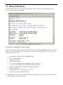
7.3 Ethernet Port Setup
The NetMediator RTD G5 must be assigned appropriate IP, subnet, and gateway information before it can
operate in your LAN/WAN environment.
Configure the Ethernet port parameters
To assign your NetMediator's network settings:
Note: The following steps assume you have established a connection with the NetMediator RTD G5. If you have
not done so, see the previous sections in this chapter to connect to your NetMediator RTD G5 either via serial
craft connection or over LAN.
1. When prompted for the password, enter dpstelecom
2. Type C for the C)onfig menu.
3. Type E for E)dit menu.
4. Type E for port settings,
Press 1 to edit settings for the NetMediator's Net 1 ethernet port
Press 2 to edit settings for the NetMediator's Net 2 ethernet port.
5. Configure the Unit IP address, Subnet mask, and Default gateway.
6. ESC to the main menu.
7. When prompted to save your changes, press Y (yes).
8. Press R to reboot the NetMediator RTD G5.
Once the unit reboots, you can resume NetMediator RTD G5 configuration, access the unit over IP (Telnet TTY
or Web Interface), and poll it via T/Mon.
32
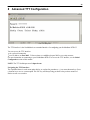
8 Advanced TTY Configuration
The TTY interface
The TTY interface is the NetMediator's text terminal interface for configuring your NetMediator RTD G5.
You can access the TTY interface:
via craft serial connection
over IP address on Port 2002. Telnet sessions are established on port 2002 as a security measure.
For more instructions on connecting to your NetMediator RTD G5 to access the TTY interface, see the Initial
Configuration section of this manual.
NOTE: The TTY default password is dpstelecom.
Navigating the TTY Interface:
The capitalized letters in each menu option, before, or enclosed in, parentheses ( ), are menu shortcut keys. Press
a shortcut key to access a menu option. The ESC key will always bring you back to the previous menu level.
Entries are not case sensitive.
33
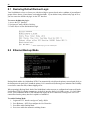
8.1 Restoring Default Derived Logic
Your NetMediator's relays are factory set with derived logic to operate based on the conditions of preconfigured
groups of base alarms, system alarms, and analog thresholds. If you edit the factory-defined relay logic in error,
you can restore the default relay logic via the TTY interface.
To restore default relay logic:
1. Access the TTY Interface.
2. Navigate to C)onfig > E)dit > Re(L)ay.
3. Choose Y)es to restore default derived logic.
Restore default relay logic via the TTY Interface
8.2 Ethernet Backup Mode
Enable "Backup Mode" to automatically switch between Net1 and Net2.
Backup Mode enables the NetMediator RTD G5 to automatically switch from the primary network path (Net1) to
the backup network path (Net2) should the primary LAN connection fail, allowing you to maintain critical visibility
even when a connection fails, without skipping a beat.
When operating in Backup Mode, both of the NetMediator's ethernet ports are configured and connected, but the
NetMediator RTD G5 will only communicate via the Net1 interface until a LAN failure occurs. If a LAN failure
occurs, your NetMediator RTD G5 will automatically employ the Net2 connection, reverting to the Net1 LAN
connection when the primary interface's uplink is reestablished.
To enable Backup Mode
1. Login to the TTY interface and go to C)onfig > E)dit.
2. Go to E)thernet > NET(2) to configure the Net 2 Interface.
3. Press B to enable Backup Mode
4. Press A to enable the automatic switching feature.
34
8.3 Edit PPP Port
From the E)dit menu, you can press P to edit the baud rate of the port you've chosen for PPP pass through.
Edit your PPP port
To configure your PPP port:
1. Navigate to the PPP menu: C)onfig > E)dit > P)PP menu
2. Press P to select the P)ort, you wish to configure for PPP operation.
3. Configure your port according to the remainder of the menu options in the PPP tab. See the table below for a
list of available options in the PPP menu.
Select the baud rate for your PPP port
35
8.4 RADIUS Configuration
RADIUS (Remote Authentication Dial In User Service) is an industry-standard way to manage logins to many
different types of equipment from a central user database.
With RADIUS enabled, the NetMediator RTD G5 will prompt users for both a username and password to logon
to the unit. The NetMediator RTD G5 will then verify entered username and password against the RADIUS
database, instead of its own local user database. The NetMediator RTD G5 will only use its own local password
database for serial craft access.
Your NetMediator RTD G5 supports access to two RADIUS authentication servers, labeled by a 1 and 2 after
each menu option in the RADIUS menu. All menu options ending in 1 refer to RADIUS Server 1, and all options
ending in 2 apply to Radius Server 2.
The RADIUS configuration menu using the TTY interface.
Hotkey
Option
R
R)etry
T
T)imeout
A or B
IPA
C or D
Port
E or F
Interface
G or H
Secret
Description
Global Settings
How many times the RADIUS server will retry a logon attempt
Enter in the number of seconds before a logon request is timed
out
Servers 1 / 2
Enter the IP address of your RADIUS servers.
Enter the Port address for your Radius servers. Port 1812 is
the industry-standard port for RADIUS authentication.
Choose the Ethernet Interface to which the RADIUS information
will apply, Net1 or Net2.
Enter the RADIUS secrets.
RADIUS logon screen prompts for a Username and Password.
36
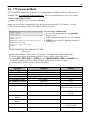
8.5 TTY Command Mode
TTY Command line Mode offers an alternate way of configuring the NetMediator RTD G5. This interface is
scriptable, and is recommended for advanced users. Entries in Command Mode are NOT case sensitive.
To Enter Command Line Mode:
From the TTY Interface's base menu, press CTRL+C
Note: You can only enter Command Line Mode from the top-level menu of the TTY interface. Pressing
CTRL+C from any other level of the TTY interface will have no affect.
Tips for using Command Mode
To view all acceptable operations, type get help,
then press Enter.
Invalid commands will return "Error" as the response.
A CRLF is sent by the RTU following all responses
from the RTU.
To enter Command Line mode, login to the TTY, then
press Ctrl+C.
Limited data validation is in place in the TTY interface. Use caution when setting variable values.
You may need to reboot the NetMediator RTD G5 for new variable values to take effect.
Changing REF1, REF2, DISP1, or DISP2 affects the MAJOR, MINOR, OVER, and UNDER alarm
thresholds. Changing any of these settings should be checked and re-entered as required.
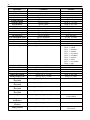
In the table below, variables (params) are noted in brackets.
Operation
Help
Initialize NVRAM
Write NVRAM
Read NVRAM
View System Up Time
View Firmware Version
Data Port Description
Data Port Baud
Command
get help
init nvram {g2}
set nvram
get nvram
get sysuptime
get prodid
{get,set} dataport {1...9} desc
{get,set} dataport {1...9} baud
Data Port Format
{get,set} dataport {1...9} wfmt
Data Port RTS Head
(msec)
Data Port RTS Tail
(msec)
Data Port Type
{get,set} dataport {1...9} rtshead
Params
None
None
None
None
None
None
string {0...15} chars
{1200,300,600,1200,2400,4800,
9600,19200,38400,57600,115200
}
{8n1,8n2,7n1,7e1,7o1,8
o2,8o1}
{0..255}
{get,set} dataport {1...9} rtstail
{0..255}
{get,set} dataport {1...9} type
# of NetMediator
{get,set} ngddx
{off,tcp,ptcp,htcp,rtcp,udp,chan,
crft,cap,ecu,sps8}
{0...3}
37
Operation
Expanders
# of GLD or BSU
Timed Tick Period
System Name
System Location
System Contact
System Phone
Reboot
DCP Unit ID
DCP Port Number
DCP Port Type
DCP Protocol
DCP Autonomous Time
Network Time IPA
Username
Password
Access Rights
Network IPA
Subnet Mask
Gateway IPA
Proxy Base
Analog Description
Analog Display Unit
Analog Major Under
Threshold
Analog Minor Under
Threshold
Analog Minor Over
Threshold
Analog Major Over
Threshold
Analog Trap
Analog Primary
Notification
Analog Secondary
Location
Analog Polarity
Command
Params
{get,set} gld
{get,set} timed tick
{get,set} name
{get,set} location
{get,set} contact
{get,set} phone
set reboot
{get,set} dcpaddr
{get,set} dcpport
{get,set} dcptype
{get,set} dcpprot
{get,set} dcpautotm
{get,set} ntpipa
{get,set} username {1...16}
set password {master, 1...16}
{get,set} access {1...16}
{get,set} net {1,2} ipa
{get,set} net {1,2} subnet
{get,set} net {1,2} gateway
{get,set} proxybase
{get,set} alg {1...8} desc
{get,set} alg {1...8} unit
{get,set} alg {1...8} thres mju
{0...16}
{0...60} {min}
string {0..31} chars
string {0..31} chars
string {0..31} chars
string {0..20} chars
None
{0...255}
{1..32767}
{udp,tcp,serial}
{dcpx,dcpf,dcpe}
{0..120} {sec,min}
IP Address
string {0...18} chars
string {0..15} chars
{0000..01ff} where
Bit.0 – 1=admin
Bit.1 – 1=database
Bit.2 – 1=monitor
Bit.3 – 1=rly control
Bit.4 – 1=reachthru
Bit.5 – 1=modem
Bit.6 – 1=telnet
Bit.7 – 1=sd_monitor
Bit.8 – 1=ppp
IP Address
Subnet
Gateway
{1..32767}
string {0..48} chars
string {0..3} chars
{-94.0000...94.0000}
{get,set} alg {1...8} thres mnu
{-94.0000...94.0000}
{get,set} alg {1...8} thres mno
{-94.0000...94.0000}
{get,set} alg {1...8} thres mjo
{-94.0000...94.0000}
{get,set} alg {1...8} trap
{get,set} alg {1...8} pri
0=trap disabled
1=trap enabled
{0...8}
{get,set} alg {1...8} sec
{0...8}
{get,set} alg {1...8} polarity
0=Normal
1=Reversed
38
Operation
Command
{get,set} alg {1...8} group {mju,mnu, mno,mjo}
Analog Group Number
{get,set} alg {1...8} ref1
Analog Reference 1 VDC
{get,set} alg {1...8} disp1
Analog Reference 1
Display
{get,set} alg {1...8} ref2
Analog Reference 2 VDC
{get,set} alg {1...8} disp2
Analog Reference 2
Display
{get,set} alg {1...8} deadband
Analog Deadband
{get,set} alm {base,exp1,exp2,exp3} {1...64} desc
Alarm Description
{get,set} alm {base,exp1,exp2,exp3} {1...64}
Alarm Polarity
polarity
{get,set} alm {base,exp1,exp2,exp3} {1...64} trap
Alarm Trap
Alarm Primary
Notification
Alarm Secondary
Notification
Alarm Group
Global Trap IP Address
Global Trap Format
LCD Display Mode
LCD Delay Time (for
Point Mode)
Params
{1...8}
Number
Number
Number
Number
{get,set} alm {base,exp1,exp2,exp3} {1...64} pri
{0.1...9.9}
string {0...48} chars
0=Normal
1=Reversed
0=trap disabled
1=trap enabled
{0...8}
{get,set} alm {base,exp1,exp2,exp3} {1...64} sec
{0...8}
{get,set} alm {base,exp1,exp2,exp3} {1...64}
group
{get,set} trap {1,2} ipa
{get,set} trap {1,2} format
{get,set} lcdmode
{get,set} lcddelay
{1...8}
IP Address
{v1, v2c, v2cinf,v3}
{scroll,point}
{1..60} {sec}
39
Examples:
You want to find out how long this NetMediator
RTD G5 has been running (since last rebooted.) Get
system uptime by typing get sysuptime, then
press Enter.
You want to see the alarm description for Base
Alarm 1. To see the description, type get alm base
1 desc
You want to set the Global Trap IP Address to
126.10.230.133. To enter this, type set trap 1 ipa
= 126.10.230.133
You want to change the LCD mode from Scroll
(default) to Point Mode. To change this, type set
lcdmode = point
40
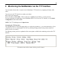
9 Monitoring the NetMediator via the TTY Interface
You can monitor alarms and set controls via the NetMediator's TTY interface by navigating to C)onfig > M)
onitor.
You can access the TTY interface to monitor your alarms:
Via craft serial connection
Over IP address on Port 2002. Telnet sessions are established on port 2002 as a security measure.
For more instructions on connecting to your NetMediator RTD G5 to access the TTY interface, see the Initial
Configuration section of this manual.
NOTE: The TTY default password is dpstelecom.
Navigating the TTY Interface:
The capitalized letters in each menu option, before, or enclosed in, parentheses ( ), are menu shortcut keys. Press
a shortcut key to access a menu option. The ESC key will always bring you back to the previous menu level.
Entries are not case sensitive.
The following sections provide an explanation of the menu options available in the monitoring section of the TTY
interface.
The monitor menu allows status checking on all elements
41
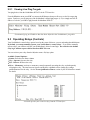
9.1 Base Alarm Status
View the status of your discrete alarms from the M)onitor menu > A)larms option. Under Status, the word
Alarm will appear if an alarm has been activated and Clear will appear if an alarm condition is not present.
Points assigned to groups will display the user-defined status.
This example shows page two of the discrete alarms
9.2 Ping Targets
View the status of all your ping targets from the M)onitor menu > P)ing targets option. This screen displays the
ping target ID, description, and IP address. The Status column will display the condition of each ping target,
Alarm or Clear.
The Ping info submenu allows you to change ping targets
42
9.2.1 Viewing Live Ping Targets
You ping devices from the NetMediator RTD G5 via the TTY interface.
From the M)onitor menu, press ESC to return to the E)dit menu, then press P to access the live target ping
option. From here, you can ping any of the NetMediator's defined ping targets (1-32) or simply enter the IP
address of a device you'd like to ping from the NetMediator RTD G5.
Continuously ping an IP address that has been defined in the NetMediator's ping table
9.3 Operating Relays (Controls)
Your NetMediator's control relays operate based on the status of discrete, system, and analog threshold alarms.
By default, you cannot manually operate your NetMediator's control relays. If you wish to manually
operate relays, you will have to delete your NetMediator's derived control logic. Do not delete the default
relay logic without expressed direction from DPS Telecom.
You can activate your relays from the M)onitor menu > R)elays option.
Available Control Options:
S)tatus: Refreshes the Status column
O)pr - Operate: Operates the relay
R)ls - Release: Releases the relay
M)om - Momentary: activates a momentary control, temporarily operating the relay, and subsequently
releasing the relay. The time between Operate and Release commands can be changed by setting a
qualification timer for the relay. See the Event Qualification Timers section of your Web Interface manual
for details.
view and operate your control relays from the TTY interface
43
9.4 Monitoring Analogs
View the current reading and the alarm status of your analog devices by pressing N from the Monitor menu (M)
onitor menu > a(N)logs). The value shown is a snapshot of the channels measurement, not a real-time reading.
Refresh the readings by re-selecting the analogs option. An X in any of the threshold fields indicates an alarm.
This display allows you to monitor your eight analog inputs
9.5 Monitoring System Alarms
View the status of the NetMediator's system alarms by pressing S from the Monitor Menu (M)onitor menu > S)
ystem). The Status column will display the appropriate label for each alarm as determined by its point group.
System Alarms can be viewed from the M)onitor menu > S)ystem option
44
9.6 Monitoring Data Port Activity
You can view the status of the NetMediator's data ports by pressing O from the Monitor Menu. Enter the number
of the port you wish to view and press Enter.
The NetMediator RTD G5 provides an ASCII description under Transmit and Receive. Choose a) Transmit to
view data transmitted to another device. Choose b) Receive to view data received from another device.
Data port activity can be viewed from the M)onitor menu > p(O)rts option
9.6.1 Proxy Menu
You can create proxy connections to reach-through to the craft port, modem port or any of the other eight serial
ports from the P)roxy menu. You'll be able to monitor and control additional devices via proxy connection to the
NetMediator RTD G5. Data presented and handshaking will be specified by the connected device.
To cancel the proxy connection wait a half second, then quickly type @@@ and press ENTER.
Access devices connected to the eight data ports on the back panel through M)onitor menu > P)roxy
option
45
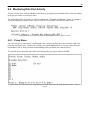
9.7 Monitoring the Accumulation Timer
The Accumulation Timer keeps a running total of the amount of time a designated point is in an alarm state. When
the alarm point exceeds the user-defined time threshold, the NetMediator RTD G5 will trigger an Accumulation
Event system alarm. From the Monitor menu, pressing C provides access to the Accumulation Timer,
displaying the amount of time a point has been in alarm, and allowing you to reset the timer.
Resetting the accumulation timer:
Press R from the a(C)cum.Timer menu.
Monitor and reset the Accumulator Timer
Field
Description
Display and Point
Reference
Indicates which alarm point is to be monitored.
Point Description
The user-defined description of the monitored alarm point.
Point Status
The current status of the monitored point.
Event Threshold
Amount of time allowed to accumulate before the system alarm,
“Accumulation Event” is triggered. Note: Maximum is 45 days.
Accumulated Time
The total time the monitored point has been in an ALARM state.
Accumulated Since
Indicates the last time the accumulation timer was reset.
Reset Accumulation
Timer
Selecting this option will reset the timer.
Field descriptions in the Accumulator Timer Settings
46
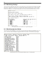
9.8 Event Logging
Choose E)vent log from the M)onitor menu to view the last 100 events posted to the NetMediator RTD G5,
including power up, base and system alarms, ping alarms, analog alarms, and issued controls. Posted events for the
various alarms include both alarm and clear status. Refer to the table below for event log field descriptions.
Note: All information in the event log will be erased upon reboot or a power failure.
Monitor the last 100 events recorded by the NetMediator RTD G5 from the M)onitor menu > E)vent log
option
Event Log Field
Evt
Description
Event number (1–100)
Date
Date the event occurred
Time
Time the event occurred
Grp
Alarm Group
State
State of the event (A=alarm, C=clear)
PRef
Point reference (See Appendix A for display descriptions).
Description
User defined description of the event as entered in the alarm point and
relay description fields.
Event Log field descriptions
47
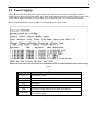
9.9 Debug Input and Filter Options
Debug Input Options
ESC
Exit Debug
B
Show BAC status points
T
Show task status
U
Show DUART information
R
Show network routing table
X
Clear debug enable bitmap. Turn all debug filters OFF
?
Display Options
Debug Filter Options:
a
(1) Alarm toggle switch. Shows posting of alarm data
A
(2) Analog toggle switch. Shows TTY interface debug
c
(3) Config toggle switch. Shows TTY interface debug
C
(4) Control relay toggle switch. Shows relay operation
d
(5) DCP responder toggle switch. Shows DCP protocol
D
(6) Device toggle switch. Shows telnet and proxy information and NGEditG5 serial communication.
e
(7) Expansion poller toggle switch. Shows NGDdx polling
E
(8) ECU Interrogator toggle switch. Shows BAC processing
f
(9) FTP Command toggle switch. Shows command string parsing
F
(10) FTP Data toggle switch. Shows FTP Read / Write
G
(11) GLD poller toggle switch. Shows GLD polling
h
(12) HTML debug switch. Shows Web Browser processing
H
(13) HWACS debug switch. Shows hardware access operation
i
(14) PING toggle switch
k
(15) Socket toggle switch. Shows current dcu resources
l
(16) LED toggle switch. Shows current LED state
L
(17) LCD display toggle switch. Shows LCD control and text
m
(18) Modem toggle switch. Shows modem vectored initialization
M
(19) Undefined
o
(20) Osstart toggle switch. Miscellaneous application debug, including NVRAM read and write operation, and
event posting
O
(21) Undefined
p
(22) SPORT toggle switch. Port init debug and channeled port debug
P
(23) PPP toggle switch. Shows PPP functioning
q
(24) QAccess toggle switch. Reserved for future use
Q
(25) Undefined
r
(26) Report toggle switch. Shows reporting event activity, including SNMP, pagers, email, etc. Also shows
PPP negotiation for NG client PPP mode.
s
(27) SNMP toggle switch. Reserved for future use
S
(28) STAK toggle switch. Shows network processing and IPA of arp requests. Also shows packets
discarded by Filter IPA.
t
(29) TERM toggle switch. Shows UDP/TCP port handling. The camera and network time (NTP) jobs also use
the TERM toggle switch
V
(30) Undefined
w
(31) HTTP toggle switch. Shows handling of web browser packets
W
(32) WEB toggle switch 2. Dump HTML text from web browser
48
Debug Input and Filter Options
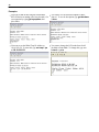
10 Backing Up NetMediator Configuration Data via FTP
1. From the Start menu on your PC, select RUN.
2. Type "ftp" followed by the IP address of the NetMediator RTD G5 you are backing up (e.g. ftp
126.10.120.199).
3. When the connection has been established, press Enter.
4. Enter the your password (the default password is dpstelecom), then press Enter.
5. Type binary and press Enter (necessary for NetMediator RTD G5 file transfer).
6. Type lcd and press Enter (this allows you to change the directory of your local machine).
7. Type get followed by the name you wish to define for the NetMediator RTD G5 backup file. Add the
extension ".bin" to the file name (e.g. get ngdbkup.bin) and press Enter.
8. After reloading, type bye and press Enter to exit.
Note: The backup file name can have a maximum of eight characters before the file extension.
10.1 Reloading NetMediator Configuration Data
1. From the Start menu on your PC, select RUN.
2. Type "ftp" followed by the IP address of the NetMediator RTD G5 you are backing up (e.g. ftp
126.10.120.199).
3. After the connection is made press Enter.
4. Enter the password of the NetMediator RTD G5 (default password is dpstelecom), then press ENTER.
5. Type "binary" and press Enter (necessary for NetMediator RTD G5 file transfer).
6. Type "lcd" and press Enter (this allows you to change the directory of your local machine).
7. Type "put" followed by the name you defined for the NetMediator RTD G5 backup file and press Enter
(e.g. put ngdbkup.bin).
8. Type "literal REBT" to reboot the NetMediator RTD G5.
9. After reloading, type "bye" and press Enter to exit.
49
11 Reference Section
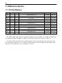
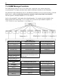
11.1 Display Mapping
Port
Address Display
Description
Set
Clear
99
1
1
Discrete Alarms 1-32
8001-8032
9001-9032
99
1
1
E16 DX Controls 1-16
8049-8064
9049-9064
99
1
2
Ping Table
8065-8096
9065-9096
99
1
3
Analog Channel 1**
8129-8132
9129-9132
99
1
4
Analog Channel 2**
8193-8196
9193-9196
99
1
5
Analog Channel 3**
8257-8260
9257-9260
99
1
6
Analog Channel 4**
8321-9324
9321-9324
99
1
7
Analog Channel 5**
8385-8388
9385-9388
99
1
8
Analog Channel 6**
8449-8452
9449-9452
99
1
9
Analog Channel 7**
8513-8516
9513-9516
99
1
10
Analog Channel 8**
8577-8580
9577-9580
99
1
11
Relays/System Alarms (See table below)
8641-8674
9641-9674
Display descriptions and SNMP Trap numbers for the NetMediator RTD G5
* The TRAP number ranges shown correspond to the point range of each display. For example, the SNMP Trap
"Set" number for alarm 1 (in Display 1) is 8001, "Set" for alarm 2 is 8002, "Set" for alarm 3 is 8003, etc.
** The TRAP number descriptions for the Analog channels (1-8) are in the following order: minor under, minor
over, major under, and major over. For example, for Analog channel 1, the "Set" number for minor under is 8129,
minor over is 8130, major under is 8131, and major over is 8132.
50
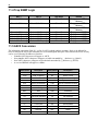
11.1.1 NetMediator RTD DX Expansion 1
Your RTD 32 DX Expansion's analog channels are databased on displays 12-27 for expansion 1 and 28-43 for
expansion 2.
Expansion analog channels use points 1-5 for the first channel, and 33-37 for the second channel in each 64 point
display, each corresponding to the trap numbers listed below. Analog thresholds are listed in the following order (14, 33-36): Minor Under, Minor Over, Major Under, and Major Over. The fifth bit for each analog channel is a trap
indicating the absence of a sensor on that channel.
Port
99
99
99
99
99
99
99
99
99
99
99
99
99
99
99
99
99
99
99
99
99
99
99
99
99
99
99
99
99
99
99
99
Address Display
Description
Points
Set
1
12
RTD 32 DX 1 Analog Channel 1
1-5
10001-10005
1
12
RTD 32 DX 1 Analog Channel 2
33-37
10006-10010
1
13
RTD 32 DX 1 Analog Channel 3
1-5
10011-10015
1
13
RTD 32 DX 1 Analog Channel 4
33-37
10016-10020
1
14
RTD 32 DX 1 Analog Channel 5
1-5
10021-10025
1
14
RTD 32 DX 1 Analog Channel 6
33-37
10026-10030
1
15
RTD 32 DX 1 Analog Channel 7
1-5
10031-10035
1
15
RTD 32 DX 1 Analog Channel 8
33-37
10036-10040
1
16
RTD 32 DX 1 Analog Channel 9
1-5
10041-10045
1
16
RTD 32 DX 1 Analog Channel 10
33-37
10046-10050
1
17
RTD 32 DX 1 Analog Channel 11
1-5
10051-10055
1
17
RTD 32 DX 1 Analog Channel 12
33-37
10056-10060
1
18
RTD 32 DX 1 Analog Channel 13
1-5
10061-10065
1
18
RTD 32 DX 1 Analog Channel 14
33-37
10066-10070
1
19
RTD 32 DX 1 Analog Channel 15
1-5
10071-10075
1
19
RTD 32 DX 1 Analog Channel 16
33-37
10076-10080
1
20
RTD 32 DX 1 Analog Channel 17
1-5
10081-10085
1
20
RTD 32 DX 1 Analog Channel 18
33-37
10086-10090
1
21
RTD 32 DX 1 Analog Channel 19
1-5
10091-10095
1
21
RTD 32 DX 1 Analog Channel 20
33-37
10096-10110
1
22
RTD 32 DX 1 Analog Channel 21
1-5
10101-10105
1
22
RTD 32 DX 1 Analog Channel 22
33-37
10106-10110
1
23
RTD 32 DX 1 Analog Channel 23
1-5
10111-10115
1
23
RTD 32 DX 1 Analog Channel 24
33-37
10116-10120
1
24
RTD 32 DX 1 Analog Channel 25
1-5
10121-10125
1
24
RTD 32 DX 1 Analog Channel 26
33-37
10126-10130
1
25
RTD 32 DX 1 Analog Channel 27
1-5
10131-10135
1
25
RTD 32 DX 1 Analog Channel 28
33-37
10136-10140
1
26
RTD 32 DX 1 Analog Channel 29
1-5
10141-10145
1
26
RTD 32 DX 1 Analog Channel 30
33-37
10146-10150
1
27
RTD 32 DX 1 Analog Channel 31
1-5
10151-10155
1
27
RTD 32 DX 1 Analog Channel 32
33-37
10156-10160
Display descriptions and Point numbers for the RTD 32 DX Expansion
Clear
11001-11005
11006-11010
11011-11015
11016-11020
11021-11025
11026-10030
11031-11035
11036-11040
11041-11045
11046-11050
11051-11055
11056-11060
11061-11065
11066-11070
11071-11075
11076-11080
11081-11085
11086-11090
11091-11095
11096-11100
11101-11105
11106-11110
11111-11115
11116-11120
11121-11125
11126-11130
11131-11135
11136-11140
11141-11145
11146-11150
11151-11155
11156-11160
51
11.1.2 NetMediator RTD DX Expansion 2
Port
99
99
99
99
99
99
99
99
99
99
99
99
99
99
99
99
99
99
99
99
99
99
99
99
99
99
99
99
99
99
99
99
Address Display
Description
Points
1
28
RTD 32 DX 2 Analog Channel 1
1-5
1
28
RTD 32 DX 2 Analog Channel 2
33-37
1
29
RTD 32 DX 2 Analog Channel 3
1-5
1
29
RTD 32 DX 2 Analog Channel 4
33-37
1
30
RTD 32 DX 2 Analog Channel 5
1-5
1
30
RTD 32 DX 2 Analog Channel 6
33-37
1
31
RTD 32 DX 2 Analog Channel 7
1-5
1
31
RTD 32 DX 2 Analog Channel 8
33-37
1
32
RTD 32 DX 2 Analog Channel 9
1-5
1
32
RTD 32 DX 2 Analog Channel 10
33-37
1
33
RTD 32 DX 2 Analog Channel 11
1-5
1
33
RTD 32 DX 2 Analog Channel 12
33-37
1
34
RTD 32 DX 2 Analog Channel 13
1-5
1
34
RTD 32 DX 2 Analog Channel 14
33-37
1
35
RTD 32 DX 2 Analog Channel 15
1-5
1
35
RTD 32 DX 2 Analog Channel 16
33-37
1
36
RTD 32 DX 2 Analog Channel 17
1-5
1
36
RTD 32 DX 2 Analog Channel 18
33-37
1
37
RTD 32 DX 2 Analog Channel 19
1-5
1
37
RTD 32 DX 2 Analog Channel 20
33-37
1
38
RTD 32 DX 2 Analog Channel 21
1-5
1
38
RTD 32 DX 2 Analog Channel 22
33-37
1
39
RTD 32 DX 2 Analog Channel 23
1-5
1
39
RTD 32 DX 2 Analog Channel 24
33-37
1
40
RTD 32 DX 2 Analog Channel 25
1-5
1
40
RTD 32 DX 2 Analog Channel 26
33-37
1
41
RTD 32 DX 2 Analog Channel 27
1-5
1
41
RTD 32 DX 2 Analog Channel 28
33-37
1
42
RTD 32 DX 2 Analog Channel 29
1-5
1
42
RTD 32 DX 2 Analog Channel 30
33-37
1
43
RTD 32 DX 2 Analog Channel 31
1-5
1
43
RTD 32 DX 2 Analog Channel 32
33-37
Display descriptions and Point numbers for your second RTD 32
Set
Clear
10161-10165
10166-10170
10171-10175
10176-10180
10181-10185
10186-10190
10191-10195
10196-10200
10201-10205
10206-10210
10211-10215
10216-10220
10221-10225
10226-20230
10231-10235
10236-10240
10241-10245
10246-10250
10251-10255
10256-10260
10261-10265
10266-10270
10271-10275
10276-10280
10281-10285
10286-10290
10291-10295
10296-10300
10301-10305
10306-10310
10311-10315
10316-10320
11161-11165
11166-11170
11171-11175
11176-11180
11181-11185
11186-11190
11191-11195
11196-11200
11201-11205
11206-11210
11211-11215
11216-11220
11221-11225
11226-11230
11231-11235
11236-11240
11241-11245
11246-11250
11251-11255
11256-11260
11261-11265
11266-11270
11271-11275
11276-11280
11281-11285
11286-11290
11291-11295
11296-11300
11301-11305
11306-11310
11311-11315
11316-11320
DX Expansion
52
11.1.3 System Alarms Display Map
Display
Point
Alarm Point
11
17
18
Timed Tick
Exp. Module
Callout
Description
Solution
Toggles state at constant rate as
configured by the Timed Tick timer
variable. Useful in testing integrity of
SNMP trap alarm reporting.
To turn the feature off, set the Timed
Tick timer to 0.
Alarm is triggered whenever an alarm
point from an Entry Control Unit (ECU)
is collected. A notification event may
be associated with the alarm to force a
call out or trap.
Disable Building Access Control (BAC)
by setting the BAC Unit ID to 0. If
Building Access is being used, then
investigate the ECU alarm source or
don’t associate notification with the
alarm event.
Try pinging the Network Time Server’s
IP Address as it is configured. If the
ping test is successful, then check the
port setting and verify the port is not
being blocked on your network.
19
Network Time Communication with Network Time
Server
Server has failed.
20
An alarm has been standing for the
time configured under Accum. Timer.
The Accumulation timer enables you to To turn off the feature, under Accum.
Accumulation
Timer, set the display and point
monitor how long an alarm has been
Event
reference to 0.
standing despite system reboots.
Only the user may reset the
accumulated time, a reboot will not.
21
Duplicate IP
Address
Unplug the LAN cable and contact
your network administrator. Your
network and the unit will most likely
behave incorrectly. After assigning a
correct IP Address, reboot the unit to
clear the System alarm.
33
Power Up
36
Lost
Provisioning
37
DCP Poller
Inactive
The unit has detected another node
with the same IP Address.
The unit has just come-online. The set
Seeing this alarm is normal if the unit
alarm condition is followed immediately
is powering up.
by a clear alarm condition.
The internal NVRAM may be damaged. Use Web or latest version of NGEdit4
The unit is using default configuration to configure unit. Power cycle to see if
settings.
alarm goes away. May require RMA.
The unit has not seen a poll from the
Master for the time specified by the
DCP Timer setting.
38
NET1 not active The Net1 LAN port is down.
39
NET2 not active The Net2 LAN port is down.
40
41
LNK Alarm
No network connection detected
Modem not
responding
An error has been detected during
modem initialization. The modem did
not respond to the initialization string.
If DCP responder is not being used,
then set the DCP Unit ID to 0.
Otherwise, try increasing the DCP
timer setting under timers, or check
how long it takes to cycle through the
current polling chain on the Master
system.
Check LAN cable. Ping to and from
the unit.
Remove configured modem
initialization string, then power cycle
the unit. If alarm persists, try resetting
the Modem port from the TTY
53
Display
Point
Alarm Point
Description
Solution
interface, or contact DPS for possible
RMA.
42
43
44
No Dial Tone
During dial-out attempt, the unit did not Check the integrity of the phone line
detect a dial tone.
and cable.
Define the IP Address where you
SNMP Trap not SNMP trap address is not defined and
would like to send SNMP trap events,
Sent
an SNMP trap event occurred.
or configure the event not to trap.
Check for failed notification events that
Over 250 events are currently queued may be filling up the pager queue.
Pager Queue
in the pager queued and are still trying There may be a configuration or
Overflow
to report.
communication problem with the
notification events.
45
Notification
failed
46
Craft RcvQ full
47
Modem RcvQ The modem port received more data
full
than it was able to process.
48
Serial port 1 (or appropriate serial port Check proxy connection. The serial
Serial 1 RcvQ
number) receiver filled with 8 K of data port data may not be getting collected
full
(4 K if BAC active).
as expected.
49
Serial 2 RcvQ
full
50
Serial 3 RcvQ
full
51
Serial 4 RcvQ
full
52
Serial 5 RcvQ Serial port receiver filled with 8K data
(4K if BAC Active)
full
53
Serial 6 RcvQ
full
54
Serial 7 RcvQ
full
55
Serial 8 RcvQ
full
11
56
11
A notification event, like a page or
email, was unsuccessful.
Use RPT filter debug to help diagnose
notification problems.
Disconnect whatever device is
The Craft port received more data than
connected to the craft serial port. This
it was able to process.
alarm should not occur.
NetMediator DX 1 fail
57
NetMediator DX NGDdx 2 Fail (Expansion shelf 2
2 fail
communication link failure)
58
NetMediator DX NGDdx 3 Fail (Expansion shelf 3
3 fail
communication link failure)
Check what is connecting to the
NetMediator. This alarm should not
occur.
Check proxy connection. Serial port
data may not be getting collected as
expected.
NGDdx 1 Fail (Expansion shelf 1
communication link failure)
59
GLD 1 fail
GLD address 1 is failed.
Connect just GLD unit 1 and attempt
to poll. Verify GLD is connected to
data port 8 and the hardware is
RS485, not RS232.
60
GLD 2 fail
GLD address 2 is failed.
Verify the GLD unit addressing, and
test GLD units individually on the GLD
communication bus.
54
Display
Point
Alarm Point
61
GLD 3+ fail
One or more GLD units addressed 3
through 12 may be failed.
Chan. Port
Timeout
Chan. Port has not forwarded any
traffic in the time specified by the
Change the data port type to OFF, or
Channel Timeout Timer. The channel
set the Channel Timer to a different
feature forwards data between two
setting.
ports so the NG may be used to
analyze serial traffic using CHAN filter
debug.
62
63
11
64
Description
Solution
Reduce the number of connected GLD
units to determine which unit may be
causing the link to fail.
The Craft Timeout Timer has not been
reset in the specified time. This
feature is designed so other machines
Change the Craft Timeout Timer to 0 to
Craft Timeout may keep the TTY link active. If the
disable the feature.
TTY interface becomes unavailable to
the machine, then the Craft Timeout
alarm is set.
Event Que Full
Enable DCP timestamp polling on the
The Event Que is filled with more than
master so events are collected, or
500 uncollected events.
reboot the system to clear the alarm.
System Alarms Descriptions
55
11.2 SNMP Manager Functions
The SNMP Manager allows the user to view alarm status, set date/time, issue controls, and perform
resynchronizations. The display and tables below outline the MIB object identifiers for the NetMediator.
The table below begins with dpsRTU; however, the MIB object identifier tree has several levels above it. The full
English name is: root.iso.org.dod.internet.private.enterprises.dps-Inc.dpsAlarmControl.dpsRTU.
Therefore, dpsRTU's full object identifier is 1.3.6.1.4.1.2682.1.4.
Each level beyond dpsRTU adds another object identifying number. For example, the object identifier of the
Display portion of the Control Grid is 1.3.6.1.4.1.2682.1.4.3.3 because the object identifier of dpsRTU is
1.3.6.1.4.1.2682.1.4 + the Control Grid (.3) + the Display (.3).
Tbl. B1 (O.)_OV_Traps points
Tbl. B2 (.1) Identity points
Tbl. B3 (.2) DisplayGrid points
_OV_vTraps
(1.3.6.1.4.1.2682.1.4.0)
Ident
(1.3.6.1.4.1.2682.1.4.1)
DisplayEntry
(1.3.6.1.4.1.2682.1.4.2.1)
PointSet (.20)
Manufacturer (.1)
Port (.1)
PointClr (.21)
Model (.2)
Address (.2)
SumPSet (.101)
Firmware Version (.3)
Display (.3)
SumPClr (.102)
DateTime (.4)
DispDesc (.4)*
ComFailed (.103)
ResyncReq (.5)*
PntMap (.5)*
ComRestored (.014)
P0001Set (.10001) through
P0064Set (.10064)
* Must be set to "1" to perform the resync
request which will resend TRAPs for any
standing alarm.
P0001Clr (.20001) through
P0064Clr (.20064)
Tbl. B3 (.3) ControlGrid
points
ControlGrid
(1.3.6.1.4.1.2682.1.4.3)
Port (.1)
Address (.2)
Display (.3)
Point (.4)
Action (.5)
Tbl. B5 (.5) AlarmEntry points
Tbl. B6 (.6) Analog Channels
AlarmEntry (1.3.6.4.1.2682.1.4.5.1)
Aport (.1)
Channel Entry
(1.3.6.1.4.1.2682.1.4.6.1)
AAddress (.2)
Channel Number (.1)
ADisplay (.3)
Enabled (.2)
APoint (.4)
Description (.3)
APntDesc (.5)*
Value (.4)
AState (.6)
Thresholds (.5)*
*If Mj, Mn is assumed
56
11.3 SNMP Granular Trap Packets
The tables below provide a list of the information contained in the SNMP Trap packets sent by the NetMediator
RTD G5.
SNMP Trap managers can get alarm information via:
1. Granular traps (not necessary to define your NetMediator's point descriptions.)
OR
2. Reading trap descriptions.
UDP Header Description
1238
Source port
162
Destination port
303
Length
0xBAB0
Checksum
UDP Headers and descriptions
SNMP Header
Description
0
Version
Public
Request
Trap
Request
1.3.6.1.4.1.2682.1.4
Enterprise
126.10.230.181
Agent address
Enterprise Specific
Generic Trap
8001
Specific Trap
617077
Time stamp
1.3.7.1.2.1.1.1.0
Object
NetMediator 216 v1.0K
Value
1.3.6.1.2.1.1.6.0
Object
1-800-622-3314
Value
1.3.6.1.4.1.2682.1.4.4.1.0
Object
01-02-1995 05:08:27.760
Value
1.3.6.1.4.1.2682.1.4.5.1.1.99.1.1.1
Object
99
Value
1.3.6.1.4.1.2682.1.4.5.1.2.99.1.1.1
Object
1
Value
1.3.6.1.4.1.2682.1.4.5.1.3.99.1.1.1
Object
1
Value
1.3.6.1.4.1.2682.1.4.5.1.4.99.1.1.1
Object
1
Value
1.3.6.1.4.1.2682.1.4.5.1.5.99.1.1.1
Object
Rectifier Failure
Value
1.3.6.1.4.1.2682.1.4.5.1.6.99.1.1.1
Object
Alarm
Value
SNMP Headers and descriptions
57
11.4 Trap SNMP Logic
NET1
Subnet 1 & Gateway
NET2
Not Defined
Trap Dest.
Subnet 3
Subnet 1 & Gateway
Subnet 2, No Gateway
Subnet 3
Subnet 1 & Gateway
Subnet 2 & Gateway
Subnet 3
Subnet 1 & Gateway
Subnet 1 & Gateway
Subnet 1, No Gateway
Subnet 1, No Gateway
Subnet 1, No Gateway
Subnet 2 & Gateway
Subnet 2 & Gateway
Subnet 2 & Gateway
Subnet 2 & Gateway
Subnet 2 & Gateway
Subnet 2
Subnet 1
Subnet 1
Subnet 2
Subnet 3
Result
Trap goes out NET1's
Gateway
Trap goes out NET1's
Gateway
Trap goes out NET2's
Gateway
Trap goes out NET2
Trap goes out NET1
Trap goes out NET1
Trap goes out NET2
Trap goes out NET2
Trap SNMP Logic
11.5 ASCII Conversion
The information contained in Table D.1 is a list of ASCII symbols and their meanings. Refer to the bulleted list
below to interpret the ASCII data transmitted or received through the data ports. Port transmit and receive activity
can be viewed from the Web Browser Interface.
• Printable ASCII characters will appear as ASCII.
• Non-printable ASCII characters will appear as labels surrounded by { } brackets (e.g. {NUL}).
• Non-ASCII characters will appear as hexadecimal surrounded by [ ] brackets (e.g. [IF]).
• A received BREAK will appear as <BRK>.
Abbreviation
Description
Abbreviation
Description
NUL
Null
DLE
Data Link Escape
SOH
Start of Heading
DC
Device Control
STX
Start of Text
NAK
Negative Acknowledge
ETX
End of Text
SYN
Synchronous Idle
EOT
End of Transmission
ETB
End of Transmission Block
ENQ
Enquiry
CAN
Cancel
ACK
Acknowledge
EM
End of Medium
BEL
Bell
SUB
Substitute
BS
Backspace
ESC
Escape
HT
Horizontal Tabulation
FS
File Separator
LF
Line Feed
GS
Group Separator
VT
Vertical Tabulation
RS
Record Separator
FF
Form Feed
US
Unit Separator
CR
Carriage Return
SP
Space (blank)
SO
Shift Out
DEL
Delete
SI
Shift In
BRK
Break Received
ASCII symbols
58
11.6 RADIUS Disctionary File (Available on Resource Disk)
# -*- text -*#
# dictionary.dps
#
#
DPS Telecom, Inc
#
For assistance or support, please contact [email protected]
#
v1.0 Released - 1/23/09 (CBH/DPS)
VENDOR
DPS
2682
#
# Standard attribute for NetMediator RTU.
# All values are integer with 1 = True, 0 = False.
# If attribure does not exist in Access-Accept packet, default value will be 0.
#
BEGIN-VENDOR
DPS
ATTRIBUTE dps-admin
ATTRIBUTE dps-edit
ATTRIBUTE dps-monitor
ATTRIBUTE dps-SD-monitor
#To allow monitor of data port buffer/activity
ATTRIBUTE dps-reach-through
#To allow proxy to serial ports via TTY interface
ATTRIBUTE dps-telnet
#To allow telnet in and out of NetMediator
ATTRIBUTE dps-control
#To allow manipulation of dry contact relay outputs
ATTRIBUTE dps-modem
#To allow dial in and out of NetMediator
ATTRIBUTE dps-ppp
#To allow this user PPP (inbound) access to the NetMediator
END-VENDOR
DPS
1
2
3
4
integer
integer
integer
integer
5
integer
6
integer
7
integer
8
integer
9
integer
59
12 Frequently Asked Questions
Here are answers to some common questions from NetMediator RTD G5 users. The latest FAQs can be found
on the NetMediator RTD G5 support web page, http://www.dpstelecom.com.
If you have a question about the NetMediator RTD G5, please call us at (559) 454-1600 or e-mail us at
[email protected]
12.1 General FAQs
Q. How do I telnet to the NetMediator RTD G5?
A. You must use Port 2002 to connect to the NetMediator RTD G5 . Configure your Telnet client to connect
using TCP/IP (not "Telnet," or any other port options). For connection information, enter the IP address of the
NetMediator RTD G5 and Port 2002. For example, to connect to the NetMediator RTD G5 using the
standard Windows Telnet client, click Start, click Run, and type "telnet <NetMediator RTD G5 IP address>
2002."
Q. How do I connect my NetMediator RTD G5 to the LAN?
A. To connect your NetMediator RTD G5 to your LAN, you need to configure the unit IP address, the subnet
mask and the default gateway. A sample configuration could look like this:
Unit Address: 192.168.1.100
subnet mask: 255.255.255.0
Default Gateway: 192.168.1.1
Save your changes by writing to NVRAM and reboot. Any change to the NetMediator's IP configuration
requires a reboot.
Q. When I connect to the NetMediator RTD G5 through the craft port on the front panel it either
doesn't work right or it doesn't work at all. What's going on?
A. Make sure your using the right COM port settings. Your COM port settings should read:
Bits per second: 9600 (9600 baud)
Data bits: 8
Parity: None
Stop bits: 1
Flow control: None
Important! Flow control must be set to none. Flow control normally defaults to hardware in most terminal
programs, and this will not work correctly with the NetMediator RTD G5.
Q. I can't change the craft port baud rate.
A. If you select a higher baud rate, you must set your terminal emulator program to the new baud rate and then
type DPSCFG and press Enter. If your terminal emulator is set to a slower baud rate than the craft port,
normal keys can appear as a break key - and the craft port interprets a break key as an override that resets
the baud rate to the standard 9600 baud.
Q. How do I use the NetMediator RTD G5 to access TTY interfaces on remote site equipment?
A. If your remote site device supports RS-232, you can connect it to one of the eight data ports located on the
NetMediator RTD G5 back panel. To make the data port accessible via LAN, configure the port for TCP/IP
operation. You now have a LAN-based proxy port connection that lets you access your device's TTY
interface through a Telnet session.
Q. I just changed the port settings for one of my data ports, but the changes did not seem to take
effect even after I wrote the NVRAM.
60
A. In order for data port and craft port changes (including changes to the baud rate and word format) to take
effect, the NetMediator RTD G5 must be rebooted. Whenever you make changes, remember to write them to
the NetMediator's NVRAM so they will be saved when the unit is rebooted.
Q. The LAN link LED is green on my NetMediator RTD G5, but I can't poll it from my T/Mon.
A. Some routers will not forward packets to an IP address until the MAC address of the destination device has
been registered on the router's Address Resolution Protocol (ARP) table. Enter the IP address of your
gateway and your T/Mon system to the ARP table.
Q. What do the terms "port," "address," "display" and "alarm point" mean?
A. These terms refer to numbers that designate the location of a network alarm, from the most general (a port to
which several devices are connected) to the most specific (an individual alarm sensor).
Port: A number designating a serial port through which a monitoring device collects data.
Address: A number designating a device connected to a port.
Display: A number designating a logical group of 64 alarm points.
Alarm Point: A number designating a contact closure that is activated when an alarm condition occurs. For
example, an alarm point might represent a low oil sensor in a generator or an open/close sensor in a door.
These terms originally referred only to physical things: actual ports, devices, and contact closures. For the
sake of consistency, port-address-display-alarm point terminology has been extended to include purely logical
elements: for example, the NetMediator RTD G5 reports internal alarms on Port 99, Address 1.
Q. What characteristics of an alarm point can be configured through software? For instance, can point
4 be used to sense an active-low signal, or point 5 to sense a level or a edge?
A. The NetMediator's standard configuration is for all alarm points to be level-sensed. You cannot use
configuration software to convert alarm points to TTL (edge-sensed) operation. TTL alarm points are a
hardware option that must be specified when you order your NetMediator RTD G5. Ordering TTL points for
your NetMediator RTD G5 does not add to the cost of the unit What you can do with the configuration
software is change any alarm point from "Normal" to "Reversed" operation. Switching to Reversed operation
has different effects, depending on the kind of input connected to the alarm point:
If the alarm input generates an active-high signal, switching to Reversed operation means the
NetMediator RTD G5 will declare an alarm in the absence of the active-high signal, creating the practical
equivalent of an active-low alarm.
If the alarm input generates an active-low signal, switching to Reversed operation means the
NetMediator RTD G5 will declare an alarm in the absence of the active-low signal, creating the practical
equivalent of an active-high alarm.
If the alarm input is normally open, switching to Reversed operation converts it to a normally closed
alarm point.
If the alarm input is normally closed, switching to Reversed operation converts it to a normally open
alarm point.
Q. Every time my NetMediator RTD G5 starts up, I have to reenter the date and time. How can I get
the NetMediator RTD G5 to automatically maintain the date and time setting?
A. You have three options for keeping the correct time on your NetMediator RTD G5:
Real Time Clock Option: You can order your NetMediator RTD G5 with the Real Time Clock hardware
option. Once it's set, the Real Time Clock will keep the correct date and time, regardless of reboots.
Network Time Protocol Synchronization: If your NetMediator RTD G5 has Firmware Version 2.9F or
later, you can configure the unit to automatically synchronize to a Network Time Protocol (NTP) server.
To get the latest NetMediator RTD G5 firmware, sign in to MyDPS at www.dpstelecom.com/mydps.
For instructions on configuring your NetMediator RTD G5 to use NTP synchronization, see your
NGEditG5 or NetMediator RTD G5 Web Browser Interface user manual.
T/Mon RTU Time Sync Signal: You can configure your T/Mon NOC to send an RTU Time Sync signal at
a regular interval, which you can set to any time period between 10 and 10,080 minutes. The Time Sync will
61
automatically synchronize the NetMediator's clock to the T/Mon's clock. And if you set your T/Mon to NTP
synchronization, you'll make sure you have consistent, accurate time stamps throughout your monitoring
network.
62
12.2 SNMP FAQs
Q. How do I configure the NetMediator RTD G5 to send traps to an SNMP manager? Is there a
separate MIB for the NetMediator RTD G5? How many SNMP managers can the agent send traps
to? And how do I set the IP address of the SNMP manager and the community string to be used
when sending traps?
A. The NetMediator RTD G5 begins sending traps as soon as the SNMP managers are defined. The
NetMediator RTD G5 MIB is included on the NetMediator RTD G5 Resource CD. The MIB should be
compiled on your SNMP manager. (Note: MIB versions may change in the future.) The unit supports 2
SNMP managers, which are configured by entering its IP address in the Trap Address field of Ethernet Port
Setup. You can also configure up to eight secondary SNMP managers, which is configured by selecting the
secondary SNMP managers as pager recipients. Community strings are configured globally for all SNMP
managers. To configure the community strings, choose System from the Edit menu, and enter appropriate
values in the Get, Set, and Trap fields.
Q. Does the NetMediator RTD G5 support MIB-2 and/or any other standard MIBs?
A. The NetMediator RTD G5 supports the bulk of MIB-2.
Q. Does the NetMediator RTD G5 SNMP agent support both NetMediator RTD G5 and T/MonXM
variables?
A. The NetMediator RTD G5 SNMP agent manages an embedded MIB that supports only the NetMediator's
RTU variables. The T/MonXM variables are included in the distributed MIB only to provide SNMP managers
with a single MIB for all DPS Telecom products.
Q. How many traps are triggered when a single point is set or cleared? The MIB defines traps like
"major alarm set/cleared," "RTU point set," and a lot of granular traps, which could imply that
more than one trap is sent when a change of state occurs on one point.
A. Generally, a single change of state generates a single trap, but there are two exception to this rule. Exception
1: the first alarm in an "all clear" condition generates an additional "summary point set" trap. Exception 2: the
final clear alarm that triggers an "all clear" condition generates an additional "summary point clear" trap.
Q. What does "point map" mean?
A. A point map is a single MIB leaf that presents the current status of a 64-alarm-point display in an ASCIIreadable form, where a "." represents a clear and an "x" represents an alarm.
Q. The NetMediator RTD G5 manual talks about eight control relay outputs. How do I control these
from my SNMP manager?
A. The control relays are operated by issuing the appropriate set commands, which are contained in the DPS
control grid. For more information about the set commands, see Appendix, "Display Mapping," in any of the
NetMediator RTD G5 software configuration guides.
Q. How can I associate descriptive information with a point for the RTU granular traps?
A. The NetMediator RTD G5 alarm point descriptions are individually defined using the Web Browser, TTY, or
NGEditG5 configuration interfaces.
Q. My SNMP traps aren't getting through. What should I try?
A. Try these three steps:
1. Make sure that the Trap Address (IP address of the SNMP manager) is defined. (If you changed the
Trap Address, make sure you saved the change to NVRAM and rebooted.)
2. Make sure all alarm points are configured to send SNMP traps.
3. Make sure the NetMediator RTD G5 and the SNMP manager are both on the network. Use the
NetMediator's ping command to ping the SNMP manager.
63
12.3 Pager FAQs
Q. Why won't my alpha pager work?
A. To configure the NetMediator RTD G5 to send alarm notifications to an alpha pager, enter the data phone
number for your pager in the Phone Number field. This phone number should connect to your pager service's
modem. Then enter the PIN for your pager in the PIN/Rcpt/Port field. You don't need to enter anything in
any of the other fields. If you still don't receive pages, try setting the Dial Modem Init string to ATS37=9. This
will limit the NetMediator's connection speed. Be sure to use the rpt debug feature, if needed.
Q. Numeric pages don't come in or are cut off in the middle of the message. What's wrong?
A. You need to set a delay between the time the NetMediator RTD G5 dials your pager number and the time the
NetMediator RTD G5 begins sending the page message. You can set the delay in the Pager Number field,
where you enter your pager number. First enter the pager number, then enter some commas directly after the
number. Each comma represents a two-second delay. So, for example, if you wanted an eight-second delay,
you would enter "555-1212,,,," in the Pager Number field.
Q. What do I need to do to set up e-mail notifications?
A. You need to assign the NetMediator RTD G5 an e-mail address and list the addresses of e-mail recipients.
Let's explain some terminology. An e-mail address consists of two parts, the user name (everything before the
"@" sign) and the domain (everything after the "@" sign). To assign the NetMediator RTD G5 an e-mail
address, choose System from the Edit menu. Enter the NetMediator's user name in the Name field (it can't
include any spaces) and the domain in the Location field. For example, if the system configuration reads:
Name: NetMediator
Location: proactive.com
Then e-mail notifications from the NetMediator RTD G5 will be sent from the address
"[email protected]."
The next step is to list the e-mail recipients. Choose Pagers from the Edit menu. For each e-mail recipient,
enter his or her e-mail domain in the Phone/Domain field and his or her user name in the PIN/Rcpt/Port field.
You must also enter the IP address of an SMTP server in the IPA field and configure the alarm point to use
the pager you setup as email.
64
13 Technical Support
DPS Telecom products are backed by our courteous, friendly Technical Support representatives, who will give
you the best in fast and accurate customer service. To help us help you better, please take the following steps
before calling Technical Support:
1. Check the DPS Telecom website.
You will find answers to many common questions on the DPS Telecom website, at http://www.dpstelecom.
com/support/. Look here first for a fast solution to your problem.
2. Prepare relevant information.
Having important information about your DPS Telecom product in hand when you call will greatly reduce the
time it takes to answer your questions. If you do not have all of the information when you call, our Technical
Support representatives can assist you in gathering it. Please write the information down for easy access.
Please have your user manual and hardware serial number ready.
3. Have access to troubled equipment.
Please be at or near your equipment when you call DPS Telecom Technical Support. This will help us solve
your problem more efficiently.
4. Call during Customer Support hours.
Customer support hours are Monday through Friday, from 7 A.M. to 6 P.M., Pacific time. The DPS Telecom
Technical Support phone number is (559) 454-1600.
Emergency Assistance: Emergency assistance is available 24 hours a day, 7 days a week. For emergency
assistance after hours, allow the phone to ring until it is answered with a paging message. You will be
asked to enter your phone number. An on-call technical support representative will return your call as
soon as possible.
65
14 End User License Agreement
All Software and firmware used in, for, or in connection with the Product, parts, subsystems, or derivatives thereof,
in whatever form, including, without limitation, source code, object code and microcode, including any computer
programs and any documentation relating to or describing such Software is furnished to the End User only under a
non-exclusive perpetual license solely for End User's use with the Product.
The Software may not be copied or modified, in whole or in part, for any purpose whatsoever. The Software may not
be reverse engineered, compiled, or disassembled. No title to or ownership of the Software or any of its parts is
transferred to the End User. Title to all patents, copyrights, trade secrets, and any other applicable rights shall
remain with the DPS Telecom.
DPS Telecom's warranty and limitation on its liability for the Software is as described in the warranty information
provided to End User in the Product Manual.
End User shall indemnify DPS Telecom and hold it harmless for and against any and all claims, damages, losses,
costs, expenses, obligations, liabilities, fees and costs and all amounts paid in settlement of any claim, action or
suit which may be asserted against DPS Telecom which arise out of or are related to the non-fulfillment of any
covenant or obligation of End User in connection with this Agreement.
This Agreement shall be construed and enforced in accordance with the laws of the State of California, without
regard to choice of law principles and excluding the provisions of the UN Convention on Contracts for the
International Sale of Goods. Any dispute arising out of the Agreement shall be commenced and maintained only in
Fresno County, California. In the event suit is brought or an attorney is retained by any party to this Agreement to
seek interpretation or construction of any term or provision of this Agreement, to enforce the terms of this
Agreement, to collect any money due, or to obtain any money damages or equitable relief for breach, the prevailing
party shall be entitled to recover, in addition to any other available remedy, reimbursement for reasonable attorneys'
fees, court costs, costs of investigation, and other related expenses.
66
“Dependable, Powerful Solutions
that allow users to monitor larger,
more complicated networks with a
smaller, less trained staff”
“Yo u r Part n ers i n Net w o rk Al arm Man ag emen t ”
www.dpstelecom.com
4955 E Yale • Fresno, CA 93727
559-454-1600 • 800-622-3314 • 559-454-1688 fax