1
NetMediator T2S
USER MANUAL
Visit our website at www.dpstelecom.com for the latest PDF manual and FAQs.
July 28, 2006
D-OC-UM067.28110
Firmware Version 1.0J
Revision History
July 28, 2006
NetMediator T2S User Manual D-OC-UM067.28110 released.
April 15, 2005
NetMediator T2S User Manual D-OC-UM054.15100 released.
December 29, 2004
NetMediator T2S User Manual (D-OC-UM04C.29100) released.
May 18, 2004
NetMediator T2S User Manual (D-OC-UM045.18200) released.
This document contains proprietary information which is protected by copyright. All rights are reserved. No part of this
document may be photocopied without prior written consent of DPS Telecom.
All software and manuals are copyrighted by DPS Telecom. Said software and manuals may not be reproduced, copied,
transmitted or used to make a derivative work, by either mechanical, electronic or any other means in whole or in part,
without prior written consent from DPS Telecom, except as required by United States copyright laws.
© 2006 DPS Telecom
Notice
The material in this manual is for information purposes and is subject to change without notice. DPS Telecom shall not be
liable for errors contained herein or consequential damages in connection with the furnishing, performance, or use of this
manual.
Contents
Visit our website at www.dpstelecom.com for the latest PDF manual and FAQs
1 Introduction
1
2 NetMediator T2S Functional Diagram
3
3 Shipping List
4
4 Optional Accessories
5
5 Specifications
6
6 Hardware Installation Overview
7
6.1 Tools Needed
8
6.2 Mounting
9
6.3 Back Panel Connections
9
6.4 Power Connection
10
6.5 Communication Lines
11
6.5.1
LAN Connection
11
6.5.2
Phone Line Connection
11
6.6 Alarm and Control Relay Connections
12
6.6.1
Discrete Alarms
13
6.6.2
Control Relays
13
6.6.3
Analog Alarms
13
6.6.4
Integrated Temperature and Battery Sensor (Optional)
14
6.7 Data Ports
14
6.8 66 Block (Optional)
16
6.9 Hinged Wire-Wrap Back Panel (Optional)
18
6.9.1
Lexan Wire-Wrap Cover
6.10 Jumper Options
7 Front Panel Controls and Displays
19
19
21
7.1 Alarm and Control Status Messages
21
7.2 Sound Controls
22
7.3 Front Panel LEDs
22
8 Preliminary Software Configuration
23
8.1 Temporarily Changing Your Computer's IP Address and Subnet Mask
23
8.2 Connecting to the NetMediator T2S via the Craft Port
24
8.3 LAN Connection and Ethernet Port Setup
25
9 TTY Interface
9.1 Unit Configuration
9.1.1
Connecting to the NetMediator T2S
9.1.1.1 Remote Connection (Dial-up)
9.2 Monitoring the NetMediator T2S
9.2.1
Monitoring Base Alarms
26
27
27
27
27
9.2.2
Monitoring TBOS Ports
28
9.2.3
Monitoring Ping Targets
29
9.2.4
Monitoring and Operating Relays (Controls)
30
9.2.5
Monitoring Analogs
30
9.2.6
Monitoring System Alarms
31
9.2.7
Monitoring Data Port Activity
31
9.2.8
Viewing Live Ping Targets
33
9.2.9
Proxy Menu
33
9.2.10 Event Logging
33
9.2.11 Backing-Up NetMediator T2S Configuration Data via FTP
34
9.2.11.1 Reloading NetMediator T2S Configuration Data
9.2.12 Debug Input and Filter Options
36
10 Reference Information
37
10.1 Display Mapping
37
10.2 TBOS Devices Point Descriptions
38
10.2.1 MDR-4000E DS-3 TBOS Point Description
39
10.2.2 MDR-6000 TBOS Point Descriptions
40
10.2.3 MDR-7000 TBOS Point Descriptions
41
10.2.4 MDR-8000 DS-1 TBOS Point Descriptions
42
10.2.5 MDR-8000 DS-3 TBOS Point Descriptions
43
10.2.6 Multiplex Lynx SC TBOS Point Descriptions
44
10.2.7 JungleMux TBOS Point Description
45
10.3 SNMP Manager Functions
46
10.4 SNMP Granular Trap Packets
48
10.5 ASCII Conversion
49
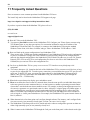
11 Frequently Asked Questions
50
11.1 SNMP Questions
51
11.2 Pager FAQs
52
12 Technical Support
53
1
1 Introduction
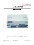
Fig. 1. The NEBs certified NetMediator T2S monitors alarms, pings network elements, and reports via pager or
email
The NetMediator T2S mediates sixty-four displays of TBOS alarm data to SNMP traps, enabling more
productive monitoring of microwave radios and other TBOS devices from contemporary SNMP-based network
operation centers.
With the NetMediator T2S, you don't have to rely on uninformative major/minor summary alarms to monitor
your radios. The NetMediator T2S fully captures TBOS data and converts it to detailed, highly informative
SNMP traps.
You'll be able to diagnose equipment problems with a high degree of accuracy — so you can send the right
technician with the right tools on the very first truck roll, reducing maintenance costs and windshield time.
And there's a lot more to the NetMediator T2S — like built-in terminal server functionality through four reach
through serial ports, so you can access, configure, and reboot on-site equipment through a remote Telnet session.
The NetMediator T2S also serves as a medium-capacity RTU, so you can take care of most of your monitoring
needs with just this one unit.
The NetMediator's 32 discrete inputs bring back the contact closure alarms you need to monitor in your facility,
saving you the expense of buying additional RTUs. Eight analog inputs monitor voltage or current and report
actual live values of temperatures and battery levels. Eight relays give you control over additional remote site
equipment.
Summary of Features
Mediation
•
•
•
•
more.
•
•
•
•
•
•
•
Four RS-232 ports accessible via TELNET.
Four RS-485 ports for TBOS.
TBOS alarm forwarding to SNMP managers.
32 discrete inputs for environmental alarms, equipment alarms, intrusion alarms, and much
DCP and SNMP relay commands forwarded to TBOS channel.
Monitor TBOS points from HTML interface.
32 "PING" alarms, a low level device check for IP aware equipment.
Eight analog alarms with four user defined thresholds set for each input.
Eight relay operated controls for remotely activating standby equipment, locking doors, or any
other event that can be triggered by a relay closure or opening.
PPP (dial-up network access).
Works seamlessly with DPS Masters T/Mon or IAM — DCP(x) version.
2
Physical
•
•
•
•
•
NEBs and CE certification available.
One rack unit tall and mounts in 23" rack.
Connectorized back panel (hinged wire-wrap back panel or connection to 66 blocks available).
LCD for descriptive display of alarms.
LED indications for alarm and communication status.
Access
•
•
•
•
•
Dial-up access available.
TELNET over LAN connection.
Local access with laptop through front panel craft port.
Web browser access for monitoring.
T2SEdit access via LAN, serial connection, or dial-up.
Upgradeability
•
Firmware updates are easily downloaded without affecting provisioning information, and can be
done either locally or remotely using NG Loader software.
Enhancements
•
The default port settings revert to 2400 baud 8,0,2 rts 30/10 when the port is selected for TBOS.
•
The TBOS port is no longer hard-coded: it is configurable on the fly and does not require a
reboot for changes to take place.
•
Each TBOS display is configurable for a specific device type.
•
New TBOS device types have been added.
•
Code space is expanded with the removal of BAC support.
•
Displays may be expanded with the enabling of expansion card support.
•
Maintain TBOS alarm summary count and device status.
•
Alternate path dial-up reporting of alarms to T/Mon.
3
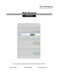
2 NetMediator T2S Functional Diagram
Internet Explorer
Ensure network and
device connectivity
by pinging network
elements (32 total)
Netscape
E-Mail Notification
Text Messages
T/MonXM
Telnet Reach Through
DCP(x)
LAN
Alt. Path
Dial-up
32 DiscreteAlarms
8 Analog Inputs
8 Controls
PPP
LAN Visibility of 8 Serial Devices
Pager
Dial-up access
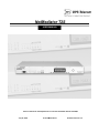
Fig. 2. The NetMediator T2S monitors all your remote site equipment and supports multiple visibility options.
4
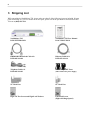
3 Shipping List
While unpacking the NetMediator T2S, please make sure that all of the following items are included. If some
parts are missing, or if you ever need to order new parts, please refer to the part numbers listed and call DPS
Telecom at (800) 622-3314.
NetMediator T2S
D-PK-NETMD-12024
NetMediator T2S User Manual
D-OC-UM067.28110
DB9M-DB9F Download Cable 6 ft.
D-PR-045-10A-04
Ethernet Cable 14 ft.
D-PR-923-10A-14
Telephone Cable 6 ft.
D-PR-045-10A-01
Two ¾-Amp GMT Fuses
23" Rack Ears
19" Rack Ears
Eight 3/8" Ear Screws and Eight Lock Washers
Four Rack Screws
(Eight with hinged panel)
(Three with sensor power supply)
5
Four Alternate Rack Screws
Power Screw Lug Barrier
(Eight with hinged panel)
(Two for dual power feed units)
Four Cable Ties
(Sixteen with hinged panel)
4 Optional Accessories
You can extend the capabilities of the NetMediator T2S through accessory units that provide greater discrete
alarm capacity, remote audiovisual alarm notification, visual surveillance of remote sites, and other options. If
you would like to order any of these accessories, or if you would like more information about them, call DPS
Telecom at (800) 622-3314.
NetGuardian Expansion (NetGuardian DX)
D-PC-293-10A-04
The NetGuardian Expansion provides an additional 48 discrete alarm points. Up to three NetGuardian
Expansions can be daisy-chained off one NetMediator T2S, providing a total of 176 alarm points.
General LCD Display (GLD)
D-PC-820-10A-04
The General LCD Display (GLD) is a small wall-mounted remote terminal for the NetMediator T2S. The LCD
display shows system status and alarm messages, and the built-in speaker gives an audible notice of alarms. Up
to 12 GLDs can be daisy-chained off the NetMediator T2S. (NetMediator T2S with optional RS-485 port
required.)
6
Hinged Wire-Wrap Back Panel
For 19" rack: D-PK-290-10A-19
For 23" rack: D-PK-290-10A-23
The hinged wire-wrap back panel provides wire-wrap connections for the NetMediator T2S's alarms and control
relays.
Pluggable Barrier Panel
D-AS-00140-10B
The pluggable barrier panel provides screw-lug barrier plug connections for the NetMediator T2S's alarms and
control relays.
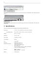
5 Specifications
These specifications refer to NetMediator T2S model D-PK-NETMD-12024.
Dimensions:
with Shipping Box:
1¾"H x 17"W x 12"D (4.45 cm x 43.18 cm x 30.48 cm)
6"H x 22"W x 12"D (15.24 cm x 55.88 cm x 30.48 cm)
Weight:
4 lbs. 3 oz. (1.9 kg)
Mounting:
19" or 23" rack
Power Input:
+24 VDC or –48 VDC
Current Draw:
200 mA
Fuse:
¾ amp GMT
Interfaces:
(as per current model)
4 DB9 RS-232 ports (1-4)
4 DB9 RS-485 ports (5-8)
1 RJ45 10BaseT Ethernet port
1 RJ11 POTS jack
2 50-pin connectors (discretes, controls, and analogs)
1 4-pin screw connector (analogs)
Protocols:
TBOS — in bound
SNMP and DCP(x) — out bound
Modem:
33.6K internal
7
Discrete Inputs:
32 (expandable)
Alarm Detection Speed:
User-defined (3 to 999 msec)
Analog Inputs:
8
Analog Input Range:
Control Outputs:
Maximum Voltage:
(–70 to 94 VDC or 4 to 20 mA)
8 Form C relay contacts
60 VDC/120 VAC
Maximum Current:
.3 Amp DC/.5 Amp AC
IP Address Ping Targets:
32
NVRAM Data Retention:
Indefinite (data will remain in NVRAM until memory is erased by user)
Visual Interface:
LCD display with descriptive text
16 bicolor LEDs
Audible Interface:
Alarm speaker
Operating Temperature:
32°–140° F (0°–60° C)
Operating Humidity:
0%–95% noncondensing
TBOS Devices Monitored:
MDR-4000E DS-3
MDR-6000
MDR-7000
MDR-8000 DS-1
MDR-8000 DS-3
Multiplex Lynx SC
JungleMux
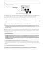
6 Hardware Installation Overview
Follow this order of steps when installing your NetMediator T2S.
1. Unpack the NetMediator T2S and check parts.
Please see the shipping list on pp. 3-4 to verify that all parts were included in your shipment.
2. Mount the NetMediator T2S.
The NetMediator T2S can be mounted in a 19" or 23" rack.
3. Connect power leads to the NetMediator T2S.
4. Connect communication lines to the NetMediator T2S.
The NetMediator T2S has two communication lines: a LAN connection (for Telnet and Web browser access) and
a standard telephone line (for dial-up access and paging capabilities).
5. Connect discrete alarm inputs.
8
6. Connect control outputs.
7. Connect analog alarm inputs.
8. Connect serial devices.
Up to eight serial devices can be connected to the NetMediator T2S's data ports. There are 4 DB9 RS-232 data
ports and 4 DB9 RS-485 data ports. These ports are also used for NetGuardian Expansion units and General
LCD Displays (see section 6.7, "Data Ports" for detailed information).
9. If necessary, set jumper positions on the circuit board and speaker.
You can change the operation of analog alarm inputs and control relays by resetting the jumpers on the
NetMediator T2S's circuit board — see section 6.10, "Jumper Options."
10. Install any NetMediator T2S accessories.
NetMediator T2S accessories include: NetGuardian expansion units, General LCD Displays, and a hinged
wire-wrap back panel and 66 blocks for alternate connectivity options. For full descriptions of NetMediator T2S
accessories see section 4, "Optional Accessories."
11. Connect to the NetMediator T2S.
You can connect to the NetMediator T2S either through the front panel craft port or through a network
connection.
12. Provision the NetMediator T2S.
The NetMediator T2S must be provisioned with log-on passwords, alarm descriptions, port parameters, ping
targets, control descriptions, and other system information. Basic provisioning and monitoring can be done in the
TTY interface — see section 9. All other provisioning must be done using the T2SEdit utility — see T2SEdit
User Manual for more information.
6.1
Tools Needed
To install the NetMediator T2S, you'll need the following tools:
Phillips No. 2 Screwdriver
Small Standard No. 2 Screwdriver
Wire Strippers/Cutter
wire-wrap Gun
(if hinged wire-wrap panel is used)
Punch Down Tool (if 66 blocks are used)
Computer with terminal software
or web browser
9
6.2
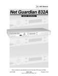
Mounting
Fig. 3. The NetMediator T2S can be flush or rear-mounted
The NetMediator T2S can be mounted in a 19" rack or a 23" rack by using the provided rack ears for each size.
Two rack ear locations are provided. Attach the appropriate rack ears in the flush-mount or rear-mount locations
shown in Figure 3.
Note: Rack ears can be rotated 90° for wall mounting or 180º for other mounting options not shown.
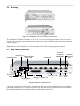
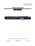
6.3
Back Panel Connections
Sensor Fuse
External Sensor
Grounding Post
Power Feed
Dual Power
Feeds
Data Ports
Connector
for optional
NetGuardian
Expansion
Discretes 1-24
1 Amp
Analogs 7-8
GMT Fuse
Analogs 1-6, Relays 1-8,
Temp Sensor
and Discretes 25-32
Connector
for optional
GLD
Telco Ethernet
Jack
Jack
Fig. 4. NetMediator T2S back panel
Connectors for power feeds, alarm inputs, control outputs, data ports, and communication lines are on the back
panel of the NetMediator T2S, as shown in Figure 4. The unit shown has some optional features not included in
the standard NetMediator T2S. Optional features are indicated by a dashed box.
10
6.4
Power Connection
Grounding post
Fig. 5. Power screw lug barrier plugs
The NetMediator T2S's power connections are convenient screw lug barrier plugs. If you require a backup power
source, optional dual power feeds are available. NetMediator T2S models with dual power feeds will
automatically draw from the backup power source if the primary power source becomes unavailable.
To connect the NetMediator T2S to a power source, follow these steps:
1. Remove the fuse from the rear panel of the NetMediator T2S and make sure that the power supply to the unit
is off.
2. Remove the screw lug barrier plug from the front panel of the NetMediator T2S.
3. Connect a –48 VDC line to the –48V terminal and a battery ground to the GND terminal of the screw lug.
Seat the barrier screws firmly, but be careful not to nick the bare wire. Repeat for power source B if you have
dual power inputs.
Note: Observe polarity when connecting battery leads. If using the –48 VDC red/black cables supplied with the
unit, connect the black lead to battery GND and the red lead to –BATT. Standard gauge is 20 AWG, but may
vary between 18 to 24 AWG.
4. Push the plug firmly back into its socket. Note that this connection is keyed and the plug must be properly
aligned within the socket.
5. For earth/frame grounding, connect a copper wire with a ring terminal to the grounding post located on the
back panel of the NetMediator T2S. DPS Telecom recommends wire of at least 14 gauge. Place the ring
terminal between the two nuts and secure the nuts on the grounding post. Connect the other end of the wire
to an earth/frame ground.
6. With the NetMediator T2S fuse still removed, turn on the power supply.
7. Connect the black common lead of a voltmeter to the GND terminal and the red lead to the –48V terminal.
The voltmeter should read between –43 and –53 VDC. If the reading is outside this range, check your power
supply.
8. Do not power the unit until all connections have been made.
9. Insert the fuse to power the NetMediator T2S. The power LED by the power feed will light green.
11
6.5
Communication Lines
Fig. 6 Telco and 10BaseT ports
Telco and 10BaseT Ethernet jacks are on the lower right corner of the NetMediator T2S's back panel, as shown
in Figure 6. Pinouts for the communication line connectors are shown in Figure 7.
RJ11 Phone Line Connection
RJ45 Ethernet Connection
4
3 Ring
2 Tip
1
8
7
6
5
4
3
2
1
Receive In– (RI–)
Receive In + (RI+)
Transmit Out– (TO–)
Transmit Out + (TO+)
Fig. 7. Pinouts for the RJ11 Telco jack and RJ45 10BaseT Ethernet connection
6.5.1
LAN Connection
The NetMediator T2S's LAN connection is used for many functions: Telnet or Ethernet access, provisioning,
firmware download, pinging network elements, and reporting alarms.
Connect a standard RJ45 Ethernet cable from your local area network (LAN) to the 10BaseT jack on the
NetMediator T2S back panel. (See Figures 6 and 7)
6.5.2
Phone Line Connection
The standard telephone connection is used for dial-up access and paging.
Connect a standard telephone cable from a POTS line to the RJ11 telco jack on the NetMediator T2S back panel.
(See Figures 6 and 7)
12
6.6
Alarm and Control Relay Connections
Fig. 8. Alarm and control relay connectors
Discrete alarms, analog alarms, and control relays are connected to the NetMediator T2S using the two 50-pin
connectors and the screw lug connectors on the back panel, shown in Figure 8. Pinouts for all three connections
are shown in Table A.
Table A. Alarm and relay connection pinouts
Note: The polarity of alarm point A is positive and alarm point B is negative. See Figure 9 for more alarm point
polarity information.
To simplify installation, DPS Telecom offers several optional accessories for alternative connections:
50-pin-to-open-end cables, a 50-pin-to-66 block, and a hinged back panel. Contact DPS Telecom at
1-800-622-3314 for more information.
13
6.6.1
Discrete Alarms
Dry Contact
Contact to Ground
NetMediator case
- Batt.
NetMediator case
AL 1B
AL 1B
AL 1A
AL 1A
- Batt.
Note: Make sure that grounds have a common reference
usually accomplished by tying grounds together.
Fig. 9. Discrete alarm points can connect as a dry contact or a contact to ground
The NetMediator T2S supports up to 32 discrete alarm inputs. Discrete alarms are typically used to monitor door
alarms, power outages, equipment failures, and other on/off conditions.
Discrete alarm points connected to the NetMediator T2S are single-lead signals referenced to ground. The B side
of each alarm point is internally wired to ground, so either a single wire bringing a contact to ground or a dry
closure with the second lead connected to the B side will be sensed as an alarm signal. (See Figure 9 for an alarm
connection diagram.)
Connect discrete alarms to the two 50-pin connectors on the back panel. Refer to Table A for discrete alarm
connection pinouts and the T2SEdit user manual for discrete alarm software configuration instructions.
6.6.2
Control Relays
The NetMediator T2S can control up to eight external devices. Controls can be used for starting or stopping
equipment, unlocking doors, and other functions.
Connect control relays to the 50-pin connector on the back panel labeled "Analog 1–6 Relay 1–8 Discretes 25–
32." Refer to Table A for control relay connection pinouts. Refer to the T2SEdit user manual for instructions on
setting the relay parameters and monitoring and operating relays.
The default setting for the relays is Normally Open (NO). The default setting can be changed to Normally Closed
(NC) by resetting the circuit board jumpers. For instructions on changing jumper settings, see Section 6.10,
"Jumper Settings."
6.6.3
Analog Alarms
The NetMediator T2S's eight analog inputs measure ranges of voltage or current inputs and can be used to
measure battery voltage, charging current, temperature, or other continuously variable conditions. The
measurement range of the analog channels is –94 to +94 VDC or 4 to 20 mA.
Connect analog inputs 1–6 to the 50-pin connector on the back panel labeled "Analog 1–6 Relay 1–8 Discretes
25–32." Connect analog inputs 7–8 to the screw lug connector labeled "Analog 7–8." Refer to Table A for analog
input pinouts. See the T2SEdit user manual for setting analog parameters.
14
The default setting for the analog channels is to measure voltage, but each channel can be separately set to
measure current by resetting the circuit board jumpers. For instructions on changing jumper settings, see Section
6.10, "Jumper Settings."
6.6.4
Integrated Temperature and Battery Sensor (Optional)
Temperature Sensor
Fig. 10. The integrated temperature sensor
The optional integrated temperature and battery sensor monitors the ambient temperature and the NetMediator
T2S's current draw. This option is available only if it was ordered with your NetMediator T2S.
The integrated temperature sensor measures a range of 32°–140°F (0°–60°) within an accuracy of +/– 1°.
No external connections are necessary for using the integrating sensors, but each integrated sensor takes the
place of an analog input. No other analog input can be connected to the input point used for the integrated
sensors. However, the analog inputs that are not used for the integrated sensors can still be used for external
analog inputs. Table B lists the connection options for the integrated temperature sensor. Note that these options
are set at the factory, based on the option ordered. These settings are not adjustable by the user.
Sensor Function
Temperature
Power Feed A
Power Feed B
Analog Input Options
Can be used on analog inputs 4 or 8
Can be used on analog inputs 5 or 7
Must be used on analog input 6
Table B. Integrated sensor connection options
6.7
Data Ports
PROXY CONNECTIONS
LAN
TELNET
Fig. 11. Concurrent proxy connections for multiple users to connect to different ports/devices via Telnet over LAN
The eight DB9 RS-232 data ports on the back panel of the NetMediator T2S can be used for several different
functions. Each port can function as a proxy connection to an external device, a craft port, a channel port, or a
TBOS polling port. See the T2SEdit user manual for data port configuration information and a description of
each function.
The NetMediator T2S can support simultaneous proxy connections via Telnet over LAN for up to eight users.
15
Some NetMediator T2S accessories must be connected to particular data ports. If you don't use these accessories,
the data ports are available for other uses. If you are using a NetGuardian Expansion unit, it must be connected to
Port 7. If you are using a General LCD Display (GLD) unit, it must be connected to Port 8 with a DB9 RS–485,
see Figure 13.
DB9 RS-232
RX
TX
GND
5 4 321
98 7 6
CTS
Pin # Signal
Description
1
2
3
4
5
6
7
8
9
Not connected
Transmit data
Receive data
Not connected
Ground
Not connected
Not connected
Clear to send
Not connected
TX
RX
GND
CTS
Fig. 12. Pinouts for DB9 RS-232 data ports
DB9 RS-485
RX+
TX+
5 4 321
98 7 6
RX-
TX-
Pin # Signal
Description
1
2
3
4
5
6
7
8
9
Transmit data +
Not connected
Not connected
Receive data +
Not connected
Transmit data Not connected
Not connected
Receive data -
TX+
RX+
TXRX-
Fig. 13. Pinouts for DB9 RS-485 data ports
16
6.8
66 Block (Optional)
Both of the 50–pin connectors on the back panel of the NetMediator T2S can be connected to the optional 66
block, 25 pair, block (part number D-PR-966-10A-00). See Figure 14 for pinout and color code information for
Discretes 1-24 and Figure 15 for pinouts and color code information for Discretes 24-32, Relays 1-8, and
Analogs 1-6.
Note: If connecting to a 25-pair split block, all connections should be made on the two pin columns closest to the
right-hand side of the block.
Fig. 14. 66 Block connections for Discretes 1–24
17
Fig. 15. 66 Block connections for Discretes 25–32, Relays 1–8, and Analogs 1–6
18
6.9
Hinged Wire-Wrap Back Panel (Optional)
Turn the plastic swivel
to the vertical position
to lock in place
Fig. 16. The hinged wire-wrap back panel is mounted on the mounting rack of the NetMediator T2S
To connect alarms and control relays to the optional hinged wire-wrap back panel, follow these steps:
1. Mount the hinged wire-wrap back panel on the mounting rack of the NetMediator T2S. (See Figure 16.)
2. Close the hinged back panel and lock in place by turning the black plastic locking swivel to the vertical
position.
3. Connect discrete alarms, analog alarms, and control relays to the two pin blocks. Figures 17 and 18 show the
pinouts for the wire-wrap back panel.
(Shown with point 5 wired)
Discretes 1 - 10
+6
+4
+2
+0
+8
10
1
RET
RET
Discretes 11 - 20
11
20
(Return 11 - 20)
RET
RET
Discretes 21 - 30
21
30
(Return 21 - 30)
RET
RET
(Return 1 - 10)
+4
+2
+6
+0
Fig. 17. Wire-wrap pinouts for Discretes 1–30
Analogs 1 - 8
Discretes 31 - 32
(Return 31 - 32)
Controls 1 - 8
+8
+0
+2
+4
+6
+8
+0
+2
+4
+6
+8
+
_
31
RET
N/O
COM
Fig. 18. Wire-wrap pinouts for Discretes 31–32, Analogs 1–8, and Controls 1–8
19
6.9.1
Lexan Wire-Wrap Cover
Spacer
Lexan panel
Lexan panel bracket
Securing screw
Fig. 19. Lexan panel assembly
To attach the Lexan cover to the hinged wire-wrap panel, follow these steps:
1. Attach communication lines to the wire-wrap pins before connecting the Lexan cover.
2. Attach the Lexan cover to the mounting clips and connect to the hinged panel — see Figure 19.
6.10 Jumper Options
J41
J42
CTRL 1–8
J51
J9
J15, J16, J18, J21, J23, J24
(underneath the daugher board)
J44
Speaker
Fig. 20. Adjustable jumpers on the NetMediator T2S circuit board
You can change the settings for analog alarm inputs by resetting the jumpers on the NetMediator T2S's circuit
board. To open the unit and expose the circuit board, remove the screws from the top of the NetMediator T2S.
Lift the top cover off. Figure 20 shows the circuit board and the location of the adjustable jumpers.
20
Jumper installed for current
Current
+
Analog
Channel
Input
250 Ohm
Shunt
-
4 to 20 ma
Current Source
Transducer
Jumper removed for voltage
Voltage
+
Analog
Channel
Input
Voltage Source
Transducer
Unjumpered/Open Position
Jumpered/Closed Position
-
Fig. 21. Jumper settings for analog alarm inputs and control relays
By default, all the adjustable jumpers are open, except for the speaker jumper. For analog alarm input jumpers,
the open position corresponds to voltage input, and the closed position corresponds to current input. For control
relay jumpers, the open position corresponds to normally open operation, and the closed position corresponds to
normally closed operation — see Figure 21. See Table C for default jumper settings and descriptions.
Note: Default settings may be different if you ordered a special configuration NetMediator T2S.
Jumper
J9
J15
J16
J18
J20
J21
J22
J24
J23
J41
J42
J44
J51
CTRL 1
CTRL 2
CTRL 3
CTRL 4
CTRL 5
CTRL 6
CTRL 7
CTRL 8
SPKR
Description
Factory Use Only
Analog 1
Analog 2
Analog 3
Analog 4
Analog 5
Analog 6
Analog 7
Analog 8
Factory Use Only
Factory Use Only
Factory Use Only
Factory Use Only
Control Relay 1
Control Relay 2
Control Relay 3
Control Relay 4
Control Relay 5
Control Relay 6
Control Relay 7
Control Relay 8
Speaker
Table C. Jumper descriptions and settings
* = Default position.
Open
N/O*
Voltage*
Voltage*
Voltage*
Voltage*
Voltage*
Voltage*
Voltage*
Voltage*
N/O*
N/O*
N/O*
N/O*
N/O*
N/O*
N/O*
N/O*
N/O*
N/O*
N/O*
N/O*
----
Closed
---Current
Current
Current
Current
Current
Current
Current
Current
------------------------------------N/C*
21
7 Front Panel Controls and Displays
LCD Display and Menu
Fig. 22. The NetMediator T2S LCD display
The front panel LCD displays the current alarm and control status. It also provides an option menu for
controlling the NetMediator T2S's basic functions.
Using the LCD display menu
The four buttons surrounding the front panel LCD display are used to access the LCD display menu. Press the
MENU button To access the menu. To scroll the menu, use the + and – buttons. To select a menu command,
press the SEL button.
Standard Prompt
When no menu item is selected, the LCD panel will display the firmware version and the standard prompt, "Press
MENU for front panel operations."
Controlling Display Speed
The scroll speed can be temporarily increased by pressing and holding the + button while the message is active.
7.1
Alarm and Control Status Messages
The LCD panel will display the following messages to indicate alarm and control status:
Discrete Alarms: If there are any standing discrete alarms, the display will read "Discrete Alarms:", followed by
the user-defined descriptions of the standing alarm points.
Relays: If there are any latched relays, the display will read "Relays:", followed by the user-defined descriptions
of the latched relays.
Ping Alarms: If any ping targets have failed to respond within the specified time, the display will read "Ping
Alarms:", followed by the user-defined descriptions of the ping targets.
Analogs: If any analog channels have crossed a threshold value, the display will read "Analogs", followed by a
status report for each analog channel that has crossed a threshold. The status report consists of the user-defined
description of the analog channel, the channel's last voltage reading, and a letter indicating which threshold the
channel has crossed.
The letter codes represent the following thresholds:
Major Over: a capital "O"
Minor Over: a lower-case "o"
22
Minor Under: a lower-case "u"
Major Under: a capital "U"
Note: There is also an option to always show analog values on the LCD screen. See the T2SEdit user manual
(System Settings) for further information.
7.2
Sound Controls
The LCD menu option "Sound off" will suppress all sounds for a 10-, 20- or 30-minute period. Select 0 to cancel
the suppression. The alarm will sound for the time set in the provisioning information — see T2SEdit user
manual.
The NetMediator T2S's audible alarm sounds under two conditions:
If there is an Ethernet link failure, the NetMediator T2S will emit a high-low warbling tone.
If there is a reportable alarm, the NetMediator T2S will emit an intermittent beep.
An alarm sound can be turned off by pressing any front panel button. Any reporting alarm sound will continue to
its normal end even when a subsequent alarm is detected. Stopping the sound by pressing a front panel button
allows the next alarm, if any, to sound.
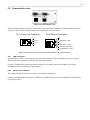
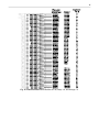
7.3
Front Panel LEDs
Fig. 23. Front panel LEDs
The front panel LEDs display alarm and communication status. Table D shows the meaning of the LED display
messages.
LED
Status
Flashing Red
Solid Red
ALM
Flashing Red
CFG
Flashing Green
LNK
LAN, CRF, MDM, DATA 1 – 8
Green
Red
Flashing Green
Flashing Red
Table D. LED status messages
Description
New alarm status
Standing alarm
acknowledged
NVRAM not verified
(download needed)
NVRAM verified, system
operational
Ethernet link OK
Ethernet link failure
Data transmit
Data receive
23
8 Preliminary Software Configuration
The NetMediator T2S must be provisioned with log-on passwords, alarm descriptions, port parameters, ping
targets, control descriptions, and other system information. Basic provisioning and monitoring can be done in the
TTY interface — see section 9. All other provisioning must be done using the T2SEdit utility — see T2SEdit
User Manual for more information.
Provision the NetMediator T2S locally through the craft port (see section 8.2) or remotely through a LAN
connection. To access the NetMediator T2S via LAN, make a temporary connection to the NetMediator T2S and
assign it an IP address on your network — see section 8.1.
8.1
Temporarily Changing Your Computer's IP Address and Subnet Mask
The factory default IP address is 192.168.1.100, and the default subnet mask is 255.255.0.0.
To temporarily adjust your computer's IP address and subnet mask to correspond to these settings, follow these
steps:
1. Access and write down your computer's IP address and subnet mask.
2. Temporarily change your computer's IP Address to 192.168.1.200 (In a Microsoft Windows setting, the IP
Address and Subnet Mask settings are typically found in the Control Panels - Network - TCP/IP window).
3. Temporarily change your computer's Subnet Mask to 255.255.0.0 (A reboot of your computer may be
necessary to initiate the changes).
4. You can now access the NetMediator T2S through the TTY or Ethernet interfaces, using the NetMediator
T2S's factory default IP address, 192.168.1.100. Assign the NetMediator T2S an IP address and subnet mask
on your network.
5. Change your computer's IP address and subnet mask back to their original settings.
Once the IP Address and Subnet Mask of your computer coincide with the NetMediator T2S's, you can access
the NetMediator T2S via a TELNET session or via web browser (See Web Browser user manual) by using the
NetMediator T2S's default IP Address of 192.168.1.100. After you have provisioned the NetMediator T2S with
the appropriate information, change your computer's IP Address and Subnet Mask back to their original settings.
Note: NetMediator Ethernet setting changes take effect only after a reboot.
24
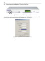
8.2
Connecting to the NetMediator T2S via the Craft Port
Fig. 24. The NetMediator T2S's front panel craft port
To make a local connection to the NetMediator T2S, use the provided DB9M-DB9F cable to connect the COM
port of your PC to the front panel craft port of the NetMediator T2S — see Figure 24.
Fig. 24. Port settings to connect to the NetMediator T2S
25
Open your terminal emulation software, Windows™ HyperTerminal for example, and set your computer's serial
port to match the NetMediator T2S's default data rate and word format settings by select the following COM port
options, as shown in Figure 24:
• Bits per second: 9600
• Data bits: 8
• Parity: None
• Stop bits: 1
• Flow control: None
Note: It is extremely important to set Flow Control to None. Flow control normally defaults to "Hardware" in
most terminal programs, this will not work correctly with the NetMediator T2S.
Assign the NetMediator T2S an IP address and subnet mask on your network. For instructions on assigning an IP
address, see section 8.1. Once a connection is established (sometimes accompanied by receipt of a hex byte),
type "DPSCFG" <Enter> to activate the TTY configuration menu.
8.3
LAN Connection and Ethernet Port Setup
You can connect to the NetMediator T2S using any standard TELNET client or web browser, but the Ethernet
port must first be configured. For TELNET, connect to the NetMediator T2S's IP address at port 2002 to access
the configurator menus after initial LAN/WAN setup. As an added security measure, TELNET sessions are
established at port 2002 — not the standard TELNET port 23. For web browser connections, enter the IP
address of the NetMediator T2S into the web browser's address bar and refer to the Web Browser Interface user
manual.
Initially, the NetMediator T2S must be provisioned with an appropriate IP address before you will be able to
connect via LAN/WAN using a TELNET client or a web browser. To connect via LAN, the minimum
configuration requires setup of the IP Address and Subnet Mask. Minimum WAN configuration requires that the
Default Gateway be set as well. Follow the instructions below to configure the NetMediator T2S's IP Address,
Subnet Mask, Default Gateway, Trap Address, SNMP Port Number, Proxy Base, and DCHP option.
1.
2.
3.
4.
5.
6.
7.
8.
9.
10.
11.
Connect to the NetMediator T2S via the craft port using the provided DB9M-DB9F cable
(D-PR-045-10A-04), see section 8.2 for connection settings.
Once a connection is established, the NetMediator T2S will respond with the Password: prompt.
Type "dpstelecom" (Factory default), then press <Enter>.
Note: DPS strongly recommends changing the default password.
The NetMediator T2S 's main menu will appear.
Note: Menu selection Hot Keys: The letters before a parentheses or enclosed in parentheses ( ) are hot
keys. Press the hot key to access that submenu. Pressing the <Esc> key will always bring you back to the
previous menu level. Entries are not case sensitive.
Type <C> to configure your unit.
Type <E> to edit your unit settings.
Type <E> to edit the Ethernet port.
Enter the unit address, subnet mask, and default gateway.
To save changes press <Esc> until prompted to save, choose Y)es.
Return to the C)onfig menu, go to the E)dit menu, then the S)ystems menu, and type <R> R)eboot. Type
<Y> to reboot. This will load the saved configuration.
Now you can connect over LAN using T2SEdit to complete the configuration, or configure the
26
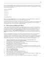
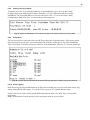
NetMediator T2S using the current connection.
Fig. 26. Configure the Ethernet port parameters
9 TTY Interface
Fig. 27. The TTY interface initial configuration screen
The TTY interface — one of the three available software interfaces for the NetMediator T2S — is primarily used
for basic configuring and provisioning the NetMediator T2S, but you can also use it to ping IP targets, view
system statistics, and data port activity. You must use the Windows-based T2SEdit utility for all other
provisioning — see T2SEdit user manual. You may also use the web browser interface to monitor your
NetMediator T2S alarm status — see Web Browser user manual.
To use the TTY interface with the NetMediator T2S, all you need is a computer with terminal emulation
software and a connection to the NetMediator T2S. This connection can be a direct connection to the
NetMediator T2S's front panel craft port (see section 8.1) or a remote connection via Telnet or dial-up (see
section 8.3). Some initial software configuration must be performed before you can use a remote connection to
the NetMediator T2S.
27
9.1
9.1.1
Unit Configuration
Connecting to the NetMediator T2S
In order for the NetMediator T2S to become configurable via TTY Interface or web browser, the IP address of
the NetMediator T2S must be in the same Subnet or on the same hub as your computer or network. The
NetMediator T2S has a default IP Address of 192.168.1.100 and a default Subnet Mask of 255.255.0.0.
Configuring the NetMediator T2S to be in the same Subnet as your computer or network can be achieved in one
of two ways:
1. By temporarily changing the IP Address and Subnet Mask of your computer in order to coincide with the
NetMediator T2S's default IP Address and Subnet Mask. Once you are in the same Subnet as the
NetMediator T2S's default settings, you can access the NetMediator T2S and change it's IP Address and
Subnet Mask in order to coincide with your computer or network settings (see section 8.1)
or
2. By accessing the NetMediator T2S via the front panel craft port and changing the IP Address and Subnet
Mask of the NetMediator T2S to match those of your computer or network (see section 8.2).
9.1.1.1 Remote Connection (Dial-up)
Set up a computer running TTY terminal emulation software, for example HyperTerminal, to dial the
NetMediator T2S's modem. When a connection is established (sometimes accompanied by receipt of a hex byte),
type DPSCFG, then press <Enter> to activate the TTY password prompt.
Note: If the system has been previously configured, it might be set for quiet login, which is part of the security
system. Enter your password without prompting until you are logged on.
9.2
Monitoring the NetMediator T2S
Connect a computer running VT-100 terminal emulation software to the craft port or connect via LAN using a
TELNET client (with VT-100 emulation) to port 2002 to reach the M)onitor menu selection. In TTY interface
you can monitor all alarms, ping information, relays, analogs, and system status.
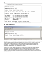
Fig. 28. The monitor menu allows status checking on all elements
9.2.1
Monitoring Base Alarms
The A)larm choice of the M)onitor menu allows you to view the status of the device connected to the discrete
input. Under the "Status" heading, the word "Alarm" will appear if an alarm has been activated and the word
"Clear" will appear if an alarm condition is not present.
28
Fig. 28. This example shows page two of the discrete alarms
9.2.2
Monitoring TBOS Ports
Select the T)BOS option by pressing <T> from the M)onitor menu to monitor the NetMediator T2S's defined
TBOS ports — see Figure 30. You can define up to eight ports as TBOS port types in the T2SEdit interface —
see T2SEdit user manual. You can also monitor the preset points of each device by entering the defined display
number after the prompt — see Figure 31.
Fig. 30. This example shows display 1–8 of Port 1
29
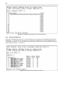
Fig. 30. Traps for each point can only be enabled in T2S Edit
Port types and Traps can only be enabled and configured in T2SEdit — refer to T2SEdit User Manual. There are
64 preset points for each device. To see a display map of the all the points refer to section 9.3.
9.2.3
Monitoring Ping Targets
Select P)ing targets from the M)onitor menu displays the status of all your ping targets. Under the "Status"
heading, the word "Alarm" will appear if an alarm has been activated and the word "Clear" will appear if an
alarm condition is not present. Press <P> to display your ping targets.
Fig. 32. The P)ing targets submenu allows you to change ping targets
30
9.2.4
Monitoring and Operating Relays (Controls)
The NetMediator T2S comes equipped with 8 relays, which can be used to control external devices. Select the
M)onitor > R)elays option by pressing <R> to monitor the status of your relays. The NetMediator T2S's 8 relays
are factory set to normally open (NO), but each or all of them can be changed to normally closed (NC) by
changing their respective jumper — see section 6.10.
Fig. 33. The NetMediator's eight relays can be operated from the M)enu > R)elays screen
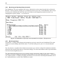
9.2.5
Monitoring Analogs
The M)onitor > a(N)logs option displays the descriptions previously entered for your NetMediator T2S's eight
analogs, the current reading, and the alarm status. To select the analog screen, press <N> from the M)onitor
menu.
The value shown is a snapshot of the channels measurement, not a real-time reading. Each adjustment should be
followed by the a(N)alog menu choice to refresh the readings. The alarm status indicates when a preset threshold
has been crossed, designated by an "x".
The eight analog measuring inputs, are set to measure voltage as the factory default. If your sensors output is
current, you will need to change the appropriate analog jumpers to the current measuring position — see section
6.10, "Jumper Options." To adjust your scaling reference for real world value monitoring and thresholds refer to
the "Analog Parameters" section of the T2SEdit user manual.
31
Fig. 34. Select M)onitor > a(N)logs to monitor your eight analog inputs
9.2.6
Monitoring System Alarms
Select M)onitor > A)larms by pressing <A> to monitor the NetMediator T2S's system alarms status. Figure 35
illustrates an example of the system alarms screen in the TTY interface. Under the "Status" heading, the word
"Alarm" will appear if an alarm has been activated and the word "Clear" will appear if an alarm condition is not
present.
Fig. 35. System alarms can be monitored from the M)onitor > S)ystem submenu by pressing the "S" key
9.2.7
Monitoring Data Port Activity
Monitor the status of the NetMediator T2S's eight data ports by pressing <O> from the M)onitor menu. The
M)onitor > p(O)rts option provides an ASCII description of your selected port. Press <a> to monitor "Transmit"
data, <b> for "Receive" data, <c> for "Transmit-HEX" data, or <d> for "Receive-HEX" data. See section 10.5,
"ASCII Conversion," for ASCII symbol conversion descriptions.
32
Fig. 36. Select M)onitor > p(O)rts to receive ASCII data from your NetMediator T2S's eight data ports
33
9.2.8
Viewing Live Ping Targets
To monitor any of the 32 pre-defined IP addresses on the NetMediator, press <P> from the C)onfig
(Configuration) menu. Inputting the IP address ID number (1-32) or a different IP address causes the
NetMediator T2S to ping that address in real time until you hit <Esc>. If you are not in the C)onfig
(Configuration) menu, press <Esc> to return to the previous menu level.
Fig. 37. Watch the NetMediator T2S continuously ping an IP address defined in the ping table
9.2.9
Proxy Menu
You can access devices connected to the seven DCE type data ports via the main menu > P)roxy menu option.
Proxy connections can take place via reach-through to the craft port, modem port or any of the NetMediator
T2S's 8 serial ports. To monitor your proxy connection to the NetMediator T2S press <P> from the main menu.
Fig. 38. Access devices connected to the seven DCE type data ports via the P)roxy menu selection
9.2.10 Event Logging
In the Event Log you can post and monitor up to 100 events including power up, base and system alarms, ping
alarms, analog alarms, and controls. To view the Event Log, press <E> from the M)onitor menu.
Posted events for the various alarms include both alarm and clear status. See Table. E for event log field
descriptions.
Note: All information in the Event Log will be erased upon reboot or a power failure.
34
Fig. 39. Monitor the last 100 events recorded by the NetMediator T2S in the Event Log window
Table E. Event Log field descriptions
9.2.11 Backing-Up NetMediator T2S Configuration Data via FTP
To back-up the NetMediator T2S's configuration data via FTP, follow the directions below:
1. Select "Run" from the "Start" menu on your computer.
2. Type "ftp" followed by the IP address of the NetMediator T2S you are backing up (e.g. "ftp 126.10.120.199").
3. After the connection is made press <Enter>.
4. Enter the password of the NetMediator T2S (no username necessary, default password is "dpstelecom") and
press <Enter>.
5. Type "binary" and press <Enter> (necessary for NetMediator T2S file transfer).
6. Type "lcd" and press <Enter> (this allows you to change the directory of your local machine).
7. Type "get" followed by the name you wish to define for the NetMediator T2S backup file. Add the extension
"nmd" to the file name (e.g. "get nmdbkup.nmd") and press <Enter>.
8. After back-up is finished, type "bye" and press <Enter> to exit.
Note: The back-up file name can have a maximum of eight characters before the file extension.
35
9.2.11.1 Reloading NetMediator T2S Configuration Data
To reload your NetMediator T2S configuration via FTP, use the following steps:
1.
Select "Run" from the "Start" menu on your computer.
2. Type "ftp" followed by the IP address of the NetMediator T2S to which you are reloading the backup
information (e.g."ftp 126.10.120.199").
3. After the connection is made press <Enter>.
4. Enter the password of the NetMediator T2S (no username necessary, default password is "dpstelecom") and
press <Enter>.
5. Type "binary" and press <Enter> (necessary for NetMediator T2S file transfer).
6. Type "lcd" and press <Enter> (this allows you to change the directory of your local machine).
7. Type "put" followed by the name you defined for the NetMediator T2S backup file and press <Enter> (e.g.
"put nmdbkup.nmd").
8. After reloading, type "bye" and press <Enter> to exit.
Note: Depending on setting changed by the database restore, you many need to reboot the unit.
36
9.2.12 Debug Input and Filter Options
Debug Input Options
ESC
B
T
U
R
X
?
a
A
c
C
d
D
Ee
E
f
F
G
H
H
i
k
l
L
m
M
o
O
p
P
q
Q
r
s
S
t
V
w
W
Exit Debug
Show BAC status points
Show task status
Show DUART information
Show network routing table
Clear debug enable bitmap. Turn all debug filters OFF
Display options
Debug Filter Options:
(1) Alarm toggle switch. Shows posting of alarm data
(2) Analog toggle switch. Shows TTY interface debug
(3) Config toggle switch. Shows TTY interface debug
(4) Control relay toggle switch. Shows relay operation
(5) DCP responder toggle switch. Shows DCP protocol
(6) Device toggle switch. Shows telnet and proxy info, and T2SEdit serial communication.
(7) Expansion poller toggle switch. Shows NGDdx polling
(8) ECU Interrogator toggle switch. Shows BAC processing
(9) FTP Command toggle switch. Shows command string parsing
(10) FTP Data toggle switch. Shows FTP Read / Write
(11) GLD poller toggle switch. Shows GLD polling
(12) HTML debug switch. Shows Web Browser processing
(13) HWACS debug switch. Shows hardware access operation
(14) PING toggle switch
(15) Socket toggle switch. Shows current dcu resources
(16) LED toggle switch. Shows current LED state
(17) LCD display toggle switch. Shows LCD control and text
(18) Modem toggle switch. Shows modem vectored initialization
(19) Undefined
(20) Osstart toggle switch. Miscellaneous application debug, including nvram read and write
operation, and event posting
(21) Undefined
(22) SPORT toggle switch. Port init debug and channeled port debug
(23) PPP toggle switch. Shows PPP functioning
(24) QAccess toggle switch. Reserved for future use
(25) Undefined
(26) Report toggle switch. Shows reporting event activity, including SNMP, pagers, email, etc. Also
shows PPP negotiation for NM-T2S client PPP mode.
(27) SNMP toggle switch. Reserved for future use
(28) STAK toggle switch. Shows network processing and IPA of arp requests. Also shows packets
discarded by Filter IPA.
(29) TERM toggle switch. Shows UDP/TCP port handling. The camera and network time (NTP)
jobs also use the TERM toggle switch
(30) Undefined
(31) HTTP toggle switch. Shows handling of web browser packets
(32) WEB toggle switch 2. Dump HTML text from web browser
37
10 Reference Information
10.1 Display Mapping
PORT DISPLAY
99
99
99
99
99
99
99
99
99
99
99
99
99
99
99
99
99
99
1
2
3–10
11
12
13
14
15
16
17
18–25
26–33
34–41
42–49
50–57
58–65
66–73
74–81
DESCRIPTION
SNMP TRAP #
SET
CLEAR
BASE ALARMS
8001–8064 9001–9064
PING TARGET ALARMS
8065–8128 9065–9128
ANALOG CHANNEL 1..8
8129–8640 9129–9640
RELAY/HOUSEKEEPING
8641–8704 9641–9704
EXPANSION 1 ALARMS
6001–6064 7001–7064
EXPANSION 1 RELAY/HOUSEKEEPING 6065–6128 7065–7128
EXPANSION 2 ALARMS
6129–6192 7129–7192
EXPANSION 2 RELAY/HOUSEKEEPING 6129–6192 7129-7162
EXPANSION 3 ALARMS
6256–6320 7256–7320
EXPANSION 3 RELAY/HOUSEKEEPING 6321–6384 7321–7384
TBOS PORT 1 DISPLAYS 1–8
10001–10512 11001–11512
TBOS PORT 2 DISPLAYS 1–8
12001–12512 13001–13512
TBOS PORT 3 DISPLAYS 1–8
14001–14512 15001–15512
TBOS PORT 4 DISPLAYS 1–8
16001–16512 17001–17512
TBOS PORT 5 DISPLAYS 1–8
18001–18512 19001–19512
TBOS PORT 6 DISPLAYS 1–8
20001–20512 21001–21512
TBOS PORT 7 DISPLAYS 1–8
22001–22512 23001–23512
TBOS PORT 8 DISPLAYS 1–8
24001–24512 25001–25512
Table A1. Display descriptions and SNMP Trap numbers for the NetMediator T2S
* The Trap number ranges shown correspond to the point range of each display. For example, the SNMP Trap
Set number for alarm 1 (in Display 1) is 8001, Set for alarm 2 is 8002, Set for alarm 3 is 8003, etc.
** The TRAP number descriptions for the Analog channels (1-8) are in the following order: minor under, minor
over, major under, and major over. For example, Analog channel 1, the Set number for minor under is 8129,
minor over is 8130, major under is 8131, and major over is 8132.
38
POINTS
DESCRIPTION
1
2
3
4
5
6
7
8
17
18
19
33
36
37
38
41
42
43
44
45
46
47
48
49
50
51
52
53
54
55
56
57
58
59
60
61
62
63
64
RELAYS
RELAYS
RELAYS
RELAYS
RELAYS
RELAYS
RELAYS
RELAYS
TIMED TICK
EXP. MODULE CALLOUT
NETWORK TIME SERVER
UNIT RESET
LOST PROVISIONING
DCP POLLER INACTIVE
LAN NOT ACTIVE
MODEM NOT RESPONDING
NO DIAL TONE
SNMP TRAP NOT SENT
PAGER QUE OVERFLOW
NOTIFICATION FAILED
CRAFT RCVQ FULL
MODEM RCVQ FULL
DATA 1 RCVQ FULL
DATA 2 RCVQ FULL
DATA 3 RCVQ FULL
DATA 4 RCVQ FULL
DATA 5 RCVQ FULL
DATA 6 RCVQ FULL
DATA 7 RCVQ FULL
DATA 8 RCVQ FULL
NETGUARDIAN DX 1 FAIL
NETGUARDIAN DX 2 FAIL
NETGUARDIAN DX 3 FAIL
GLD 1 FAIL
GLD 2 FAIL
GLD 3+ FAIL
CHAN. PORT TIMEOUT
CRAFT TIMEOUT
EVENT QUE FULL
SNMP TRAP #S
SET
CLEAR
8641
8642
8643
8644
8645
8646
8647
8648
8657
8658
8659
8673
8676
8677
8678
8681
8682
8683
8684
8685
8686
8687
8688
8689
8690
8691
8692
8693
8694
8695
8696
8697
8698
8699
8700
8701
8702
8703
8704
9641
9642
9643
9644
9645
9646
9647
9648
9657
9658
9659
9673
9676
9677
9678
9681
9682
9683
9684
9685
9686
9687
9688
9689
9690
9691
9692
9693
9694
9695
9696
9697
9698
9699
9700
9701
9702
9703
9704
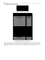
Table A2. Display 11 System Alarms point descriptions
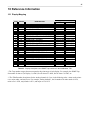
10.2 TBOS Devices Point Descriptions
Use the information in Tables A3-A9 for alarm point descriptions for specific TBOS devices.
39
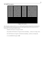
10.2.1 MDR-4000E DS-3 TBOS Point Description
PT #
MDR-4000E DS-3
PT #
MDR-4000E DS-3
1
2
3
4
5
6
7
8
9
10
11
12
13
14
15
16
17
18
19
20
21
22
23
24
25
26
27
28
29
30
31
32
A COMMON LOSS ALARM
A COMMON POWER SUPPLY
A RF TRANSMIT POWER ALARM
A PA POWER SUPPLY
A TRANSMIT LO LOCK
A ATPC HIGH POWER
A TRANSMIT DS3 FAIL
A DS1 INPUT ALARM
B COMMON LOSS ALARM
B COMMON POWER SUPPLY
B RF TRANSMIT POWER ALARM
B PA POWER SUPPLY
B TRANSMIT LO LOCK
B ATPC HIGH POWER
B TRANSMIT DS3 FAIL
B DS1 INPUT ALARM
A TRANSMIT ON LINE
A TRANSMIT SERVICE CHANNEL
ONLINE
A ATPC ACTIVE
A AIS DETECT
TRANSMIT OVERRIDE
SWITCH OFF NORMAL
COMMAND PATH FAIL
CONTROLLER ALARM
B TRANSMIT ON LINE
B TRANSMIT SERVICE CHANNEL ON
LINE
B ATPC ACTIVE
B AIS DETECT
WS DS1 LOOPBACK LINE 1
WS DS1 LOOPBACK LINE 2
33
34
35
36
37
38
39
40
41
42
43
44
45
46
47
48
49
50
51
52
53
54
55
56
57
58
59
60
61
62
63
64
A COMBINER ALARM
A CHANNEL FAIL
A RADIO FRAME LOSS
A EYE CLOSURE
A RECEIVER DS3 FAIL
A WS DS1 RECEIVER ALARM
NOT USED
A SYNC LOSS
B COMBINER ALARM
B CHANNEL FAIL
B RADIO FRAME LOSS
B EYE CLOSURE
B RECEIVER DS3 FAIL
B DS1 RECEIVER ALARM
NOT USED
B SYNC LOSS
RECEIVER ON LINE
A RECEIVER SERVICE CHANNEL
ONLINE
A WS DS1 ON LINE
A AIS DETECT
PCA LOCKOUT
A ATPC DOWN COMMAND
A ATPC UP COMMAND
RECEIVER OVERRIDE
B RECEIVER ON LINE
B RECEIVER SERVICE CHANNEL
ONLINE
B WS DS1 ON LINE
B AIS DETECT
PCA LOCKIN
B ATPC DOWN COMMAND
Table A3. MDR-4000E DS-3 TBOS point descriptions
Note: Alarm point 64 is set if a TBOS display is not polling.
40
10.2.2 MDR-6000 TBOS Point Descriptions
PT
#
1
2
3
6
7
MDR-6000
RELAY
A-SIDE COMMON LOSS ALARM
A-SIDE POWER SUPPLY
A-SIDE RF TRANSMIT POWER
A-SIDE ATPC HIGH POWER
A-SIDE DS1/E1 MUX ALARM
8
9
10
11
14
15
A-SIDE DS1/E1 INPUT ALARM
B-SIDE COMMON LOSS ALARM
B-SIDE POWER SUPPLY
B-SIDE RF TRANSMIT POWER
B-SIDE ATPC HIGH POWER
B-SIDE DS1/E1 MUX ALARM
16
17
19
20
21
22
B-SIDE DS1/E1 INPUT ALARM
A-SIDE TRANSMIT ON LINE
TRANSMIT OVERRIDE
A-SIDE ATPC ACTIVE
PREVIOUS SECTION
SWITCH OFF-NORMAL
23
COMMAND PATH FAIL
24
CONTROLLER ALARM
NO/NC
52
25
27
29
30
B-SIDE TRANSMIT ON LINE
B-SIDE ATPC ACTIVE
DS1/E1 LOOPBACK LINES 1-4
DS1/E1 LOOPBACK LINES 5-8
NO/NC
55
56
57
59
31
DS1/E1 LOOPBACK LINES 9-12
32
33
DS1/E1 LOOPBACK LINES 1316
A-SIDE PATH DISTORTION
MDR-6000
RELAY
NO/NC
NO/NC
NO/NC
NO/NC
NO/NC
PT
#
34
35
36
37
38
A-SIDE CHANNEL FAIL
A-SIDE RADIO FRAME LOSS
A-SIDE EYE CLOSURE
A-SIDE RADIO DADE
A-SIDE DS1/E1 DEMUX ALARM
NO/NC
NO/NC
NO/NC
NO/NC
NO/NC
NO/NC
NO/NC
NO/NC
39
40
41
42
43
44
A-SIDE AGC STATUS
A-SIDE SYNC LOSS
B-SIDE PATH DISTORTION
B-SIDE CHANNEL FAIL
B-SIDE RADIO FRAME LOSS
B-SIDE EYE CLOSURE
NO/NC
NO/NC
45
46
47
48
49
50
B-SIDE RADIO DADE
B-SIDE DS1/E1 DEMUX ALARM
B-SIDE AGC STATUS
B-SIDE SYNC LOSS
A-SIDE RECEIVE ON LINE
A-SIDE I/O ON LINE
51
RECEIVE OVERRIDE
A-SIDE ATPC DOWN
COMMAND
A-SIDE ATPC UP COMMAND
B-SIDE RECEIVE ON LINE
B-SIDE I/O ON LINE
I/O OVERRIDE
B-SIDE ATPC DOWN
COMMAND
NO/NC
NO/NC
62
63
B-SIDE ATPC UP COMMAND
64
COMM FAILURE
Table A4. MDR-6000 TBOS point descriptions
Note: Alarm point 64 is set if a TBOS display is not polling.
NO/NC
NO/NC
NO/NC
NO/NC
NO/NC
NO/NC
NO/NC
NO/NC
NO/NC
NO/NC
NO/NC
41
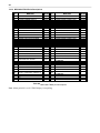
10.2.3 MDR-7000 TBOS Point Descriptions
PT #
1
2
3
4
5
6
7
8
9
10
11
12
13
14
15
16
17*
18
19
20
21
22
23
24
25*
26
28
29*
30*
31*
MDR-7000
PT #
MDR-7000
A-SIDE COMMON LOSS ALARM
32* DS1/E1 LOOPBACK LINES 13-16
A-SIDE IDU POWER SUPPLY
33
A-SIDE BER ALARM
A-SIDE RF TRANSMIT POWER
34
A-SIDE CARRIER UNLOCK
A-SIDE ODU POWER SUPPLY
35
A-SIDE RX RADIO FRAME LOSS
A-SIDE TRANSMIT BLOCK SYNC
36
A-SIDE TX RADIO FRAME LOSS
A-SIDE PROVISIONING ERROR
37
A-SIDE RADIO DADE
A-SIDE DS1/E1 MUX ALARM
38
A-SIDE DS1/E1 DEMUX ALARM
A-SIDE DS1/E1 INPUT ALARM
39
A-SIDE RECEIVE RSL ALARM
B-SIDE COMMON LOSS ALARM
40
A-SIDE SYNC LOSS
B-SIDE IDU POWER SUPPLY
41
B-SIDE BER ALARM
B-SIDE RF TRANSMIT POWER
42
B-SIDE CARRIER UNLOCK
B-SIDE ODU POWER SUPPLY
43
B-SIDE RX RADIO FRAME LOSS
B-SIDE TRANSMIT BLOCK SYNC
44
B-SIDE TX RADIO FRAME LOSS
B-SIDE PROVISIONING ERROR
45
B-SIDE RADIO DADE
B-SIDE DS1/E1 MUX ALARM
46
B-SIDE DS1/E1 DEMUX ALARM
B-SIDE DS1/E1 INPUT ALARM
47
B-SIDE RECEIVE RSL ALARM
A-SIDE TRANSMIT ONLINE
48
B-SIDE SYNC LOSS
A-SIDE IF SYNTHESIZER
49* A-SIDE RECEIVE ONLINE
TRANSMIT OVERRIDE
50
A-SIDE SUPERVISORY ALARM
A-SIDE ODU RF SYNTHESIZER
51
A-SIDE I/O ONLINE
PREVIOUS SECTION
52
RECEIVE OVERRIDE
SWITCH OFF-NORMAL
53
TEMPERATURE ALARM
COMMAND PATH FAIL
54
OPTION KEY ABSENT
CONTROLLER ALARM
55
DS3 ID MISMATCH
B-SIDE TRANSMIT ONLINE
57* B-SIDE RECEIVE ONLINE
B-SIDE IF SYNTHESIZER
58
B-SIDE SUPERVISORY ALARM
B-SIDE ODU RF SYNTHESIZER
59
B-SIDE I/O ONLINE
DS1/E1 LOOPBACK LINES 1-4
60
I/O OVERRIDE
DS1/E1 LOOPBACK LINES 5-8
61-63 NOT USED
DS1/E1 LOOPBACK LINES 9-12
64
COMM FAILURE
Table A5. MDR-7000 TBOS point descriptions
* TBOS Control Points (XMT Switch, RCV Swtich, I/O Switch, and Loopback Commands).
Note: Alarm point 64 is set if a TBOS display is not polling.
42
10.2.4 MDR-8000 DS-1 TBOS Point Descriptions
PT #
MDR-8000 DS-1
PT #
MDR-8000 DS-1
1
2
3
4
5
6
7
8
9
10
11
12
13
14
15
16
17
18
19
20
21
22
23
24
25
26
27
28
29
30
31
32
A COMMON LOSS ALARM
A POWER SUPPLY ALARM
A PA POWER ALARM
A TRANSMIT POWER ALARM
A PA POWER SUPPLY
A ATPC HIGH POWER
A WS DS1 TRANSMIT ALARM
A WS DS1 TRANSMIT LOSS OF INPUT
ALARM
B COMMON LOSS ALARM
B POWER SUPPLY ALARM
B PA POWER ALARM
B TRANSMIT POWER ALARM
B PA POWER SUPPLY
B ATPC HIGH POWER
B WS DS1 TRANSMIT ALARM
B WS DS1 TRA NSMIT LOSS OF INPUT
ALARM
A TRANSMIT ON LINE
A PA TEMPERATURE ALARM
TRANSMIT OVERRIDE
A ATPC OFF NORMAL
PREVIOUS SECTION ALARM
OFF NORMAL
RF COMMAND PATH ALARM
CONTROLLER POWER ON RESET
B TRANSMIT ON LINE
B PA TEMPERATURE ALARM
A ATPC OFF NORMAL
DAD E ALARM
DS1 LOOPBACK LINE 1 - 4
DS1 LOOPBACK LINE 5 - 8
33
34
35
36
37
38
39
40
41
42
43
44
45
46
47
48
49
50
51
52
53
54
55
56
57
58
59
60
61
62
63
64
A PATH DISTORTION
A CHANNEL FAIL
A RADIO FRAME LOSS
A EYE CLOSURE
A TERMINAL SYNC ALARM
A DS1 RECEIVER ALARM
A RECEIVE SIGNAL LEVEL ALARM
A REPEATER SYNC ALARM
B PATH DISTORTION
B CHANNEL FAIL
B RADIO FRAME LOSS
B EYE CLOSURE
B TERMINAL SYNC ALARM
B DS1 RECEIVER ALARM
B RECEIVE SIGNAL LEVEL ALARM
B REPEATER SYNC ALARM
A RECEIVER ON LINE
NOT USED
A I/O ON LINE
RECEIVER OVERRIDE
NOT USED
FAN ALARM
A ATPC LOCKED LOW
A ATPC LOCKED HIGH
B RECEIVER ONLINE
NOT USED
B I/O ON LINE
I/O OVERRIDE
NOT USED
B ATPC LOCKED LOW
B ATPC LOCKED HIGH
COMM FAILURE
Table A6. MDR-8000 DS-1 TBOS point descriptions
Note: Alarm point 64 is set if a TBOS display is not polling.
43
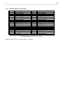
10.2.5 MDR-8000 DS-3 TBOS Point Descriptions
PT
#
MDR-8000 DS-3
PT #
1
2
3
4
5
6
A COMMON LOSS ALARM
A POWER SUPPLY ALARM
A PA POWER ALARM
A TRANSMIT POWER ALARM
A PA POWER SUPPLY
A ATPC HIGH POWER
33
34
35
36
37
38
7
A WS DS1 TRANSMIT ALARM
39
MDR-8000 DS-3
A COMBINER ALARM
A CHANNEL FAIL
A RADIO FRAME LOSS
A EYE CLOSURE
A RECEIVER DS3 FAIL
A WS DS1 RECEIVER ALARM
A RECEIVE SIGNAL LEVEL
ALARM
9
10
11
12
13
14
A WS DS1 TRANSMIT LOSS OF
INPUT
ALARM
B COMMON LOSS ALARM
B POWER SUPPLY ALARM
B PA POWER ALARM
B TRANSMIT POWER ALARM
B PA POWER SUPPLY
15
B ATPC HIGH POWER
47
16
B WS DS1 TRANSMIT ALARM
B WS DS1 TRANSMIT LOSS OF
INPUT
48
B COMBINER ALARM
B CHANNEL FAIL
B RADIO FRAME LOSS
B EYE CLOSURE
B RECEIVER DS3 FAIL
B WS DS1 RECEIVER
B RECEIVE SIGNAL LEVEL
ALARM
B REPEATER SYNC ALARM
49
A RECEIVER ON LINE
18
ALARM
50
19
20
21
22
23
24
25
26
A TRANSMIT ON LINE
A PA TEMPERATURE ALARM
TRANSMIT OVERRIDE
A ATPC OFF NORMAL
A TRANSMIT AIS DETECT
OFF NORMAL
RF COMMAND PATH ALARM
CONTROLLER POWER ON RESET
51
52
53
54
55
56
57
58
27
B TRANSMIT ON LINE
59
28
29
30
31
32
B PA TEMPERATURE ALARM
A ATPC OFF NORMAL
B TRANSMIT AIS DETECT
WS DS1 LOOPBACK LINE 1
WS DS1 LOOPBACK LINE 2
60
61
62
63
64
8
17
40
A REPEATER SYNC ALARM
41
42
43
44
45
46
A RECEIVER SERVICE
CHANNEL
ON LINE
A I/O ON LINE
RECEIVER OVERRIDE
A RECEIVER AIS DETECT
FAN ALARM
A ATPC LOCKED LOW
A ATPC LOCKED HIGH
B RECEIVER ONLINE
B RECEIVER SERVICE
CHANNEL
ON LINE
B I/O ON LINE
I/O OVERRIDE
B RECEIVER AIS DETECT
B ATPC LOCKED LOW
Table A7. MDR-8000 DS-3 TBOS point descriptions
Note: Alarm point 64 is set if a TBOS display is not polling.
44
10.2.6 Multiplex Lynx SC TBOS Point Descriptions
PT #
Multiplex Lynx SC
PT #
Multiplex Lynx SC
1
2
3
4
5
6
7
8
9
10
11
12
13
14
15
16
17
18
19
20
21
22
23
24
25
26
27
28
29
30
31
32
MODEL ID MSB
MODEL ID LSB+2
MODEL ID LSB+1
MODEL ID LSB
NOT USED
CHANNEL ID MSB
CHANNEL ID LSB
CHANNEL ID TX (HIGH/LOW)
RADIO FAIL
AIS OUT
FAN
RX SYNC
LOOPBACK ERROR
BER
FAR END
TELEMETRY DOWN
DATA LOSS CH 1
DATA LOSS CH 2
DATA LOSS CH 3
DATA LOSS CH 4
DATA LOSS DISABLE CH 1
DATA LOSS DISABLE CH 2
DATA LOSS DISABLE CH 3
DATA LOSS DISABLE CH 4
LOOPBACK SOURCE
LOOPBACK ERROR MODE
LOOPBACK CH1 ENABLE
LOOPBACK CH2 ENABLE
LOOPBACK CH3 ENABLE
LOOPBACK CH4 ENABLE
AIS DISABLED
BRIDGE DISABLED
33
34
35
36
37
38
39
40
41
42
43
44
45
46
47
48
49
50
51
52
53
54
55
56
57
58
59
60
61
62
63
64
LINE CODE CH1
LINE CODE CH2
LINE CODE CH3
LINE CODE CH4
FAR-END ADDRESS INVALID
FAR-END ADDRESS MSB
FAR-END ADDRESS LSB+1
FAR-END ADDRESS LSB
NEAR-END RSL MSB
NEAR-END RSL MSB-1
NEAR-END RSL MSB-2
NEAR-END RSL MSB-3
NEAR-END RSL MSB-4
NEAR-END RSL MSB-5
NEAR-END RSL MSB-6
NEAR-END RSL MSB-7
NEAR-END TX MSB
NEAR-END TX MSB-1
NEAR-END TX MSB-2
NEAR-END TX MSB-3
NEAR-END TX MSB-4
NEAR-END TX MSB-5
NEAR-END TX MSB-6
NEAR-END TX MSB-7
DUAL FAN FAIL
TX SYNC UNLOCK
RX SYNC UNLOCK
INPUT LINER DRIVER
DIGITAL HARDWARE
NOT USED
NOT USED
COMM FAILURE
Table A8. Multiplex Lynx SC TBOS point descriptions
Note: Alarm point 64 is set if a TBOS display is not polling.
45
10.2.7 JungleMux TBOS Point Description
PT #
1
2
3
4
5
6
7
8
10
13
14
15
16
32
JungleMux
PT #
NODE A MINOR
NODE A SYNC/L
NODE A MAJOR
NODE A POWER
NODE A CHAN/L
NODE A JMUX/L
NODE A SPE/L
NODE A AIS/L
NODE A SYNC/R
NODE A CHAN/R
NODE A JMUX/R
NODE A SPE/R
NODE A AIS/R
NOT USED
33
34
35
36
37
38
39
40
42
45
46
47
48
64
JungleMux
NODE B MINOR
NODE B SYNC/L
NODE B MAJOR
NODE B POWER
NODE B CHAN/L
NODE B JMUX/L
NODE B SPE/L
NODE B AIS/L
NODE B SYNC/R
NODE B CHAN/R
NODE B JMUX/R
NODE B SPE/R
NODE B AIS/R
COMM FAILURE
Table A9. JungleMux TBOS point descriptions
Note: Alarm point 64 is set if a TBOS display is not polling.
46
10.3 SNMP Manager Functions
The SNMP Manager allows the user to view alarm status, set date/time, issue controls, and perform a re-sync. The display
and tables below outline the MIB object identifiers. Table B1 begins with dpsRTU, however, the MIB object identifier tree
has several levels above it. The full English name is as follows:
root.iso.org.dod.internet.private.enterprises.dps-Inc.dpsAlarmControl.dpsRTU. Therefore, dpsRTU's full object identifier is
1.3.6.1.4.1.2682.1.2. Each level beyond dpsRTU adds another object identifying number. For example, the object identifier
of the Display portion of the Control Grid is 1.3.6.1.4.1.2682.1.2.3.3 because the object identifier of dpsRTU is
1.3.6.1.4.1.2682.1.2 + the Control Grid (.3) + the Display (.3).
dpsRTU
1.3.6.1.4.1.2682.1.2
_OV_vTraps
(.0)
Ident
(.1)
DisplayGrid
(.2)
ControlGrid
(.3)
DisplayEntry (.1)
See Table B1
See Table B2
Tbl. B1 (O.)_OV_Traps
points
_OV_vTraps
(1.3.6.1.4.1.2682.1.2.0)
PointSet (.20)
PointClr (.21)
SumPSet (.101)
SumPClr (.102)
ComFailed (.103)
ComRestored (.014)
P0001Clr (.20001) through
P0064Set (.10064)
See Table B3
NVRamGrid
(.4)
AlarmGrid
(.5)
NVRamSection (.1)
See Table B4
See Table B5
AlarmEntry (.1)
See Table B6
Ident
(1.3.6.1.4.1.2682.1.2.1)
Manufacturer (.1)
Model (.2)
Tbl. B3 (.2) DisplayGrid
points
DisplayEntry
(1.3.6.1.4.1.2682.1.2.2.1)
Port (.1)
Address (.2)
Firmware Version (.3)
Display (.3)
Tbl. B2 (.1) Identity points
DateTime (.4)
ResyncReq (.5)*
* Must be set to "1" to perform
the resync request which will
resend TRAPs for any standing
alarm.
DispDesc (.4)*
PntMap (.5)*
P0001Clr (.20001) through
P0064Clr (.20064)
Tbl. B4 (.3) ControlGrid
points
ControlGrid
(1.3.6.1.4.1.2682.1.2.3)
Port (.1)
Address (.2)
Display (.3)
Point (.4)
Action (.5)
Tbl. B5 (.4) NVRamSection
points
NVRamSection
(1.3.6.1.4.2682.1.2.4.1)
NVsNmbr (.1)
NvsData (.2)
NvsStatus (.3)
Tbl. B6 (.5) AlarmEntry
points
AlarmEntry
(1.3.6.4.1.2682.1.2.5.1)
APort (.1)
AAddress (.2)
ADisplay (.3)
APoint (.4)
APntDesc (.5)*
AState (.6)
* For specific point
descriptions, see Table B7.
Table B1. MIB object identifier tree descriptions
In Table B7, * "No data" indicates the alarm point is defined but there is no description entered, and ** "Undefined"
indicates that the alarm point is not used. Refer to sections 10.1 – 10.2.5 for descriptions of TBOS displays.
47
Disp 1
Disp 2
Disp 3
Disp 4
Disp 5
Disp 6
Disp 7
Disp 8
Disp 9
Disp 10
Disp 11
Disp 12
Disp 13
Disp 14
Disp 15
Disp 16
Disp 17
Disp 18
Disp 26
Disp 34
Disp 42
Disp 50
Disp 58
Disp 66
Disp 74
Description
No data*
Undefined**
No data*
Undefined**
Analog 1
Undefined**
Analog 2
Undefined**
Analog 3
Undefined**
Analog 4
Undefined**
Analog 5
Undefined**
Analog 6
Undefined**
Analog 7
Undefined**
Analog 8
Undefined**
No data*
Undefined**
Power up
Undefined**
Lost
DCP poll inactive
LAN not active
Undefined**
Modem not
No dial-tone
SNMP trap not
Pager Que
Notification
Craft RCVQ full
Modem RCVQ
Data 1-8 RCVQ
NGdx 1-3 fail
GLD 1-3 fail
CHAN timeout
CRFT timeout
Expansion1 Alarms
Expansion 1 Relay/Housekeeping
Expansion 2 Alarms
Expansion 2 Relay/Housekeeping
Expansion 3 Alarms
Expansion Relays/Housekeeping
TBOS PORT 1 DISPLAYS 1-8
TBOS PORT 2 DISPLAYS 1-8
TBOS PORT 3 DISPLAYS 1-8
TBOS PORT 4 DISPLAYS 1-8
TBOS PORT 5 DISPLAYS 1-8
TBOS PORT 6 DISPLAYS 1-8
TBOS PORT 7 DISPLAYS 1-8
TBOS PORT 8 DISPLAYS 1-8
Port
99
99
99
99
99
99
99
99
99
99
99
99
99
99
99
99
99
99
99
99
99
99
99
99
99
99
99
99
99
99
99
99
99
99
99
99
99
99
99
99
99
99
99
99
99
99
99
99
99
99
99
99
99
99
Address
1
1
1
1
1
1
1
1
1
1
1
1
1
1
1
1
1
1
1
1
1
1
1
1
1
1
1
1
1
1
1
1
1
1
1
1
1
1
1
1
1
1
1
1
1
1
1
1
1
1
1
1
1
1
Table B2. Alarm Point Descriptions
Display
1
1
2
2
3
3
4
4
5
5
6
6
7
7
8
8
9
9
10
10
11
11
11
11
11
11
11
11
11
11
11
11
11
11
11
11
11
11
11
11
12
13
14
15
16
17
18
19
20
21
22
23
24
25
Points
1-32
33-64
1-32
33-64
1-4
5-64
1-4
5-64
1-4
5-64
1-4
5-64
1-4
5-64
1-4
5-64
1-4
5-64
1-4
5-64
1-8
9-32
33
34-35
36
37
38
39-40
41
42
43
44
45
46
47
48-55
56-58
59-61
62
63
1-64
1-64
1-64
1-64
1-64
1-64
1-64
1-64
1-64
1-64
1-64
1-64
1-64
1-64
48
10.4 SNMP Granular Trap Packets
UDP Header
Description
1238
162
303
0xBAB0
Source port
Destination port
Length
Checksum
Table C1. UDP Headers and descriptions
SNMP Header
Description
0
Version
public
Request
Trap
Request
1.3.6.1.4.1.2682.1.2
Enterprise
126.10.230.181
Agent address
Enterprise Specific
Generic Trap
8001
Specific Trap
617077
Time stamp
1.3.7.1.2.1.1.1.0
Object
NetMediator T2S v.1.0F
Value
1.3.6.1.2.1.1.6.0
Object
1-800-622-3314
Value
1.3.6.1.4.1.2682.1.2.4.1.0
Object
01-02-1995 05:08:27.760
Value
1.3.6.1.4.1.2682.1.2.5.1.1.99.1.1.1
Object
99
Value
1.3.6.1.4.1.2682.1.2.5.1.2.99.1.1.1
Object
1
Value
1.3.6.1.4.1.2682.1.2.5.1.3.99.1.1.1
Object
1
Value
1.3.6.1.4.1.2682.1.2.5.1.4.99.1.1.1
Object
1
Value
1.3.6.1.4.1.2682.1.2.5.1.5.99.1.1.1
Object
Rectifier Failure
Value
1.3.6.1.4.1.2682.1.2.5.1.6.99.1.1.1
Object
Alarm
Value
Table C2. SNMP headers and descriptions
Tables C1 and C2 provide a list of the information contained in the SNMP Trap packets sent by the NetMediator
T2S. SNMP Trap managers can use 1 of 2 methods to get alarm information: 1. Granular traps (not necessary to
define point descriptions for the NetMediator T2S) or 2. The SNMP manager reads the description from the
Trap.
49
10.5 ASCII Conversion
Abbreviation
Description
Abbreviation
Description
NUL
SOH
STX
ETX
EOT
ENQ
ACK
BEL
BS
HT
LF
VT
FF
CR
SO
SI
Null
Start of Heading
Start of Text
End of Text
End of Transmission
Enquiry
Acknowledge
Bell
Backspace
Horizontal Tabulation
Line Feed
Vertical Tabulation
Form Feed
Carriage Return
Shift Out
Shift In
DLE
DC
NAK
SYN
ETB
CAN
EM
SUB
ESC
FS
GS
RS
US
SP
DEL
BRK
Data Link Escape
Device Control
Negative Acknowledge
Synchronous Idle
End of Transmission Block
Cancel
End of Medium
Substitute
Escape
File Separator
Group Separator
Record Separator
Unit Separator
Space (blank)
Delete
Break Received
Table D1. ASCII symbols
The information contained in Table D is a list of ASCII symbols and their meanings. Refer to the bulleted list
below to interpret the ASCII data transmitted or received through the data ports. Port transmit and receive
activity can be viewed from the Ethernet interface.
• Printable ASCII characters will appear as ASCII.
• Non-printable ASCII characters will appear as labels surrounded by { } brackets, for example {NUL}.
• Non-ASCII characters will appear as hexadecimal surrounded by [ ] brackets, for example [IF].
• A received BREAK will appear as BRK.
50
11 Frequently Asked Questions
Here are answers to some common questions from NetMediator T2S users.
The latest FAQs can be found on the NetMediator T2S support web page:
http://www.dpstele.com/support/techfaqs/netmediator.html
If you have a question about the NetMediator T2S, please call us at
(559) 454-1600
or e-mail us at
[email protected]
Q. How do I Telnet to the NetMediator T2S?
A. You must use Port 2002 to connect to the NetMediator T2S. Configure your Telnet client to connect using
TCP/IP (not Telnet, or any other port options). For connection information, enter the IP address of the
NetMediator T2S and Port 2002. For example, to connect to the NetMediator T2S using the standard
Windows Telnet client, click Start, click Run, and type Telnet <NetMediator T2S IP address > 2002.
Q. How can I back up the current configuration of my NetMediator T2S?
A. There are two ways. T2SEdit can read the configuration of your NetMediator T2S and save the configuration
to your PC's hard disk or a floppy disk. With T2SEdit you can also make changes to the configuration file
and write the changed configuration to the NetMediator T2S NVRAM. The other way is to use File Transfer
Protocol (FTP). You can use FTP to read configuration files from or write files to the NetMediator T2S
NVRAM, but you can't use FTP to edit configuration files.
Q. Can I use my NetMediator T2S as a proxy server to access TTY interfaces on my third-party serial
equipment?
A. You can use data ports 1–8, located on the back of the NetMediator T2S, to connect to serial devices, as long
as your devices support RS-232. To make a proxy connection, you must define the correct TCP port for each
serial port. To define TCP ports, you must first connect directly to the NetMediator T2S through its IP
address. Once you have connected to the NetMediator T2S, you can define the TCP ports through the
NetMediator T2S — T2SEdit utility.
Q. What do the terms alarm point, display, port, and address mean?
A. These terms define the exact location of a network alarm, from the most specific (an individual alarm point)
to the most general (an entire monitored device). An alarm point is a number representing an actual contact
closure that is activated when an alarm condition occurs. For example, an alarm point might represent a low
oil sensor in a generator or a open/closed sensor in a door. A display is a logical group of 64 alarm points. A
port is traditionally the actual physical serial port through which the monitoring device collects data. The
address is a number representing the monitored device. The terms port and address have been extended to
refer to logical, or virtual, ports and addresses. For example, the NetMediator T2S reports internal alarms on
Port 99, address 1.
Q. What characteristics of an alarm point can I configure through software? For instance, can I configure Point
4 to sense an active-low (normally closed) signal, or Point 5 to sense a level or edge?
A. The NetMediator T2S alarm points are level sensed and can be software-configured to generate an alarm on
either a high (normally open) or low (normally closed) level.
Q. When I connect to the NetMediator T2S through the Craft port on the front panel it either doesn't work right
51
or it doesn't work at all. What's going on?
A. Make sure your using the right COM port settings. The standard settings for the Craft port are 9600 baud, 8
bits, no parity, and 1 stop bit. Flow control must be set to none. Flow control normally defaults to hardware
in most terminal programs, and this will not work correctly with the NetMediator T2S.
Q. I just changed the port settings for one of my data ports, but the changes did not seem to take effect even
after I wrote the NVRAM.
A. In order for data port and Craft port changes (including changes to the baud rate and word format) to take
effect, the NetMediator T2S must be rebooted. When you make changes, remember to write them to the
NetMediator T2S NVRAM so they will be saved when the unit is rebooted.
Q. How do I get my NetMediator T2S on the network?
A. Before the NetMediator T2S will work on your LAN, the unit address (IP address), the subnet mask, and the
default gateway must be set. A sample configuration could look like this:
unit address: 192.168.1.100
subnet mask: 255.255.255.0
Default Gateway: 192.168.1.1
Always remember to save your changes by writing to the NVRAM. Any modifications of the NetMediator
T2S IP configuration will also require a reboot.
Q. I'm using HyperTerminal to connect to the NetMediator T2S through the Craft port, but the unit won't accept
input when I get to the first level menu.
A. Make sure you turn off all handshaking in HyperTerminal.
Q. I can't change the Craft port baud rate.
A. Once you select a higher baud rate, you must set your terminal emulation to that new baud rate and enter the
DPSCFG and press Enter. The Craft port interprets a break key as an override to 9600 baud. At slower baud
rates, normal keys can appear as a break.
Q. The LAN line LED is green on my NetMediator T2S, but I can't poll it from my T/MonXM master.
A. Some routers will not forward to an IP address until the MAC address has been registered with the router.
You need to enter the IP address of your T/MonXM system or your gateway in the ping table.
Q. How will I know if the TBOS ports are polling correctly?
A. The front panel LEDs will flash red and green.
11.1 SNMP Questions
Q. Which version of SNMP is supported by the SNMP agent on the NetMediator T2S?
A. SNMP v1.
Q. How do I configure the NetMediator T2S to send traps to an SNMP manager? Is there a separate MIB for the
NetMediator T2S? How many SNMP managers can the agent send traps to? And how do I set the IP address
of the SNMP manager and the community string to be used when sending traps?
A. The NetMediator T2S begins sending traps as soon as the SNMP managers are defined. The NetMediator
T2S MIB is included on the NetMediator T2S Resource CD. The MIB should be compiled on your SNMP
manager. (Note: MIB versions may change in the future.) The unit supports a main SNMP manager, which is
configured by entering its IP address in the trap address field of Ethernet Port Setup. You can also configure
up to eight secondary SNMP managers, which are configured by selecting the secondary SNMP managers as
pager recipients. Community strings are configured globally for all SNMP managers. To configure the
community strings configure them in the T2SEdit utility.
Q. Does the NetMediator T2S support MIB-2 and/or any other standard MIBs?
A. The NetMediator T2S supports the bulk of MIB-2.
52
Q. Does the NetMediator T2S SNMP agent support both NetMediator T2S and T/MonXM variables?
A. The NetMediator T2S SNMP agent manages an embedded MIB that supports only the NetMediator T2S
RTU variables. The T/MonXM variables are included in the distributed MIB only to provide SNMP
managers with a single MIB for all DPS Telecom products.
Q. How many traps are triggered when a single point is set or cleared? The MIB defines traps like major alarm
set/cleared, RTU point set, and a lot of granular traps, which could imply that more than one trap is sent
when a change of state occurs on one point.
A. Generally, a single change of state generates a single trap, but there are two exception to this rule. Exception
1: the first alarm in an all clear condition generates an additional summary point set trap. Exception 2: the
final clear alarm that triggers an all clear condition generates an additional summary point clear trap.
Q. What does point map mean?
A. A point map is a single MIB leaf that presents the current status of a 64-alarm-point display in an
ASCII-readable form, where a "."represents a clear and an "x" represents an alarm.
Q. The NetMediator T2S manual talks about two control relay outputs. How do I control these from my SNMP
manager?
A. The control relays are operated by issuing the appropriate set commands, which are contained in the DPS
Telecom MIB. For more information about the set commands, see Reference Information, Display Mapping,
in any of the NetMediator T2S software configuration guides.
Q. How can I associate descriptive information with a point for the RTU granular traps?
A. The NetMediator T2S alarm point descriptions are individually defined using the T2SEdit utility.
Q. My SNMP traps aren't getting through. What should I try?
A. Try these three steps:
1. Make sure that the trap address (IP address of the SNMP manager) is defined. (If you changed the trap
address, make sure you saved the change to NVRAM and rebooted.)
2. Make sure all alarm points are configured to send SNMP traps.
3. Make sure the NetMediator T2S and the SNMP manager are both on the network. Use the NetMediator
T2S ping command to ping the SNMP manager.
11.2 Pager FAQs
Q. Why won't my alpha pager work?
A. To configure the NetMediator T2S to send alarm notifications to an alpha pager, enter the data phone
number for your pager in the Phone Number field. This phone number should connect to your pager services
modem. Then enter the PIN for your pager in the PIN/Rcpt/Port field. You don't need to enter anything in
any of the other fields. If you still don't receive pages, try setting the Dial Modem Init string to ATS37=9.
This will limit the NetMediator T2S connection speed.
Q. Numeric pages don't come in or are cut off in the middle of the message. What's wrong?
A. You need to set a delay between the time the NetMediator T2S dials your pager number and the time the
NetMediator T2S begins sending the page message. You can set the delay in the Pager Number field, where
you enter your pager number. First enter the pager number, then enter some commas directly after the
number. Each comma represents a two-second delay. So, for example, if you wanted an eight-second delay,
you would enter 555-1212,,,, in the Pager Number field.
Q. What do I need to do to set up e-mail notifications?
A. You need to assign the NetMediator T2S an e-mail address and list the addresses of e-mail recipients. Let's
explain some terminology. An e-mail address consists of two parts, the user name (everything before the @
sign) and the domain (everything
53
after the @ sign). To assign the NetMediator T2S an e-mail address, enter your email addresses in the
T2SEdit utility. Enter the NetMediator T2S user name in the Name field (it can't include any spaces) and the
domain in the Location field. For example, if the system configuration reads:
Name: NetMediatorT2S
Location: proactive.com
Then e-mail notifications from the NetMediator T2S will be sent from the address
[email protected].
The next step is to list the e-mail recipients. Choose Pagers from the Edit menu. For each e-mail recipient,
enter his or her e-mail domain in the Phone/Domain field and his or her user name in the PIN/Rcpt/Port field.
You must also enter the IP address of an SNMP server in the IPA field.
12 Technical Support
DPS Telecom products are backed by our courteous, friendly Technical Support representatives, who will give
you the best in fast and accurate client service. To help us help you better, please take the following steps before
calling Technical Support:
1. Check the DPS Telecom website.
You will find answers to many common questions on the DPS Telecom website, at http://www.dpstele.com
. Look here first for a fast solution to your problem.
2. Prepare relevant information.
Having important information about your DPS Telecom product in hand when you call will greatly reduce the
time it takes to answer your questions. If you do not have all of the information when you call, our Technical
Support representatives can assist you in gathering it. Please write the information down for easy access.
Please have your user manual and hardware serial number ready.
3. Have access to troubled equipment.
Please be at or near your equipment when you call DPS Telecom Technical Support. This will help us solve
your problem more efficiently.
4. Call during Client Support hours.
Customer support hours are Monday through Friday, from 7 A.M. to 6 P.M., Pacific time. The DPS Telecom
Technical Support phone number is (559) 454-1600.
Emergency Assistance: Emergency assistance is available 24 hours a day, 7 days a week. For emergency
assistance after hours, allow the phone to ring until it is answered with a paging message. An on-call technical
support representative will return your call as soon as possible.
54
Warranty
DPS Telecom warrants, to the original purchaser only, that its products a) substantially conform to DPS' published
specifications and b) are substantially free from defects in material and workmanship. This warranty expires two years from
the date of product delivery with respect to hardware and ninety days from the date of product delivery with respect to
software. If the purchaser discovers within these periods a failure of the product to substantially conform to the specifications
or that the product is not substantially free from defects in material and workmanship, the purchaser must promply notify
DPS. Within reasonable time after notification, DPS will endeavor to correct any substantial non-conformance with the
specifications or substantial defects in material and workmanship, with new or used replacement parts. All warranty service
will be performed at the company's office in Fresno, California, at no charge to the purchaser, other than the cost of shipping
to and from DPS, which shall be the responsiblity of the purchaser. If DPS is unable to repair the product to conform to the
warranty, DPS will provide at its option one of the following: a replacement product or a refund of the purchase price for the
non-conforming product. These remedies are the purchaser's only remedies for breach of warranty. Prior to initial use the
purchaser shall have determined the suitability of the product for its intended use. DPS does not warrant a) any product,
components or parts not manufactured by DPS, b) defects caused by the purchaser's failure to provide a suitable installation
environment for the product, c) damage caused by use of the product for purposes other than those for which it was designed,
d) damage caused by disasters such as fire, flood, wind or lightning unless and to the extent that the product specification
provides for resistance to a defined disaster, e) damage caused by unauthorized attachments or modifications, f) damage
during shipment from the purchaser to DPS, or g) any abuse or misuse by the purchaser.
THE FOREGOING WARRANTIES ARE IN LIEU OF ALL OTHER WARRANTIES, EXPRESS OR IMPLIED,
INCLUDING BUT NOT LIMITED TO THE IMPLIED WARRANTIES OF MERCHANTABILITY AND FITNESS FOR
A PARTICULAR PURPOSE.
In no event will DPS be liable for any special, incidental, or consequential damages based on breach of warranty, breach of
contract, negligence, strict tort, or any other legal theory. Damages that DPS will not be responsible for include but are not
limited to, loss of profits; loss of savings or revenue; loss of use of the product or any associated equipment; cost of capital;
cost of any substitute equipment, facilities or services; downtime; claims of third parties including customers; and injury to
property.
The purchaser shall fill out the requested information on the Product Warranty Card and mail the card to DPS. This card
provides information that helps DPS make product improvements and develop new products.
For an additional fee DPS may, at its option, make available by written agreement only an extended warranty providing an
additional period of time for the applicability of the standard warranty.
Technical Support
If a purchaser believes that a product is not operating in substantial conformance with DPS' published specifications or there
appear to be defects in material and workmanship, the purchaser should contact our technical support representatives. If the
problem cannot be corrected over the telephone and the product and problem are covered by the warranty, the technical
support representative will authorize the return of the product for service and provide shipping information. If the product is
out of warranty, repair charges will be quoted. All non-warranty repairs receive a 90-day warranty.
Free Tech Support is Only a Click Away
Need help with your alarm monitoring? DPS Information Services are
ready to serve you … in your email or over the Web!
Free Tech Support in Your Email: The Protocol Alarm Monitoring Ezine
The Protocol Alarm Monitoring Ezine is your free email
tech support alert, delivered directly to your in-box
every two weeks. Every issue has news you can use
right away:
• Expert tips on using your alarm monitoring
equipment — advanced techniques that will save
you hours of work
• Educational White Papers deliver fast informal
tutorials on SNMP, ASCII processing, TL1 and
other alarm monitoring technologies
• New product and upgrade announcements keep
you up to date with the latest technology
• Exclusive access to special offers for DPS
Telecom Factory Training, product upgrade offers
and discounts
To get your free subscription to The Protocol:
Email us at [email protected]
Or register online at www.theprotocol.com/register
Free Tech Support on the Web: MyDPS
MyDPS is your personalized, members-only online resource. Registering for MyDPS is fast, free,
and gives you exclusive access to:
•
•
•
•
Firmware and software downloads and upgrades
Product manuals
Product datasheets
Exclusive user forms
Register for MyDPS online at www.dpstelecom.com/register
“We protect your network like your business depends on it”™
www.dpstelecom.com
4955 E. Yale • Fresno, CA 93727 • (559) 454-1600 • (800) 622-3314 • (559) 454-1688 fax