Download NetGuardian 216
Transcript
NetGuardian 216
USER MANUAL
Visit our website at www.dpstelecom.com for the latest PDF manual and FAQs.
March 17, 2008
D-OC-UM083.17110
Firmware Version 2.0I
Revision History
March 17, 2008
Added RS-232 Bridging port pinout diagram.
July 1, 2005
NetGuardian 216 User Manual (D-OC-UM057.01100) released.
Supports Firmware Version 1.0.
October 31, 2005
NetGuardian 216 User Manual (D-OC-UM05A.31100) released.
Support for DCP reporting over T202 modem added.
November 4, 2005
NetGuardian 216 User Manual D-OC-UM05B.04100 released.
Supports Firmware version 2.0, Improvements to Firmware Load
added.
June 2, 2006
NetGuardian 216 User Manual released. Updated 202 Tune Modem
section.
This document contains proprietary information which is protected by copyright. All rights are reserved. No part of this
document may be photocopied without prior written consent of DPS Telecom.
All software and manuals are copyrighted by DPS Telecom. Said software and manuals may not be reproduced, copied,
transmitted or used to make a derivative work, by either mechanical, electronic or any other means in whole or in part,
without prior written consent from DPS Telecom, except as required by United States copyright laws.
© 2008 DPS Telecom
Notice
The material in this manual is for information purposes and is subject to change without notice. DPS Telecom shall not be
liable for errors contained herein or consequential damages in connection with the furnishing, performance, or use of this
manual.
Contents
Visit our website at www.dpstelecom.com for the latest PDF manual and FAQs
1 NetGuardian 216 Overview
1
2 Shipping List
2
3 Specifications
4
4 Installation
5
4.1 Tools Needed
5
4.2 Mounting
5
4.3 Power Connection
6
4.4 LAN Connection
6
4.5 Discrete Alarms
8
4.6 50-Pin Alarm and Control Relay Connector
9
4.6.1
50-Pin Connector Pinout Table
4.6.2
50-Pin Connector Pinout Diagram
9
10
4.7 Optional Wire-Wrap Back Panel
11
4.8 Optional 66 Block Connector
12
4.9 Analog Alarms
13
4.9.1
Optional 4-Pin Analog Connector
13
4.9.2
Switching Analog Alarms to Current Operation
14
4.10 Back Panel Serial Port
15
4.11 Craft Port
17
5 T/NG216 Configuration Software
18
5.1 T/NG216 PC Requirements
18
5.2 Starting T/NG216 — You MUST Read This Section
19
5.3 Changing Modes in T/NG216
20
5.4 Connecting to the NetGuardian 216 via Craft Port
21
5.5 Connecting to the NetGuardian 216 via LAN
23
5.5.1
Assigning an IP Address via Craft Port
25
5.5.2
Assigning an IP Address via Temporary LAN Connection
26
6 Configuration
29
6.1 T/NG216 Editor Mode
29
6.2 Reading and Writing Configuration Files on PC Disk
29
6.3 Reading and Writing Configuration Files to NetGuardian 216 NVRAM
30
6.4 Device Tab: General NG216 Options
31
6.4.1
Ethernet Port Options
32
6.4.2
NG216 Options: Password and Alarm Speaker
32
6.5 Channel Tab: Alarm Reporting Options
6.5.1
DCP Channel: T/Mon NOC Alarm Reporting Options
33
33
6.5.1.1
6.5.1.2
Reporting to T/Mon NOC via LAN
33
Reporting to T/Mon NOC via Serial or T202 Modem Connection
34
6.5.2
Reach-through Channel
35
6.5.3
Alarm Channel: SNMP Alarm Reporting Options
36
6.6 Alarms Tab: Alarm Descriptions, Polarity and Trap Options
37
6.7 Relays Tab: Control Relay Options
37
6.8 System Alarms Tab
38
6.9 Analog Alarms Tab
39
6.9.1
Analog Channel Scaling Reference Tool
7 Turn-up and Test Mode
40
41
7.1 Alarm Tab: Monitor and Log Alarms
42
7.2 Analog Tab: Display Live Analog Values
43
7.3 Relays Tab: Test Control Relay Action
43
7.4 Date/Time Tab: Set and Synchronize Clock
44
7.5 Tuning Tab: 202 Modem Tuning
44
8 Analyze Mode
45
9 Firmware Load
46
9.1 Troubleshooting Firmware Load
47
9.2 Firmware Load: Legacy Mode
48
9.3 LED Display During Firmware Load
49
10 Front and Back Panel LEDs
49
11 Alarm Speaker
51
12 Reference Section
52
12.1 NetGuardian 216 Alarm Map
52
12.2 NetGuardian 216 Trap OIDs
53
12.3 SNMP Granular Trap Packets
55
13 Technical Support
56
1
1 NetGuardian 216 Overview
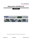
Fig 1.1. Compact, easy-to-install, right-size capacity — the NetGuardian 216 makes it cost-effective to monitor
every site in your network.
Effective, easy-to-install, light-capacity alarm monitoring
The NetGuardian 216 is a compact, LAN-based light-capacity remote telemetry unit. The NG216 is designed for
easy installation at small remote sites, making it cost-effective to deploy alarm monitoring throughout your entire
telecom network.
Right-size capacity for small sites
The NG216 is scaled to the needs of small sites like remote huts, collocation racks and enclosed cabinets —
anyplace where a large-capacity RTU would be more than you need.
·
16 discrete alarm inputs
·
2 analog alarm inputs
·
2 control relays
Reach-through serial port gives LAN access to on-site equipment
The NG216 also features a reach-through serial port. This port provides remote users with LAN-based Telnet
access to a variety of on-site telecom equipment, including switches, radios, PBXs and many other devices.
SNMP or T/Mon NOC
The NetGuardian 216 can report alarms to any SNMP manager or to the DPS Telecom T/Mon NOC Remote
Alarm Monitoring System. The NG216 can report SNMP over UDP or TCP and can report to T/Mon NOC over
UDP, TCP, serial port or T202 modem connection.
Easy installation and configuration
Since it's LAN-based, the NetGuardian 216 installs quickly and easily, without the expense of laying dedicated
lines.
The unit mounts in any 19" or 23" rack and occupies only 1 RU. The unit has simple rear-panel connectors for
alarm inputs.
The NG216 ships with T/NG216, a free Windows-based configuration utility. You can configure and provision
the unit on-site through the craft port or remotely over LAN — so you don't have to physically drive to the site
just to change a setting.
The NetGuardian 216 stores its configuration information in nonvolatile RAM, where it is retained even if the
unit loses power.
2
2 Shipping List
Please make sure all of the following items are included with your NetGuardian 216. If parts are missing, or if
you ever need to order new parts, please refer to the part numbers listed and call DPS Telecom at
1-800-622-3314.
NetGuardian 216
D-PK-NG216
NetGuardian 216 User Manual
(PDF Manual, MIBs and T/NG216 Software)
6 ft. DB9M-DB9F Download Cable
D-PR-045-10A-04
19" Rack Ear
x4
Four 3/8" Ear Screws
NetGuardian 216 Resource CD
14 ft. Ethernet Cable
D-PR-923-10A-14
Wall Mount Bracket
x2
Two Standard Rack Screws
3
x2
Two Metric Rack Screws
Power Connector Plug
Pads
Two 1/2-Amp GMT Fuse
4-Pin Connector Plug
4
3 Specifications
Discrete Alarm Inputs:
16 (reversible)
Analog Alarm Inputs:
2
Analog Input Range:
–90 to 90 VDC or 4 to 20 mA
Analog Thresholds:
4
Control Relays:
2
Protocols:
SNMP
DCPx, DCPf, DCP, DCP1 (T/Mon NOC reporting)
Dimensions:
1.720" H x 8.375" W x 6.626" D (4.369 cm x 21.273 cm x 16.830 cm)
1.720" H x 10.489" W x 6.636" D (4.369 cm x 26.641 cm x 16.855 cm)
Weight: 1.8425 lb (Wide-Case model)
Normal NG216 Case
NG216 Wide Case
Mounting:
19" or 23" rack
Power Input:
–48 VDC (–48 to –70 VDC)
Optional -48 VDC from 110 VAC wall transformer
Current Draw:
200 mA
Fuse:
1/2 Amp GMT
Interfaces:
1 RJ45 10BaseT Ethernet port
1 50-pin connector (alarm inputs and control outputs)
1 4-pin connector (analog alarm inputs)
1 DB9 front-panel craft port
1 DB9 serial port
Visual Interface:
8 LEDs
Audible Notification:
Alarm speaker with volume control and silence button
Operating Temperature:
32°–140° F (0°–60° C)
Operating Humidity:
0%–95% noncondensing
5
4 Installation
4.1 Tools Needed
To install the NetGuardian, you'll need the following tools:
Phillips No. 2 Screwdriver
Small Standard No. 2 Screwdriver
PC with T/NG216 installed
4.2 Mounting
Fig. 4.2.1. The NetGuardian 216 can be flush or rear-mounted
The compact NetGuardian 216 occupies only half the width of a standard rack unit. Only one rack ear is supplied
with the NetGuardian 216, and the rack ear can be mounted on the left or right side of the unit. The NetGuardian
216 mounts in a 19" or 23" rack, and can be mounted on the right or left, in the flush-mount or rear mount
locations, as shown in Figure 4.2.1.
The rack ears can be rotated 90° for wall mounting or 180º for other mounting options not shown.
Use the included wall mount bracket to mount the NetGuardian 216 vertically on the wall.
6
4.3 Power Connection
Fig. 4.3.1. Power connector.
The NetGuardian 216's power connector is a screw terminal barrier plug, located on the left side of the back
panel. (See Figure 4.3.1)
Before you connect a power supply to the NetGuardian 216, test the voltage of your power supply:
·
Connect the black common lead of a voltmeter to the ground terminal of the battery, and connect the red
lead of the voltmeter to the battery's –48 VDC terminal. The voltmeter should read between –43 and –53
VDC. If the reading is outside this range, test the power supply.
To connect the NetGuardian to a power supply, follow these steps:
1. Remove the fuse from the front panel of the NetGuardian 216. Do not reinsert the fuse until all power
and network connections have been made.
2. Remove the power connector plug from the NetGuardian 216's power connector. Note that the plug can
be inserted into the power connector only one way — this ensures that the barrier plug can only be
reinserted with the correct polarity. Note that the –48V terminal is on the left and the GND terminal is
on the right.
3. Insert a battery ground into the power connector plug's right terminal and tighten the screw; then
insert a –48 VDC line to the plug's left terminal and tighten its screw.
4. Push the power connector plug firmly back into the power connector.
5. Reinsert the fuse to power up the NetGuardian 216. The PWR LED by the power connector will light
GREEN. The front panel LEDs will flash RED and GREEN.
4.4 LAN Connection
7
Fig. 4.4.1. Ethernet port
To connect the NetGuardian 216 to the LAN, insert a standard RJ45 Ethernet cable into the 10BaseT Ethernet
port on the back of the unit. (See Figure 4.4.1.) If the LAN connection is OK, the LNK LED will light SOLID
GREEN.
RJ45 Ethernet Connection
8
7
6
5
4
3
2
1
Receive In– (RI–)
Receive In + (RI+)
Transmit Out– (TO–)
Transmit Out + (TO+)
Fig. 4.4.2 Ethernet connection pinout
The pinout for the RJ45 connection is shown in Figure 4.4.2, above.
8
4.5 Discrete Alarms
Dry Contact
Contact to Ground
NetGuardian 216 case
NetGuardian 216 case
GND
GND
Alarm
Alarm
– Batt.
– Batt.
Note: Make sure that grounds have a common reference —
this is usually done by tying grounds together.
Fig. 4.5.1. Discrete alarm points can connect as a dry contact or a contact to ground
The NetGuardian 216 features 16 discrete alarm inputs — also called digital inputs or contact closures. Discrete
alarms are either activated or inactive, so they're typically used to monitor on/off conditions like power outages,
equipment failures, door alarms and so on.
The NetGuardian 216's discrete alarm points are single-lead signals referenced to ground. The ground side of
each alarm point is internally wired to ground, so alarm points can connect either as a dry contact or a contact to
ground.
In a dry contact alarm, the alarm lead brings a contact to the ground lead, activating the alarm.
In a contact to ground alarm, a single wire brings a contact to an external ground, activating the alarm.
For a diagram, see Figure 4.5.1, above.
You can reverse the polarity of each individual discrete alarm point, so that the alarm is activated when the
contact is open. To reverse the polarity of an alarm point, use the included T/NG216 configuration software. For
instructions, see Section 6.6, "Alarms Tab: Alarm Description, Polarity and Trap Options."
9
4.6 50-Pin Alarm and Control Relay Connector
Fig. 4.6.1. Main 50-pin alarm and control relay connector
The primary connector for discrete alarms, analog alarms and control relays is the 50-pin connector on the
NetGuardian 216's back panel. (See Figure 4.6.1, above.)
Note: You can optionally connect analog inputs through the 4-pin barrier plug connector, instead of the 50-pin
connector. For more information, see Section 4.8.1, "Optional 4-Pin Analog Alarm Connector."
4.6.1 50-Pin Connector Pinout Table
Discretes 1–16
Control Relays 1–2*
GND
ALM
ALM 1
1
26
ALM 2
2
27
ALM 3
3
28
ALM 4
4
29
ALM 5
5
30
ALM 6
6
31
ALM 7
7
32
ALM 8
8
33
ALM 9
9
34
ALM 10
10
35
ALM 11
11
36
ALM 12
12
37
ALM 13
13
38
ALM 14
14
39
ALM 15
15
40
ALM 16
16
41
Analogs 1–2
NO
NC
CO
CTRL 1
17
42
43
CTRL 2
19
44
18
+
–
ANA 1
23
48
ANA 2
24
49
Fuse Alarm**
FA
GND
NO
CO
20
45
GND
25
* NO = Normally Open, NC = Normally Closed,
CO = Common
** Control relay is closed if fuse blows.
Table 4.6.1.A. 50-pin connector pinout
50
10
4.6.2 50-Pin Connector Pinout Diagram
GND
1
GND
2
GND
3
GND
4
5
GND
GND
6
7
GND
8
GND
9
GND
10
GND
GND
11
GND
12
13
GND
GND
14
GND
15
GND
16
CTRL 1 NO 17
CTRL 2 CO 18
CTRL 2 NO 19
FA NO
20
21
Unused
Unused
22
ANA 1 +
23
24
ANA 2 +
25
GND
ALM 1
26
27
ALM 2
28
ALM 3
29
ALM 4
30
ALM 5
31
ALM 6
32
ALM 7
33
ALM 8
34
ALM 9
35
ALM 10
ALM 11
36
ALM 12
37
ALM 13
38
ALM 14
39
40
ALM 15
41
ALM 16
42 CTRL 1 NC
43 CTRL 1 CO
44 CTRL 2 NC
45
FA CO
46
Unused
Unused
47
ANA 1 –
48
49
ANA 2 –
50
GND
ALM = Alarm
ANA = Analog
CTRL = Control Relay
GND = Ground
FA = Fuse Alarm
NO = Normally Open
NC = Normally Closed
CO = Common
Fig. 4.6.2.1. 50-pin connector pinout
11
4.7 Optional Wire-Wrap Back Panel
Fig. 4.7.1 The wire-wrap back panel
The optional wire-wrap back panel provides wire-wrap connections for the NetGuardian's alarms (discrete and
analog) and control relays. Screw the board into the holes on either side of the "Discretes 1-16/Analogs
1-4/Relays 1-2 connector" (as shown in Figure 4.7.1). To connect discrete alarms, analog alarms, and control
relays to the wire-wrap panel, connect them to the pin block on the front of the panel.
Caution: Analog Channels 3 and 4 on the Wire-Wrap Panel correspond to Analog Channels 1 and 2 on the
NetGuardian.
12
4.8 Optional 66 Block Connector
Fig. 4.8.1. Optional 66 block connector pinout
The NetGuardian 216 is also available with an optional 66 Block Connector for connecting discrete alarms,
analog alarms and control relays. Pinout and wire color coding for the 66 Block are shown in Figure 4.8.1.
13
4.9 Analog Alarms
The NetGuardian's two analog alarm inputs measure continuous ranges of voltage or current. Analog alarms are
typically used to monitor battery voltage, charging current, temperature or other continuously variable
conditions.
The measurement range of the analog channels is –90 to +90 VDC or 4 to 20 mA.
You can connect analog alarm inputs to the NetGuardian 216 by using either the main 50-pin connector or the
optional 4-pin analog alarm connector. For the 4-pin analog connector's pinout information, see Section 4.8.1,
"Optional 4-Pin Analog Connector."
By default, the analog inputs are configured to measure voltage. You can switch the analog inputs to measure
current by resetting jumpers on the NetGuardian 216's circuit board. For instructions, see Section 4.8.2,
"Switching Analog Alarms to Current Operation."
4.9.1 Optional 4-Pin Analog Connector
Fig. 4.8.1.1. 4-pin analog alarm input connector
The 4-pin analog alarm input connector provides an optional connection for analog alarms only.
You can connect analog inputs to EITHER the primary 50-pin alarm connector OR the 4-pin connector, but not
both at the same time.
The 4-pin connector is a screw terminal barrier plug similar to the power connector. To connect analog inputs,
remove the connector plug, connect the leads to the appropriate terminals and reinsert the barrier plug. Note that
the plug can be inserted into its socket only one way — this ensures that the connector plug can only be
reinserted with the alarm inputs aligned correctly.
Analogs
1A
2A
1B
2B
ANA 1 +
ANA 2 –
ANA 1 –
ANA 2 +
Fig. 4.8.1.2. 4-pin analog connector pinout
The pinout for the 4 pin analog connector is shown in Figure 4.8.1.2, above.
14
4.9.2 Switching Analog Alarms to Current Operation
Fig. 4.8.2.1. Adjustable jumpers on the NetGuardian 216 circuit board
By default, the analog inputs are configured to measure voltage. You can switch the analog inputs to measure
current by resetting jumpers on the NetGuardian 216's circuit board.
To rest the analog alarm voltage/current jumpers, follow these steps:
1. Make sure the NetGuardian 216 is depowered and disconnected from all network connections.
2. Remove the screws from the sides of the NetGuardian 216 case.
3. Slide the top cover of the case off to expose the circuit board.
4. The adjustable jumpers are shown in Figure 4.8.2.1. Both alarm inputs can be individually configured for
current or voltage operation.
CAUTION:
The Jumper labeled Analog 3 controls the voltage/current settings for Analog Input 1, and the Jumper
labeled Analog 4 controls Analog Input 2.
Jumper installed for current
Current
+
250 Ohm
Shunt
-
4 to 20 mA
Current Source
Transducer
Analog
Channel
Input
Jumper removed for voltage
Voltage
+
Voltage Source
Transducer
Analog
Channel
Input
Unjumpered/Open Position:
Voltage Operation (default)
Jumpered/Closed Position:
Current Operation
-
Fig. 4.8.2.2. Jumper settings for analog alarms inputs
15
5. By default, both jumpers are in the unjumpered/open position, which corresponds to voltage operation,
as shown in Figure 4.8.2.2. To reset an analog alarm input to current operation, reset its jumper in the
closed position.
Note: Each jumper inserts a 250-ohm shunt resistor across the input. This must be taken into account
when defining the analog input reference scale. For more information, see Section 6.9.1, "Analog
Channel Scaling Reference Tool."
6. Slide the top cover of the case back into position and replace the screws.
7. Reconnect and power up the NetGuardian 216.
4.10 Back Panel Serial Port
Fig. 4.9.1. Serial port
The NetGuardian 216's DB9 RS-232 reach-through serial port is located on the back panel, where it is labeled
"Primary," as shown in Figure 4.9.1. The serial port can be used for three different functions:
·
Reach-through proxy connection for LAN-based Telnet access to switches, radios, PBXs and other
equipment
·
Alarm reporting to the T/Mon NOC Remote Alarm Monitoring System over an RS-232 serial line
·
Alarm reporting to T/Mon NOC over a T202 modem connection
Note: If the serial port is configured for alarm reporting to T/Mon NOC, the port is not available for use as a
reach-through proxy port.
For instructions on configuring the serial port, see Section 6.5.1, "DCP Channel: T/Mon NOC Alarm Reporting
Options," and Section 6.5.2, "Reach-through Channel."
16
When used as a reach-through proxy port, the serial port has the pinout shown in Figure 4.9.2, below.
RX
TX
GND
5 4 3 2 1
9 8 7 6
RTS
CTS
DB9F RS-232
Pin #
Signal
Description
1
2
3
4
5
6
7
8
9
NC
TX
RX
DSR
GND
NC
CTS
RTS
NC
Not connected
Transmit data
Receive data
Data set ready
Ground
Not connected
Clear to send
Request to send
Not connected
Fig. 4.9.2. Reach-through proxy port pinout
When used as a T202 modem port (optional), the serial port has the pinout shown in Figure 4.9.3, below.
RX+
TX+
5 4 3 2 1
9 8 7 6
TX–
RX–
DB9F T202 Port
Pin #
Signal
Description
1
2
3
4
5
6
7
8
9
TX+
NC
NC
RX+
NC
TX–
NC
NC
RX–
Transmit positive
Not connected
Not connected
Receive positive
Not conntected
Transmit negative
Not connected
Not connected
Receive negative
Fig. 4.9.3. T202 modem port pinout
When using a RS-232 Bridging Docking Pad (optional), the serial port has the pinout shown in Figure 4.9.4,
below.
BRX
HRX
GND
5 4 3 2 1
9 8 7 6
HTX
BTX
DB9F RS-232 Port
Pin #
Signal
Description
1
2
3
4
5
6
7
8
9
HRX
NC
NC
BRX
GND
BTX
NC
NC
HTX
Host receive data
Not connected
Not connected
Bridge receive data
Ground
Bridge transmit data
Not connected
Not connected
Host transmit data
Fig. 4.9.4. RS-232 Bridging port pinout
17
4.11 Craft Port
Fig. 4.10.1. Craft port
Use the front panel craft port to connect the NetGuardian 216 to a PC for onsite unit configuration. To use the
craft port, connect the included DB9 download cable from your PC's COM port to the craft port. For instructions
on using the included T/NG216 configuration software, see Section 5, "T/NG216 Configuration Software."
RX
TX
GND
5 4 3 2 1
9 8 7 6
RTS
CTS
DB9F RS-232
Pin #
Signal
Description
1
2
3
4
5
6
7
8
9
NC
TX
RX
DSR
GND
NC
CTS
RTS
NC
Not connected
Transmit data
Receive data
Data set ready
Ground
Not connected
Clear to send
Request to send
Not connected
Fig. 4.10.2. Craft port pinout
The craft port pinout is shown in Figure 4.10.2, above.
18
5 T/NG216 Configuration Software
T/NG216, the Windows-based software utility included with your NetGuardian 216, provides a full suite of tools
for unit configuration, turnup and testing.
With T/NG216, you can:
·
Configure and provision the NetGuardian 216
·
Read and write configuration files to NetGuardian 216 units in the field over LAN or local craft port
connection
·
Create and save configuration files to your local PC — this is great if you want to create a standard
configuration for all your NG216 units, or if you want to create batches of configuration files for remote
LAN upload
·
Monitor alarm points and operate control relays for turnup and testing
·
Monitor live, real-time voltage or current values from the NetGuardian 216's analog alarm inputs
·
Analyze network traffic between the NetGuardian 216 and its alarm master
·
Load firmware updates
To install T/NG216 on your PC, run the installer program included on the NetGuardian 216 Resource CD.
5.1 T/NG216 PC Requirements
To run T/NG216, DPS Telecom recommends a Windows-based PC with the following specifications:
Operating System:
Windows 9x, NT, ME, 2000 or XP
Processor:
333 MHz or better
Color Setting:
16 bit
Screen Resolution:
1024 x 768
Note: T/NG216 may not work properly on slower machines if the display is set for 256 colors.
19
5.2 Starting T/NG216 — You MUST Read This Section
Fig. 5.2.1. Select a mode … but first check your communication settings
To start T/NG216, choose its program shortcut from the Windows Start menu. When T/NG216 starts, it will first
display the mode selection dialog shown in Figure 5.2.1.
Your choices are:
Turn-up and Test:
Monitor alarms, control relays and set date and time
Editor:
Configure options and provision NetGuardian 216 unit
Analyze:
View NetGuardian 216 communication in hexadecimal or ASCII format
Load Firmware:
Install firmware updates on the NetGuardian 216
Close:
Start T/NG216 without choosing a mode
!
Important!
If you need to change T/NG216's communication settings, click CLOSE. If you select a mode, T/NG216's
communication settings are LOCKED.
By default, a new T/NG216 installation is configured to connect to the NetGuardian 216 over a physical cable
connection between your PC's Communications Port 1 (COM1) and the NG216's front panel craft port. You
CANNOT change this setting while in Turn-up and Test, Editor, Analyze or Load Firmware Mode.
If you are connected to the NetGuardian 216 through a COM1–to–Craft Port connection, go ahead and
select the mode you want to use. But keep in mind that T/NG216 saves communication settings between
20
sessions — if you ever change your communication settings, you should double-check your settings the next time
you start the program.
If you want to make a LAN connection to a remote NetGuardian 216, or if you want to connect to the craft
port using a different PC COM port, click Close in the mode selection dialog. Change your communication
settings, and then select the mode you want. (For more information, see Section 5.4, "Connecting to the
NetGuardian 216 via Craft Port" and Section 5.5, "Connecting to the NetGuardian 216 via LAN.")
5.3 Changing Modes in T/NG216
Reboot
Editor
NG
216
Turn-up
Analyze
and Test
Load
Advanced
Firmware
Fig. 5.3.1. Change mode buttons on the T/NG216 toolbar
While running T/NG216 you can change modes by clicking one of the change mode buttons in the T/NG216
toolbar. (See Figure 5.3.1.) The toolbar also features a button for rebooting the connected NetGuardian 216. In
most cases, you won't need to reboot the NetGuardian 216 — if the unit needs to be rebooted to put an
configuration change into effect, T/NG216 will automatically reboot the unit.
If you point to a toolbar button with the mouse cursor, the button's name will appear in a tooltip by the cursor and
in the status bar at the bottom of the T/NG216 window.
Fig. 5.3.2. Exit mode button
To exit a mode, click the Exit button on the far right of the toolbar. (See Figure 5.3.2, above.)
!
Important!
ALWAYS click Exit BEFORE changing communication settings. You CANNOT change communication
settings while in Turn-up and Test, Editor, Analyze or Load Firmware Mode.
21
It's especially important to verify your communication settings when you are connecting to remote NetGuardian
216 units over LAN. After you enter Editor Mode and start entering configuration data, you cannot change the IP
address — you are locked onto the last NetGuardian 216 you connected to, and if you click the Write to unit
button, the new configuration will be written to the last IP address entered, overwriting your last
configuration work.
Fig. 5.3.3. Action menu
You can also change modes by selecting a mode from the Action menu. (See Figure 5.3.3., above.) The Action
menu also has a command for opening the Protocol Window. This is an internal DPS Telecom command that
you won't need to use unless advised to by DPS Telecom Tech Support personnel.
!
Important!
The Action menu Exit command and the toolbar Exit button are two separate commands. The Action menu Exit
command quits the T/NG216 program. The toolbar Exit button just exits the currently active mode. If you just
want to change your communication settings, click the Exit button.
5.4 Connecting to the NetGuardian 216 via Craft Port
Fig. 5.4.1. Craft port
The simplest way to connect to the NetGuardian 216 is over a physical cable connection between your PC's
Communications Port 1 (COM1) and the NG216's front panel craft port.
Use the included DB9 download cable to connect your PC's COM port to the NetGuardian 216 craft port. (For
the pinout of the craft port, see Section 4.10, "Craft Port.")
22
To connect over the craft port, just start T/NG216 and choose the mode you want to use. (See Section 5.2,
"Starting T/NG216.")
Fig. 5.4.2. Communications error message
If T/NG216 can't connect to the NetGuardian 216, the program will display the error message shown in Figure
5.4.2, above. Make sure that the NetGuardian 216 unit is powered and double-check the cable connection.
Fig. 5.4.3. Use the COM Port command on the Settings menu to switch to a different COM port
If you want to connect to the NetGuardian 216 over a LAN connection or a different COM port, click the COM
Port command on the Settings menu. (See Figure 5.4.3.) This opens the Communication Mode dialog box.
(See Figure 5.4.4.)
Fig. 5.4.3. Enter a different COM port number here
Click Craft Port and enter a new number in the COM Port Number box.
Note: T/NG216 saves communication settings between sessions, so when you next start T/NG216, the program
will be configured to use the last communication settings used.
!
Important!
You CANNOT change T/NG216's communication settings while in Turn-up and Test, Editor, Analyze or
23
Load Firmware Mode. Before changing communication settings, click EXIT on the T/NG216 Toolbar.
When T/NG216 is in Turn-up and Test, Editor, Analyze or Load Firmware Mode, the program's communication
settings are LOCKED and cannot be changed. While T/NG216 is any of these modes, the program will read
from and write to the NetGuardian 216 unit that is connected over the last communications channel used.
If you always use a craft port connection, this isn't a problem, since you'll make a new physical cable connection
every time you connect to a different NG216 unit. Just keep T/NG216 configured to use your preferred COM
port (probably the default setting, COM1). Keep in mind that T/NG216 saves communication settings between
sessions, so if you change your communication settings, double-check your settings the next time you start the
program.
For important information about LAN connections, see Section 5.5, "Connecting to the NetGuardian 216
via LAN."
To close a mode and change communication settings, always click EXIT button on the TOOLBAR. If you
choose the Exit command from the Action menu, you will quit the T/NG216 program. For more information,
see Section 5.3, "Changing Modes in T/NG216."
5.5 Connecting to the NetGuardian 216 via LAN
You can also use T/NG216 to remotely connect to NetGuardian 216 units in the field over LAN. This is a very
convenient way to provision a series of NetGuardian units, especially if you're working from a standardized
configuration file.
[WARNING: When working with NetGuardian 216s over LAN, be very careful that you're connected to
the correct unit BEFORE writing a configuration to unit memory. See important warnings at the end of
this section.]
Before you can make a remote LAN connection to the NetGuardian 216, you need to assign the NetGuardian 216
an IP address on your network. (If you're not sure what IP address to assign, check with your network
administrator.)
In order to assign the NetGuardian 216 an IP address, you have to establish a temporary connection to the unit.
There are two ways to make a temporary connection to the NetGuardian 216:
The Easy Way: If you have physical access to the NetGuardian 216, the easiest thing to do is connect to the unit
through the craft port and then assign it an IP address. After you've done that, you can complete the rest of the
unit configuration over a remote LAN connection, if you want. For instructions, see Section 5.5.1, "Assigning an
IP Address via Craft Port."
The Slightly More Complicated Way: If you DON'T have physical access to the NetGuardian, you can connect
to the NetGuardian 216 over a temporary LAN connection. You can create a temporary connection by
temporarily changing the IP address and subnet mask of your PC to match the factory-default settings of the
NetGuardian 216. For instructions, see Section 5.5.2, "Assigning an IP Address via Temporary LAN
Connection."
24
Once you have assigned an IP address to the NetGuardian 216, follow these steps to make a remote LAN
connection to the unit:
Fig. 5.5.1. Use the COM Port command on the Settings menu to select a LAN connection
1. Start T/NG216. Click Close in the mode selection dialog box. (See Section 5.2, "Starting T/NG216.")
2. Choose COM Port from the Settings menu to open the Communication Mode dialog box. (See Figure
5.5.1, above.)
Fig. 5.5.2. Enter the NetGuardian 216's IP address here
3. In the Communications Mode dialog box, click TCP/IP. Type the NetGuardian 216's IP address in the
IP Address box. The NetGuardian 216 always connects over LAN using Port 2002, so the Port box
cannot be changed.
Fig. 5.5.3. Communications error message
4. To verify the connection, switch to Turn-up and Test Mode, or switch to Editor Mode and click the Read
from Unit button. (For information about switching modes, see Section 5.3.) If T/NG216 can't connect
to the NetGuardian 216, the program will display the error message shown in Figure 5.4.2.4, above. If
possible, make sure that the NetGuardian unit is powered and connected to the network. Check to make
sure there are no firewalls or port-blocking routers between your PC and the NetGuardian 216.
Note: T/NG216 saves communication settings between sessions, so when you next start T/NG216, the program
will be configured with the last communications settings used.
!
Important!
You CANNOT change T/NG216's communication settings while in Turn-up and Test, Editor, Analyze or
25
Load Firmware Mode. Before changing communication settings, click EXIT on the T/NG216 Toolbar.
When T/NG216 is in Turn-up and Test, Editor, Analyze or Load Firmware Mode, the program's communication
settings are LOCKED and cannot be changed. While T/NG216 is any of these modes, the program will read
from and write to the NetGuardian 216 unit that was connected over the last communications channel used.
When connecting to NetGuardian 216 units through a LAN connection, you MUST select the unit's IP
address BEFORE you make any configuration changes. ALWAYS check the IP address BEFORE
connecting to a NG216 unit via LAN. Once you enter Editor Mode and start entering configuration data, you
CANNOT change the IP address — if you click the Write to unit button, the new configuration will be
written to the last IP address entered, overwriting your last configuration work.
To close a mode and change communication settings, always click EXIT on the TOOLBAR. If you choose
the Exit command from the Action menu, T/NG216 will quit. For more information, see Section 5.3, "Changing
Modes in T/NG216."
5.5.1 Assigning an IP Address via Craft Port
Follow these steps to configure the NetGuardian over a craft port connection:
1. Connect your PC to the NetGuardian 216's craft port and start T/NG216. (For instructions, see Section
5.4, "Connecting to the NetGuardian 216 via Craft Port.")
2. Click Editor in the mode selection dialog box. (See Section 5.2, "Starting T/NG216.")
Fig. 5.5.1.1. Read from Unit Button
3. Click the Read from Unit button on the Editor Mode toolbar to download the current unit
configuration from the NetGuardian 216 unit. This is an important double check to make sure you know
what unit you're working with and what settings you're changing.
4. T/NG216 will prompt you to enter a password. If you haven't assigned the NetGuardian a password, use
the default password, dpstelecom. (Passwords are case-sensitive; the default password is all
lower-case.)
5. There will be a brief pause as T/NG216 downloads the configuration file.
26
Fig. 5.5.1.2. Enter the NetGuardian 216's IP address here
6. Click the Device tab. In the Ethernet Port area, enter the NetGuardian 216 unit's assigned IP address,
subnet mask and gateway. (See Figure 5.5.1.2, above.)
7. You need to enter a confirmation password to write the new configuration to NVRAM. Type the
password in the Confirm box in the NG216 Options area. (See Figure 5.4.1.2.) For new units you can
use the default password: dpstelecom.
Fig. 5.5.1.3. Write to Unit Button
8. Click the Write to Unit button (see Figure 5.5.1.3., above) to write the new configuration to the
NetGuardian 216's NVRAM.
You can now connect to the NetGuardian 216 over LAN, using the IP address you assigned. For instructions on
connecting over LAN, see Section 5.5, "Connecting to the NetGuardian 216 via LAN."
5.5.2 Assigning an IP Address via Temporary LAN Connection
Follow these steps to configure the NetGuardian over a temporary LAN connection:
1. Look up your PC's current IP address and subnet mask, and write this information down.
2. Reset your PC's IP address to 192.168.1.200.
3. Reset your PC's subnet mask to 255.255.0.0. You may have to reboot your PC to apply your changes.
4. Start T/NG216.
5. Click Close in the mode selection dialog box. (See Section 5.2, "Starting T/NG216.")
27
Fig. 5.5.2.1. Use the COM Port command on the Settings menu to connect to the NetGuardian 216's default IP
address
6. Chose COM Port from the Settings menu to open the Communications Mode dialog box.
Fig. 5.4.2.2. Enter the NG216's default IP address — 192.168.1.100 — here
7. In the Communications Mode dialog box, click TCP/IP. Type 192.168.1.100 (this is the NetGuardian's
factory-default IP address) in the IP Address box and click Set. The NetGuardian 216 always connects
over LAN using Port 2002, so the Port box cannot be changed.
8. Switch to Editor Mode. (Choose Editor from the Action menu, press Ctrl+E, or click the Editor button
in the toolbar — for details, see Section 5.3, "Changing Modes in T/NG216.")
Fig. 5.5.2.3. Read from Unit Button
9. Click the Read from Unit button on the Editor Mode toolbar to download the current unit
configuration from the NetGuardian 216 unit. This is an important double check to make sure you know
what unit you're working with and what settings you're changing.
10. T/NG216 will prompt you to enter a password. If you haven't assigned the NetGuardian a password, use
the default password, dpstelecom. (Passwords are case-sensitive; the default password is all
lower-case.)
28
Fig. 5.5.2.4. Communications error message
11. If T/NG216 can't connect to the NetGuardian 216, the program will display the error message shown in
Figure 5.5.2.4, above. If possible, make sure that the NetGuardian unit is powered and connected to the
network.
12. If the connection is successful, there will be a brief pause as T/NG216 downloads the configuration file.
Fig. 5.5.2.5. Enter the NetGuardian 216's permanent IP address here
13. Click the Device tab. In the Ethernet Port area, enter the NetGuardian 216 unit's assigned IP address,
subnet mask and gateway. (See Figure 5.5.2.3, above.)
14. You need to enter a confirmation password to write the new configuration to NVRAM. Type the
password in the Confirm box in the NG216 Options area. (See Figure 5.5.2.3.) For new units you can
use the default password: dpstelecom.
Fig. 5.5.2.6. Write to Unit Button
15. Click the Write to Unit button (see Figure 5.5.2.4., above) to write the new configuration to the
NetGuardian 216's NVRAM.
16. Change your PC's IP address and subnet mask back to their original settings.
You can now connect to the NetGuardian 216 over LAN, using the IP address you assigned. For instructions on
connecting over LAN, see Section 5.5, "Connecting to the NetGuardian 216 via LAN."
29
6 Configuration
6.1 T/NG216 Editor Mode
Open Saved
Configuration
File
Save As
Save
Configuration
File to PC Disk
Delete
Create New
Configuration File
Configuration
from PC Disk
File
Write
Configuration
File to NG216
NVRAM
Read
Configuration
from NG216
NVRAM
Exit Editor
Mode
Fig. 6.1.1. Editor Mode toolbar
T/NG216's Editor Mode provides complete tools for configuring the T/NG216. With Editor Mode, you can
define NG216 configuration settings, read and write configurations to the NG216's NVRAM memory, and save
NG216 configuration files on disk.
Configuration settings are defined in the several tabs in the T/NG216 Editor window. Each tab is described in
detail in the following sections.
The Editor Mode toolbar (Figure 6.1.1, above), provides commands for working with NG216 configuration files.
If you point to a toolbar button with the mouse cursor, the button's name will appear in a tooltip by the cursor and
in the status bar at the bottom of the T/NG216 window.
6.2 Reading and Writing Configuration Files on PC Disk
NetGuardian 216 configurations can be saved to and loaded from a floppy or PC hard disk or network drive.
Working with saved configuration files is a very convenient way to configure multiple NetGuardian 216 units —
you can define a basic configuration for all your units, save it on disk, and use it (with appropriate changes) for
all of your individual units.
Commands for working with configuration files on your PC are located on the left side of the Editor Mode
toolbar (see Figure 6.1.1). The available commands are:
New:
Create a new, blank configuration. (Note: This will clear all T/NG216 configuration settings; you
will be prompted to save the current configuration.)
Open:
Load an existing saved configuration file from disk.
Save:
Save current configuration.
Save As:
Save current configuration as a new file.
Delete:
Delete a saved configuration file.
30
6.3 Reading and Writing Configuration Files to NetGuardian 216
NVRAM
The Editor Mode toolbar also provides tools for reading and writing configurations to the NetGuardian 216's
NVRAM memory. The Write to unit and Read from unit buttons are located in the center of the toolbar (see
Figure 6.1.1).
DOD
It's a good idea to always load the existing configuration from unit NVRAM before defining configuration
options. This is an important double check to make sure you know what unit you're working with and what
settings you're changing.
Changes to the NetGuardian configuration DO NOT take effect until you click the Write to unit button and
reboot the unit. The Write to unit command writes all current T/NG16 configuration settings to the
NetGuardian 216's NVRAM, erasing all previous settings.
After writing the configuration to NG216 NVRAM, T/NG216 will automatically reboot the NG216 unit.
31
6.4 Device Tab: General NG216 Options
Fig. 6.4.1 The Device tab provides general configuration options
The Device tab (Figure 6.4.1) provides options for basic NetGuardian 216 setup:
Device Name:
Assign the NetGuardian 216 a name of your choice. For easy identification, it's a good
idea to assign a name that will be meaningful to everyone who uses the NetGuardian
216.
Device Location:
Type in the physical location of the NetGuardian 216. This is very useful for keeping
track of different units.
Contact Number:
Type in a phone number or email address for the person responsible for the site.
Alarm Qual Time:
This is a great tool for controlling nuisance alarms. If an alarm point fluctuates in and
out, you can set a minimum duration that a point must be activated before the
NetGuardian 216 reports an alarm. Enter alarm qualification time in milliseconds. The
available range is 100–9000 milliseconds, or 0.1–9 seconds. The Alarm Qual Time
setting affects all 16 discrete alarm points.
32
6.4.1 Ethernet Port Options
The Ethernet Port area provides options for configuring the NetGuardian 216's IP address:
Unit Address:
Type in the NetGuardian 216's assigned IP address on your network. (For step-by-step
instructions, see Section 5.4.1, "Assigning an IP Address via Craft Port," and Section
5.4.2, "Assigning an IP Address via LAN.")
Subnet Mask:
Type in the NG216's assigned subnet mask. A subnet mask controls whether IP data
packets transmitted between the NetGuardian 216 and its alarm master stay within the
local network or are forwarded somewhere else on a wide area network. If you're not
sure whether you should assign a subnet mask, check with your network administrator.
Default Gateway:
You only need to enter a default gateway if the NetGuardian 216 is connected to a wide
area network. If you're not sure whether to assign a default gateway, check with your
network administrator. If you're not connected to a WAN, keep the default value,
255.255.255.255.
6.4.2 NG216 Options: Password and Alarm Speaker
The NG216 Options area provides options for configuring the NetGuardian 216's security password and audible
notification:
Password:
This box displays the NetGuardian 216's current security password in asterisks. You
need to enter a password when you connect to the NetGuardian 216 to read or write
configurations, monitor in Turn-up and Test Mode, or monitor communications in
Analyze Mode. The Password box is automatically filled with the current password
when the NG216's configuration is loaded into T/NG216 from NVRAM. Passwords are
case sensitive and must be at least four-characters long. The default password is
dpstelecom — note that that is all lower-case — but you'll obviously want to change
the default to a password you choose.
Confirm:
As a security check, you need to enter the password in this box before you can write a
configuration to the NetGuardian 216's NVRAM. If you don't type in the password,
T/NG216 will prompt you to enter it before continuing. Click the Device tab and enter
the password in the Confirm box.
To change the password, type the new password in the Password box and re-type it in
the Confirm box. Then click the Write to unit button. T/NG216 will prompt you to
type the old password before continuing.
Speaker Enabled:
Checking this box enables the NetGuardian 216's alarm speaker, which will beep to
announce new alarms. Note: The alarm speaker is automatically disabled if the DCP
Channel (T/Mon NOC reporting channel) is turned off.
33
6.5 Channel Tab: Alarm Reporting Options
The Channel tab provides options for configuring alarm reporting to SNMP managers and T/Mon NOC and
options for configuring a reach-through proxy channel:
6.5.1 DCP Channel: T/Mon NOC Alarm Reporting Options
The DCP Channel options configure how the NetGuardian 216 reports alarms to the DPS Telecom T/Mon NOC
Remote Alarm Monitoring System. Your T/Mon NOC alarm reporting options are slightly different, depending
on whether you select alarm reporting over LAN or over a serial connection.
6.5.1.1 Reporting to T/Mon NOC via LAN
Fig. 6.5.1.1.1 DCP Channel options (when alarm reporting over LAN is selected)
Reporting over LAN is very simple to set up; most users can accept the defaults without changing a thing. DCP
over LAN options are shown in Figure 6.5.1.1.1, above. Your choices are:
Protocol:
Choose from OFF, DCPx, DCPf, DCP or DCP1. In most cases, the best choice is to keep the
default setting, which is DCPx. Choosing OFF from this menu turns off alarm reporting to
T/Mon NOC.
Note: Turning off T/Mon NOC alarm monitoring also disables the alarm speaker.
Port Type:
Choose from SERIAL, T202, UDP/IP or TCP/IP. Choosing SERIAL or T202 from this menu
gives you slightly different options; see Section 6.5.1.2 "Reporting to T/Mon NOC via Serial or
T202 Connection."
Note: The Serial and T202 options are functionally the same, with the exception that the T202
option logically inverts the RTS signal, which may be necessary in other types of serial
communications besides T202.
Address:
This box assigns the NetGuardian 216 an ID in T/Mon NOC's Port–Address–Display–Alarm
Point addressing system. Each NetGuardian 216 unit must have a unique address that matches
the address databased for it on T/Mon NOC.
Net Port:
This box displays the UDP/IP or TCP/IP port the NetGuardian 216 uses to communicate with
T/Mon NOC. You don't need to change this setting unless your network administrator wants you
to use a different port or if DPS Telecom Tech Support personnel advise you to change the
setting.
34
6.5.1.2 Reporting to T/Mon NOC via Serial or T202 Modem Connection
Fig. 6.5.1.2.1
DCP Channel options (when alarm reporting over T202 modem connection is selected)
DCP over serial and T202 modem connection options are shown in Figure 6.5.1.2.1, above. Your choices are:
Protocol:
Choose from OFF, DCPx, DCPf, DCP or DCP1. In most cases, the best choice is to keep the
default setting, which is DCPx. Choosing OFF from this menu turns off alarm reporting to
T/Mon NOC.
Note: Turning off T/Mon NOC alarm monitoring also disables the alarm speaker.
Port Type:
Choose from SERIAL, T202, UDP/IP or TCP/IP. Choosing UDP/IP or TCP/IP from this
menu gives you slightly different options; see Section 6.5.1.1 "Reporting to T/Mon NOC via
LAN."
Note: The Serial and T202 options are functionally the same, with the exception that the T202
option logically inverts the RTS signal, which may be necessary in other types of serial
communications besides T202.
Baud Rate:
Choose from 1200, 2400, 4800 or 9600 baud.
For T202 modem connections, the Baud Rate must be either 1200 or 2400 baud.
RTS Lead:
Time carrier is turned on before data is sent, in milliseconds. Available range is 0–255 msec.
RTS Tail:
Time carrier stays on after data is sent, in milliseconds. Available range is 0–255 msec.
For RS-232 connections, both RTS Lead and RTS Tail should be kept at their factory default
setting, which is zero (0).
For T202 modem connections, both RTS Lead and RTS Tail must be set above zero. If you
select T202 in the Port Type menu, RTS Lead will default to 30 msec, and RTS Tail will
default to 10 msec, as shown in Figure 6.5.1.2.1.
35
6.5.2 Reach-through Channel
Fig. 6.5.2.1. Reach-through channel, turned off (left) and on (right)
The Reach-through Channel options configure how the back panel serial port is used.
Note: Reach-through Channel options are not available if the DCP Channel (T/Mon NOC alarm reporting
channel) is set for serial connection.
To turn on the Reach-through Channel, type the TCP/IP port number you want to use in the Reach-through Port
box. (See Figure 6.2.5.1, above.) If you type zero in the box, the Reach-through Channel is turned off.
When the Reach-through Channel is turned on, your options are:
Reach-through Port:
TCP/IP or UDP/IP port remote users will use to communicate with connected
devices.
Reach-through Type:
Choose between UDP/IP and TCP/IP.
Baud Rate:
Choose from 1200, 2400, 4800 or 9600 baud.
RTS Lead:
Time carrier is turned on before data is sent, in milliseconds. Available range is 0–
255 milliseconds.
RTS Tail:
Time carrier stays on after data is sent, in milliseconds. Available range is 0–255
milliseconds.
Note: For RS-232 connections, both RTS Lead and RTS Tail should be kept at
their factory default setting, which is zero (0).
36
6.5.3 Alarm Channel: SNMP Alarm Reporting Options
Fig. 6.5.3.1. Alarm Channel (SNMP alarm reporting) options
The Alarm Channel options configure how the NetGuardian 216 reports alarms to SNMP managers. Your
choices are:
Protocol:
Choose between OFF and SNMP. Choosing OFF from this menu turns off
SNMP alarm reporting.
SNMP Communities:
Get:
Community string for SNMP Get requests.
Set:
Community string for SNMP Set requests.
Trap:
Community string for SNMP Traps.
Note: Make sure that your community strings match those used by the
SNMP manager. Community strings are security passwords; if the strings do
not match, the SNMP manager will not accept Traps from the NetGuardian
216. Community strings are case sensitive.
Primary Trap Destination:
Trap Address:
IP address of the primary SNMP manager.
Trap Port:
UDP/IP port the primary SNMP manager uses to receive Traps. In most
cases, you should keep the default setting, which is 162.
Secondary Trap Destination:
Trap Address:
Trap Port:
IP address of the secondary SNMP manager. If the is no secondary SNMP
manager, keep the default setting, 255.255.255.255.
UDP/IP port the primary SNMP manager uses to receive Traps. In most
cases, you should keep the default setting, which is 162.
37
6.6 Alarms Tab: Alarm Descriptions, Polarity and Trap Options
Fig. 6.6.1. The Alarms tab configures discrete alarm inputs
The Alarms tab (Figure 6.6.1) provides options for configuring the NetGuardian's 16 discrete alarm inputs. Your
choices, for each alarm point, are:
Description:
Type a description of the alarm's function.
Polarity:
Choose between Normal (normally open operation) and Reversed (normally closed operation).
Trap:
Controls whether the NetGuardian 216 sends an SNMP Trap to the SNMP manager when this
alarm is activated. Choose between Yes or No.
Note: Trap option is not available if Alarm Channel (SNMP alarm reporting channel) is turned
off. For more information, see Section 6.5.3, "Alarm Channel: SNMP Alarm Reporting
Options."
6.7 Relays Tab: Control Relay Options
Fig. 6.7.1. The Relays tab configures control relays
The Relays tab (Figure 6.7.1) provides options for configuring the NetGuardian's two control relays. Your
choices, for each control relay, are:
Description:
Type a description of the control's function.
Trap:
Controls whether the NetGuardian 216 sends an SNMP Trap to the SNMP manager when this
control relay is activated. Choose between Yes or No.
Note: Trap option is not available if Alarm Channel (SNMP alarm reporting channel) is turned
off. For more information, see Section 6.5.3, "Alarm Channel: SNMP Alarm Reporting
38
Options."
6.8 System Alarms Tab
Fig. 6.8.1. The System Alarms tab displays internal housekeeping alarms
The System Alarms tab (Figure 6.8.1) displays alarm descriptions for the NetGuardian 216's 7 internal
housekeeping alarms. The only System Alarms option you can set is to choose whether the NetGuardian 216 will
send an SNMP Trap when a system alarm is activated. This option is not available when the Alarm Channel is
turned off.
The NetGuardian 216's System Alarms are:
Default Configuration:
Configuration file loaded on the NetGuardian 216 unit is invalid and the unit has
reverted to the factory-default configuration. The unit must be reprovisioned
with a new configuration.
MAC Address Not Set:
Internal hardware error. Contact DPS Telecom Tech Support at (559) 454-1600
for assistance.
IP Address Not Set:
NetGuardian 216 unit has not been provisioned with an IP address.
SNMP Processing Error:
SNMP OID not recognized or SNMP request invalid. Contact DPS Telecom
Tech Support at (559) 454-1600 for assistance.
SNMP Community Error:
The SNMP community strings provisioned on the NetGuardian 216 do not
match the SNMP manager's community strings. Double-check Alarm Channel
settings on the Channel tab.
LAN Tx Packet Drop:
LAN transmission error. An occasional packet drop is normal, but if the
NetGuardian 216 reports a steady series of packet drops, check to make sure the
NG216 is connected to the LAN. If you're not using the NetGuardian 216 LAN
connection, set IP address to 255.255.255.255.
39
6.9 Analog Alarms Tab
Fig. 6.9.1 The Analog Alarms tab configures the NetGuardian 216's analog alarm inputs
The Analog Alarms tab (Figure 6.9.1) configures the NetGuardian 216's 2 analog alarm inputs. Your choices,
for each analog input, are:
Description:
Type a description of the analog input's function. You must type a description in
this box to enable the analog input. When a description is entered, the display in
the Enabled box will switch from No to Yes. To disable the analog input, delete
the description.
Units:
Type a three-character abbreviation to indicate the display units measured by the
analog input — for example, "F" for degrees Fahrenheit or "RH" for relative
humidity.
Note: The analog inputs natively measure voltage on a range of –90 to +90
VDC. To display other units correctly, the NetGuardian 216 must be provisioned
with a scaling reference to map display unit values to voltage. Entering any
display unit other than "VDC" in the Units box automatically opens the Analog
Channel Scaling Reference tool, where you can enter reference values to scale
the unit display. The current scaling references for the selected analog input are
displayed at the bottom of the Analog Alarms tab (see Figure 6.9.1, above.) For
instructions on using the Analog Channel Scaling Reference tool, see Section
6.9.1, "Analog Channel Scaling Reference Tool."
Note: You can switch the analog inputs to measure current by resetting jumpers
on the NetGuardian 216's circuit board. For instructions, see Section 4.8,
"Switching Analog Alarms to Current Operation."
MjU, MnU, MnO, MjO:
Type in values for Major Under (MjU), Minor Under (MnU), Minor Over
(MnO) and Major Over (MjO) threshold alarms. Threshold values can be
entered in either ascending or descending order for different units. For example,
in Figure 6.9.1, the Battery Level input is set in descending order, from a Major
40
Under of –46 volts (undercharged) to a Major Over of –54 volts (overcharged).
The Temperature input is set in ascending order, from a Major Under of 0° F to
a Major Over of 100° F. Whether threshold values are in ascending or
descending order, they must be continuous range from lowest to highest or
highest to lowest.
Trap:
Controls whether the NetGuardian 216 sends an SNMP Trap to the SNMP
manager when an analog alarm threshold is crossed. Choose between Yes or No.
Note: Trap option is not available if Alarm Channel (SNMP alarm reporting
channel) is turned off. For more information, see Section 6.5.3, "Alarm Channel:
SNMP Alarm Reporting Options."
Enabled:
Displays Yes or No to indicate if the analog input is enabled. To enable the
analog input, type a description in the Description box. To disable the analog
input, delete the description.
6.9.1 Analog Channel Scaling Reference Tool
Fig. 6.9.1.1. Analog Scaling Reference Tool
The NetGuardian 216's analog inputs natively measure voltage on a range of –90 to +90 VDC. To display other
units correctly, the NetGuardian 216 must be provisioned with a scaling reference to map display unit values to
voltage.
The Analog Channel Scaling Reference tool (Figure 6.9.1.1) configures the reference scale for the selected
analog input. To open the Analog Channel Scaling Reference tool, enter a unit abbreviation in the Units box of
the Analog Alarms tab or click the Change button on the Analog Alarms tab.
To define a reference scale, enter a display unit and a corresponding voltage for the minimum and maximum
range of the analog sensor.
For example, the scaling reference shown in Figure 6.9.1.1, above, shows the configuration for an analog alarm
input that is connected to a temperature sensor. The lowest temperature the sensor can measure is –4° F, at which
point the sensor outputs 1.0 VDC. The highest temperature the sensor can measure is 167° F, at which point the
sensor outputs 5.0 VDC. Given these minimum and maximum values, the NetGuardian 216 can calculate the
corresponding display unit for any analog value it detects.
To find out the minimum and maximum range of your analog sensors, check the manufacturers' documentation.
41
Analog Channel Scaling for Current Inputs
You can switch the NetGuardian 216's analog inputs to measure current by resetting jumpers on the NetGuardian
216's circuit board. For instructions, see Section 4.8, "Switching Analog Alarms to Current Operation."
Switching to current operation involves inserting a 250-ohm shunt resistor across the analog alarm input. You
need to take this into account when defining the analog reference scale.
Use Ohm's Law (V=IR) to calculate the voltage drop across the 250-ohm shunt resistor.
For example, let's say you have a sensor whose minimum-maximum output range is 5 mA–15mA.
The sensor's minimum voltage reference would be 1.25 VDC (0.005 amps x 250 ohms).
The sensor's maximum voltage reference would be 3.75 VDC (0.015 amps x 250 ohms).
Enter these voltage values into the Analog Channel Scaling Reference tool to calculate the reference scale.
7 Turn-up and Test Mode
Fig. 7.1. Turn-up and Test Mode, with the Alarm tab selected
Turn-up and Test Mode lets you monitor the NetGuardian 216 from T/NG216. This is a great tool for making
sure the NG216 is configured and operating correctly.
42
7.1 Alarm Tab: Monitor and Log Alarms
The Alarm tab (Figure 7.1) displays and logs alarm events. The Alarm tab consists of two elements, the Alarm
Grid and the Alarm Log.
The Alarm Grid maps standing alarms on a grid of 3 displays. Each display represents 64 points, even though
that is more alarm points than the NG216 has.
Display 1 shows NG216 discrete alarms (Alarm Points 1–16), relays (Alarm Points 17–18) and System Alarms
(Alarm Points 27–32).
Display 2 shows analog threshold alarms for Analog Alarm Input 1 (Alarm Points 1–4).
Display 3 shows analog threshold alarms for Analog Alarm Input 2 (Alarm Points 1–4).
(For a full alarm map, see Section 12.1, "NetGuardian 216 Alarm Map")
When an alarm happens, a red box will appear in the grid cell corresponding to the activated alarm point. The red
box will remain in the cell as long as the alarm is standing.
The Alarm Log maintains a continuously updated list of change of state (COS) alarms. New alarms are added to
the top of the list, so the farther down you scroll, the older the record. Each alarm is listed by its Display and
Alarm Point, its description, whether it's an alarm or a clear, and the date and time.
The Alarm Log only lists alarms while T/NG216 is in Turn-up and Test Mode. Exiting Turn-up and Test Mode,
or quitting T/NG216, clears the Alarm Log.
To clear the Alarm Log while in Turn-up and Test Mode, click the Clear Log button.
Clicking the Copy button copies the Alarm Log to the Windows clipboard. You can then paste the Alarm Log
data to a spreadsheet or text document for analysis or logging.
If the PC Change-of-State Beep box is checked, your PC will beep every time a new alarm happens. To silence
the beep, uncheck the box.
43
7.2 Analog Tab: Display Live Analog Values
Fig. 7.2.1. The Analog tab displays a live reading of the current analog measurements
The Analog tab (Figure 7.2.1) displays a live reading of the values currently measured by the analog alarm
inputs. The display refreshes several times a second, so for practical purposes, it's a continuously updated live
reading.
When you click the Analog tab, a dialog box will ask if you want to download analog channel descriptions. If
you click Yes, the Analog tab will display the alarm description and display units for each analog input.
If the analog input crosses an alarm threshold, a red box will appear in the appropriate cell in the Analog tab
display.
7.3 Relays Tab: Test Control Relay Action
Fig. 7.3.1. The Relays tab tests control relay action
The Relays tab (Figure 7.3.1) provides tools for testing control relay action.
To test a control relay, click the Latch or Mom button.
The Latch button will latch the relay until you click Release.
44
The Mom button will momentarily latch the relay for 600 milliseconds, then release it.
7.4 Date/Time Tab: Set and Synchronize Clock
Fig. 7.4.1. Set and synchronize the NG216's real-time clock
The Date/Time tab (Figure 7.4.1) provides options for setting and synchronizing the NetGuardian 216's real-time
clock.
The real-time clock keeps the correct time even if the unit is shut down or rebooted. This ensures that alarms
always have a correct date/time stamp. The NetGuardian 216 includes a date/time stamp in all SNMP traps.
The top part of the Date/Time tab displays the current time on the NG216 clock.
The bottom part of the Date/Time tab features controls for setting the clock manually. Choose the right time
from the drop-down menus and click Update Date/Time to set the clock.
Clicking the Sync With Local PC button will synchronize the NG216 clock to your PC's clock.
7.5 Tuning Tab: 202 Modem Tuning
The Turn-Up & Test Mode's modem tuning controls allow you to easily measure and adjust dB transmission
levels of the 202 modem to meet industry standards.
With the NetGuardian 216 connected to a power source, you can control frequency levels of the modem using
T\NetGuardian 216 for Windows software. Once you're in Turn-Up & Test Mode:
1. Make sure that you have the VF test set connected to the 202 port to monitor the modem's transmit levels.
2. Begin by pushing the Start button. This will pull the unit's T202 device into tuning mode. When it has
successfully entered tune mode, the button will change to "Stop" and all the other buttons will be enabled. If an
error occurs, make sure that you have a T202 port on your unit and that there is a connection to the unit.
3. Once it has connected, you may change the tone being transmitted by the modem by selecting either 1200 Hz
'Mark' or 2200 Hz 'Space'. This frequency should be audible on the VF test set.
4. Use the Level Adjust controls to change the modem transmit levels. The value should be monitored on the VF
test set and should be set to the DPS factory dB standard -13 dB.
45
Fig. 7.5.1. Modem tuning control. Start will initiate tuning mode.
*Caution: The unit is offline when tune mode is active
8 Analyze Mode
Fig. 8.1 Analyze Mode
Analyze Mode is a troubleshooting tool that monitors communication traffic between the NetGuardian 216 and
its alarm master. To use Analyze Mode, you must have a craft port connection to the NetGuardian 216.
To start monitoring communications, just start Analyze Mode, and T/NG216 will automatically display network
traffic. Communications transmitted by the NetGuardian 216 are displayed in GREEN; transmissions received
by the NetGuardian 216 are displayed in RED. Analyze Mode can monitor either the DCP or SNMP channel;
use the drop-down menu to choose the channel you want to see. Use the Start and Stop buttons to resume or
pause communication monitoring. Analyze Mode can display communications in ASCII or hexadecimal format;
to select hexadecimal, check the Hex box.
46
9 Firmware Load
Fig. 9.1. Firmware Load window
The NetGuardian 216 ships with the latest firmware already loaded. But DPS Telecom periodically releases free
firmware updates to add new improvements to its products. You can get the best of new features without having
to replace your hardware. You're entitled to free firmware updates for the lifetime of your NetGuardian 216 unit.
Check the DPS Telecom website for the latest firmware upgrades at www.dpstelecom.com/mydps/.
The functionality of the Firmware Load mode has been greatly enhanced in NetGuardian 216 Firmware Version
2.0. Among the improvements:
·
You can now upload firmware upgrades over LAN.
·
Firmware updates are now fully loaded into temporary memory on the NetGuardian 216 before they are
installed in the unit's ROM. This provides greater stability and prevents lockups during firmware load.
·
The firmware load process now only takes the NetGuardian 216 offline for just a couple of minutes, at
the very end of the firmware load process. This allows alarm monitoring to continue during firmware
loads, with only a brief interruption.
Note: The new firmware load features are supported only on NetGuardian 216 units running Firmware Version
2.0 or later. Legacy units running Firmware Version 1.0 or 1.1. must be sent to DPS Telecom to be upgraded to
the Version 2.0 series.
The latest version of the T/NG216 configuration utility is fully backwards compatible with NetGuardian 216s
running earlier firmware; however, to load firmware on units that are running Firmware Versions 1.0 or 1.1, you
must use the Firmware Load Legacy Mode, which is described in Section 9.2, "Firmware Load: Legacy Mode."
To load new firmware on a NetGuardian 216 running Firmware Version 2.0 or later, follow these steps:
1. Connect your PC to the NetGuardian 216, using either a LAN or craft port connection. (For instructions,
see Section 5.4, "Connecting the NetGuardian via Craft Port," and Section 5.5, "Connecting to the Craft
Port via LAN."
2. Click Load Firmware in the mode selection dialog box. (See Section 5.2, "Starting T/NG216.")
3. The Firmware Load window will open. (See Figure 9.1, above.) Click the Browse button. An Open
TSK File dialog box will open. Select the Task (*.tsk) file with the new firmware.
4. Click Start. T/NG216 will upload the new firmware to the NetGuardian 216. The Completion progress
47
bar will indicate the progress of the upload. The text box at the right of the Firmware Load window will
display upload status messages.
5. When the upload is complete, the NetGuardian 216 unit will go offline momentarily and then reboot.
9.1 Troubleshooting Firmware Load
In most cases, the firmware load process should run smoothly without any problems. If, however, the firmware
load process hangs or freezes, try these troubleshooting steps:
·
By default, the Packet Size is set for the highest setting, 128 bytes. Try selecting a smaller packet size.
·
By default, the Packet Timeout setting is three (3) seconds. Try setting a longer packet timeout.
·
If the firmware load process seems to be frozen, it may be that the firmware update has been fully
transferred to the NetGuardian 216's temporary memory, but the FLOAD utility has not installed the
update. Click the Start FLOAD button to force the FLOAD utility to install the update.
·
If you see the error dialog box shown below in Figure 9.1.1 ...
Fig. 9.1.1. If you see this message, use Firmware Load legacy mode
...you must use Firmware Load Legacy Mode to update your NetGuardian 216. For instructions, see
Section 9.2, "Firmware Load: Legacy Mode"
48
9.2 Firmware Load: Legacy Mode
If your NetGuardian 216 unit is running Firmware Version 1.0 or 1.1, you cannot update your firmware using the
standard Firmware Load. However, the earlier Firmware Load functionality has been preserved in the Firmware
Load Legacy Mode.
To load new firmware on a NetGuardian 216 running Firmware Version 1.0 or 1.1, follow these steps:
1. You must have a craft port connection to the NetGuardian 216. Connect your PC to the NetGuardian
216's craft port and start T/NG216. (For instructions, see Section 5.4, "Connecting to the NetGuardian
216 via Craft Port.")
Advanced button
Fig. 9.2.1. Advanced button
2. Start Advanced Mode, either by clicking the Advanced button on the toolbar or by choosing Advanced
from the Action menu.
Fig. 9.2.2. Advanced Mode with Legacy Mode button
3. Click the Legacy Mode button.
Fig. 9.2.3. Firmware Load Legacy Mode
49
4. The Firmware Load Legacy Mode window will open. Click the Browse button. An Open TSK File
dialog box will open. Select the Task (*.tsk) file with the new firmware.
5. Click Start. T/NG216 will upload the new firmware to the NetGuardian 216.
The firmware load can take up to 20 minutes and CANNOT be aborted. The NetGuardian 216 is
OFFLINE during the firmware load. When the firmware load is complete, the NetGuardian 216 will
automatically reboot.
9.3 LED Display During Firmware Load
While the firmware load is in progress, the NetGuardian 216's front panel LEDs display the following:
1. Alternating RED-GREEN-RED pattern when the firmware load software is detected.
2. ALL RED when waiting for DPSLOAD signal.
3. ALL GREEN when DPSLOAD signal received.
4. SLOW (1 LED step every 10 seconds) RED LED walk while flash memory is wiped. Each LED step
means 16 K was overwritten with FF.
5. FAST (5 LED steps every second) RED LED walk while data is received and committed to flash
memory. Each LED step means a data packet was processed.
6. Alternating ALL GREEN/ALL RED pattern when main application boots following the firmware load.
10 Front and Back Panel LEDs
Fig. 10.1. Front and back panel LEDs
FRONT PANEL LEDS
LED
Status
Flashing Red
Description
New alarm
Primary
Solid Red
Standing alarm acknowledged
50
CD
Flashing Red
Communication error detected
Flashing Green NG 216 data transmit over LAN
LAN
Flashing Red
NG 216 data receive over LAN
Flashing Green NG 216 data transmit over craft port
Craft
Flashing Red
FA
Solid Red
NG 216 data receive over craft port
Fuse failure
Table 10.A. Front Panel LED Descriptions
51
BACK PANEL LEDS
LED
Status
Solid Green
Description
Power supply OK
PWR
Solid Red
LAN
–48V and GND leads reversed
Flashing Green Data transmit over LAN
Solid Green
Ethernet link OK
LNK
Off
Ethernet link failure
Table 10.B. Back Panel LED Descriptions
11 Alarm Speaker
Fig. 11.1. Mode (speaker silence) button and volume control
The NetGuardian 216 has a built-in speaker for local audible alarm notification. By default, the NetGuardian 216
ships with the speaker turned off. To activate the speaker, check the Speaker enabled option in the T/NG216
configuration software. (For instructions, see Section 6.4, "Device Tab: General NG216 Options.)
Note: The speaker can be enabled only if the DCP Channel (T/Mon NOC alarm reporting option) is activated.
(For more information about activating the DCP channel, see Section 6.5.1, "DCP Channel: T/Mon NOC Alarm
Reporting Options.")
If it's enabled, the speaker will beep repeatedly when new alarms happen.
To adjust the speaker volume, use the volume control thumbwheel on the NetGuardian's front panel. (See Figure
11.1.)
To silence the speaker, press and hold down the Mode button on the front panel. The speaker will stay silenced
as long as you keep the Mode button pressed. When you release the Mode button, the speaker will start beeping
again.
52
12 Reference Section
12.1 NetGuardian 216 Alarm Map
Description
Discrete Alarms
Control Relays
Unused
Display 1
Display 2
Display 3
Default Configuration
Unused
MAC Address Not Set
IP Address Not Set
LAN Hardware Error
SNMP Processing Error
SNMP Community Error
LAN Tx Packet Drop
Analog 1 Minor Under
Analog 1 Minor Over
Analog 1 Major Under
Analog 1 Major Over
Analog 2 Minor Under
Analog 2 Minor Over
Analog 2 Major Under
Analog 2 Major Over
Port
Address
99
1
99
1
99
1
System Alarms
99
99
99
99
99
99
99
99
99
99
99
99
99
99
99
99
1
1
1
1
1
1
1
1
1
1
1
1
1
1
1
1
Table 12.1.A. NetGuardian 216 alarm map
Display
Points
1
1
1
1-16
17-18
19-24
1
1
1
1
1
1
1
1
2
2
2
2
3
3
3
3
25
26
27
28
29
30
31
32
1
2
3
4
1
2
3
4
53
12.2 NetGuardian 216 Trap OIDs
The illustration and tables below outline the SNMP OIDs for NetGuardian-16S alarm points. This illustration
begins with dpsRTU; however, the MIB object identifier tree has several levels above that. The full English
name is as follows: root.iso.org.dod.internet.private.enterprises.dps-Inc.dpsAlarmControl.dpsRTU. Therefore,
dpsRTU's full object identifier is 1.3.6.1.4.1.2682.1.2. Each level beyond dpsRTU adds another object
identifying number. For example, the object identifier of the Display portion of the Control Grid is
1.3.6.1.4.1.2682.1.2.3.3 because the object identifier of dpsRTU is 1.3.6.1.4.1.2682.1.2 + the Control Grid (.3) +
the Display (.3).
dpsRTU
1.3.6.1.4.1.2682.1.2
_OV_vTraps
(.0)
Ident
(.1)
DisplayGrid
(.2)
ControlGrid
(.3)
DisplayEntry (.1)
NVRamGrid
(.4)
AlarmGrid
(.5)
NVRamSection (.1) AlarmEntry (.1)
See Table 12.2.B
(O.)_OV_Traps points
(.1) Identity points
(.2) DisplayGrid points
_OV_vTraps
(1.3.6.1.4.1.2682.1.2.0)
Ident
(1.3.6.1.4.1.2682.1.2.1)
DisplayEntry
(1.3.6.1.4.1.2682.1.2.2.1)
PointSet (.20)
Manufacturer (.1)
Port (.1)
PointClr (.21)
Model (.2)
Address (.2)
SumPSet (.101)
Firmware Version (.3)
Display (.3)
SumPClr (.102)
DateTime (.4)
DispDesc (.4)*
ComFailed (.103)
ResyncReq (.5)*
PntMap (.5)*
ComRestored (.014)
P0001Clr (.20001) through
P0064Set (.10064)
* Must be set to "1" to perform the resync
request which will resend TRAPs for any
standing alarm.
P0001Clr (.20001) through
P0064Clr (.20064)
(.3) ControlGrid points
(.4) NVRamSection points
(.5) AlarmEntry points
ControlGrid
(1.3.6.1.4.1.2682.1.2.3)
NVRamSection (1.3.6.1.4.2682.1.2.4.1)
NVsNmbr (.1)
AlarmEntry
(1.3.6.4.1.2682.1.2.5.1)
Port (.1)
NvsData (.2)
Aport (.1)
Address (.2)
NvsStatus (.3)
AAddress (.2)
Display (.3)
ADisplay (.3)
Point (.4)
APoint (.4)
Action (.5)
APntDesc (.5)*
AState (.6)
* For specific alarm points, see
Table 13.1.A.
54
Table 12.2.A. MIB object identifier tree descriptions
Display
1
1
2
3
Description
Discrete Alarm Point 1
Discrete Alarm Point 2
Discrete Alarm Point 3
Discrete Alarm Point 4
Discrete Alarm Point 5
Discrete Alarm Point 6
Discrete Alarm Point 7
Discrete Alarm Point 8
Discrete Alarm Point 9
Discrete Alarm Point 10
Discrete Alarm Point 11
Discrete Alarm Point 12
Discrete Alarm Point 13
Discrete Alarm Point 14
Discrete Alarm Point 15
Discrete Alarm Point 16
Control Relay 1
Control Relay 2
System Alarms
Default Configuration
MAC Address Not Set
IP Address Not Set
LAN Hardware Error
SNMP Processing Error
SNMP Community Error
LAN Tx Packet Drop
Analog 1 Minor Under
Analog 1 Minor Over
Analog 1 Major Under
Analog 1 Major Over
Analog 2 Minor Under
Analog 2 Minor Over
Analog 2 Major Under
Analog 2 Major Over
SNMP Trap Numbers
Set
Clear
8001
9001
8002
9002
8003
9003
8004
9004
8005
9005
8006
9006
8007
9007
8008
9008
8009
9009
8010
9010
8011
9011
8012
9012
8013
9013
8014
9014
8015
9015
8016
9016
8017
9017
8018
9018
8025
8027
8028
8029
8030
8031
8032
8065
8066
8067
8068
8069
8070
8071
8072
9025
9027
9028
9029
9030
9031
9032
9065
9066
9067
9068
9069
9070
9071
9072
Table 12.2.B. Display descriptions and SNMP Trap numbers for the NetGuardian 216
55
12.3 SNMP Granular Trap Packets
SNMP Header
Description
0
Version
Public
Request
Trap
Request
1.3.6.1.4.1.2682.1.2
Enterprise
126.10.230.181
Agent address
Enterprise Specific
Generic Trap
8001
Specific Trap
617077
Time stamp
1.3.7.1.2.1.1.1.0
Object
NetGuardian 216 v1.0K
Value
1.3.6.1.2.1.1.6.0
Object
1-800-622-3314
Value
1.3.6.1.4.1.2682.1.2.4.1.0
Object
01-02-1995 05:08:27.760
Value
1.3.6.1.4.1.2682.1.2.5.1.1.99.1.1.1
Object
99
Value
1.3.6.1.4.1.2682.1.2.5.1.2.99.1.1.1
Object
1
Value
1.3.6.1.4.1.2682.1.2.5.1.3.99.1.1.1
Object
1
Value
1.3.6.1.4.1.2682.1.2.5.1.4.99.1.1.1
Object
1
Value
1.3.6.1.4.1.2682.1.2.5.1.5.99.1.1.1
Object
Rectifier Failure
Value
1.3.6.1.4.1.2682.1.2.5.1.6.99.1.1.1
Object
Alarm
Value
Table 12.3.A. Example of SNMP headers and descriptions
Table 12.3.A shows the information contained in the SNMP Trap packets sent by the NetGuardian 216. The
NetGuardian 216 sends a unique, granular Trap OID for each alarm point, and the Trap includes the
user-configured alarm description in a variable binding value field.
There are two ways your SNMP manager can identify alarms from the NetGuardian:
·
Read the unique, granular Traps OID for each alarm
·
Read the generic Trap OID for any NetGuardian 216 Trap (1.3.6.1.4.1.2682.1.2.5.1.2.99.1.1.1) and parse
the variable binding for the alarm description.
56
13 Technical Support
DPS Telecom products are backed by our courteous, friendly Technical Support representatives, who will give
you the best in fast and accurate customer service. To help us help you better, please take the following steps
before calling Technical Support:
1. Check the DPS Telecom website.
You will find answers to many common questions on the DPS Telecom website, at
http://www.dpstele.com/support/. Look here first for a fast solution to your problem.
2. Prepare relevant information.
Please have your user manual and hardware serial number ready. Having important information about
your DPS Telecom product in hand when you call will greatly reduce the time it takes to answer your
questions. If you do not have all of the information when you call, our Technical Support representatives
can assist you in gathering it. Please write the information down for easy access.
3. Have access to troubled equipment.
Please be at or near your equipment when you call DPS Telecom Technical Support. This will help us
solve your problem more efficiently.
4. Call during Customer Support hours.
Customer support hours are Monday through Friday, from 7 A.M. to 6 P.M., Pacific time. The DPS
Telecom Technical Support phone number is (559) 454-1600.
Emergency Assistance: Emergency assistance is available 24 hours a day, 7 days a week. For emergency
assistance after hours, allow the phone to ring until it is answered with a automated paging message. Follow the
automated menu to leave your message or page a technician. An on-call technical support representative will
return your call as soon as possible.
Index
4-pin analog connector, 13
50-pin connector, 9, 10
66 block connector, 12
alarm descriptions,
discrete alarm inputs, 37
system alarms, 38
alarm map, 52
alarm reporting,
alarm reporting to SNMP managers, 33, 36
alarm reporting to T/Mon NOC, 33, 34
analog alarm inputs, 39, 40
analog threshold alarms, 39, 40
alarm speaker,
adjusting volume, 51
enabling, 32
silencing, 51
analog alarm inputs,
alarm map, 52
Analog Channel Scaling Reference tool, 39, 40
analog threshold alarms, 39, 40
connections, 9, 13
current range, 4, 13, 39, 40
displaying native units, 39, 40
monitoring analog alarms with T/NG216, 42, 43
optional 4-pin connector, 13
pinout, 9, 13
reading live analog values, 43
switching between voltage and current operation, 14, 39, 40
voltage range, 4, 13, 39, 40
Analog Channel Scaling Reference tool, 39, 40
back panel serial port,
configuring, 33, 35
pinout, 15
cables,
download cable, 2
Ethernet cable, 2
telephone cable, 2
configuration,
configuration,
alarm descriptions, 37
alarm qualification time, 31
alarm reporting over T202 modem connection, 34
alarm reporting to SNMP managers, 33, 34, 36
alarm reporting to T/Mon NOC, 33, 34
analog alarm inputs, 39, 40
Analog Channel Scaling Reference Tool, 39, 40
analog threshold alarms, 39, 40
assigning an IP address, 25, 26, 32
back panel serial port, 33, 35
configuration software, 18
Contact Number, 31
control relays, 37
Device Location, 31
Device Name, 31
discrete alarm inputs, 37
password, 31, 32
system alarms, 38
verifying, 41
control relays, 1
alarm map, 52
connections, 9
descriptions, 37
maximum current, 4
maximum voltage, 4
operating and testing control relays with T/NG216, 43
pinout, 9
craft port,
craft port pinout, 17
using with T/NG216, 21, 23
current draw, 4
DCP Channel, 33, 34
dimensions, 4
discrete alarm inputs,
alarm descriptions, 37
alarm map, 52
capacity, 4
connections, 9
contact to ground, 8
dry contact, 8
monitoring discrete alarms with T/NG216, 42
pinout, 9
reversing polarity, 8, 37
Ethernet port, 6
firmware load,
LED display during firmware load, 49
Legacy Mode, 48
troubleshooting firmware load, 47
firmware updates, 46
fuse, 2
installation,
alarm connections, 9
LAN connection, 6
mounting, 5
power connection, 6
tools needed, 5
interfaces, 4
internal clock, 44
IP address,
assigning IP address over craft port, 25
assigning IP address over LAN connection, 26
LAN, 1, 6
assigining IP address over craft port, 25
assigining IP address over LAN connection, 26
configuring T/NG216 over LAN connection, 23, 25, 26
verifying LAN connection, 49
LEDs,
Alarm, 49
Craft, 49
Error, 49
FA, 49
LAN, 49
LNK, 49
PWR, 49
Traffic, 49
modem, 4
NetGuardian 216, 1
alarm map, 52
internal real-time clock, 44
specifications, 4
supported protocols, 4
updating firmware, 46
NVRAM, 1
Ohm's Law, 40
opening configuration files on PC disk, 29, 30
operating humdity range, 4
operating termperature range, 4
parts,
numbers, 2
ordering, 2
password, 31, 32
power input, 4, 6
verifying power connection, 49
rack ears, 2, 5
reach-through serial port, 1, 15
reading configuration to NetGuardian 216 NVRAM, 29
saving configuration files on PC disk, 29, 30
shipping list, 2
SNMP, 33
monitoring NetGuardian 216 with an SNMP manager, 55
SNMP managers, 1
Trap header packets, 55
Trap OIDs, 53
SNMP Traps,
enabling SNMP Trap reporting, 36
selectively sending and not sending Traps, 37, 38
sending SNMP Traps for system alarms, 38
sending SNMP Traps on control relay activation, 37
system alarms,
alarm descriptions, 38
corrective actions, 38
system map, 52
T/Mon NOC, 1, 33, 34
T/NG216, 1, 18
"What would you like to do:", 19
Alarm Log, 42
Analyze Mode, 45
changing communication settings, 19, 21, 23, 25, 26
changing communications settings, 20
changing modes, 20
connecting over craft port, 21, 23, 25, 26
connecting over LAN, 23, 25, 26
Editor Mode, 29, 30, 31, 32, 33, 34, 35, 36, 37, 38, 39, 40
Editor Mode — Alarms tab, 37
Editor Mode — Analog Alarms tab, 39, 40
T/NG216, 1, 18
Editor Mode — Channel tab, 33, 34, 35, 36
Editor Mode — Device tab, 31, 32
Editor Mode — Relays tab, 37
Editor Mode — System Alarms tab, 38
Exit button vs. Exit menu command, 20
Fimrware Load Mode, 46
menu commands, 20
mode selection dialog box, 19
monitoring with T/NG216, 42, 43
operating and testing control relays with T/NG216, 43
overview, 18
Protocol Window, 20
reboot command, 20
setting date and time, 44
starting, 19
toolbars, 20, 29
troubleshooting tools, 45
Turn-up and Test Mode, 41, 42, 43, 44
Turn-up and Test Mode — Alarm tab, 42
Turn-up and Test Mode — Analog tab, 43
Turn-up and Test Mode — Date/Time tab, 44
Turn-up and Test Mode — Relays tab, 43
T/NG216 PC requirements, 18
T202 modem connection,
configuring alarm reporting over T202, 34
T202 port pinout, 15
technical support,
phone number, 56
web page, 56
troubleshooting, 45
troubleshooting firmware updates, 47
updating firmware, 46
wire-wrap back panel, 11
writing configuration to NetGuardian 216 NVRAM, 29
Warranty
DPS Telecom warrants, to the original purchaser only, that its products a) substantially conform to DPS' published
specifications and b) are substantially free from defects in material and workmanship. This warranty expires two years from
the date of product delivery with respect to hardware and ninety days from the date of product delivery with respect to
software. If the purchaser discovers within these periods a failure of the product to substantially conform to the specifications
or that the product is not substantially free from defects in material and workmanship, the purchaser must promply notify
DPS. Within reasonable time after notification, DPS will endeavor to correct any substantial non-conformance with the
specifications or substantial defects in material and workmanship, with new or used replacement parts. All warranty service
will be performed at the company's office in Fresno, California, at no charge to the purchaser, other than the cost of shipping
to and from DPS, which shall be the responsiblity of the purchaser. If DPS is unable to repair the product to conform to the
warranty, DPS will provide at its option one of the following: a replacement product or a refund of the purchase price for the
non-conforming product. These remedies are the purchaser's only remedies for breach of warranty. Prior to initial use the
purchaser shall have determined the suitability of the product for its intended use. DPS does not warrant a) any product,
components or parts not manufactured by DPS, b) defects caused by the purchaser's failure to provide a suitable installation
environment for the product, c) damage caused by use of the product for purposes other than those for which it was designed,
d) damage caused by disasters such as fire, flood, wind or lightning unless and to the extent that the product specification
provides for resistance to a defined disaster, e) damage caused by unauthorized attachments or modifications, f) damage
during shipment from the purchaser to DPS, or g) any abuse or misuse by the purchaser.
THE FOREGOING WARRANTIES ARE IN LIEU OF ALL OTHER WARRANTIES, EXPRESS OR IMPLIED,
INCLUDING BUT NOT LIMITED TO THE IMPLIED WARRANTIES OF MERCHANTABILITY AND FITNESS FOR
A PARTICULAR PURPOSE.
In no event will DPS be liable for any special, incidental, or consequential damages based on breach of warranty, breach of
contract, negligence, strict tort, or any other legal theory. Damages that DPS will not be responsible for include but are not
limited to, loss of profits; loss of savings or revenue; loss of use of the product or any associated equipment; cost of capital;
cost of any substitute equipment, facilities or services; downtime; claims of third parties including customers; and injury to
property.
The purchaser shall fill out the requested information on the Product Warranty Card and mail the card to DPS. This card
provides information that helps DPS make product improvements and develop new products.
For an additional fee DPS may, at its option, make available by written agreement only an extended warranty providing an
additional period of time for the applicability of the standard warranty.
Technical Support
If a purchaser believes that a product is not operating in substantial conformance with DPS' published specifications or there
appear to be defects in material and workmanship, the purchaser should contact our technical support representatives. If the
problem cannot be corrected over the telephone and the product and problem are covered by the warranty, the technical
support representative will authorize the return of the product for service and provide shipping information. If the product is
out of warranty, repair charges will be quoted. All non-warranty repairs receive a 90-day warranty.
Free Tech Support is Only a Click Away
Need help with your alarm monitoring? DPS Information Services are ready to
serve you … in your email or over the Web!
www.DpsTelecom.com
Free Tech Support in Your Email: The Protocol Alarm Monitoring Ezine
The Protocol Alarm Monitoring Ezine is your free email
tech support alert, delivered directly to your in-box
every two weeks. Every issue has news you can use
right away:
•
Expert tips on using your alarm monitoring
equipment — advanced techniques that will save
you hours of work
•
Educational White Papers deliver fast informal
tutorials on SNMP, ASCII processing, TL1 and
other alarm monitoring technologies
•
New product and upgrade announcements keep
you up to date with the latest technology
•
Exclusive access to special offers for DPS
Telecom Factory Training, product upgrade offers
and discounts
To get your free subscription to
The Protocol register online at
www.TheProtocol.com/register
Free Tech Support on the Web: MyDPS
MyDPS is your personalized, members-only online resource.
Registering for MyDPS is fast, free, and gives you exclusive
access to:
•
•
•
•
Firmware and software downloads and upgrades
Product manuals
Product datasheets
Exclusive user forms
Register for MyDPS online at
www.DpsTelecom.com/register
(800) 622-3314 • www.DpsTelecom.com • 4955 E. Yale Avenue, Fresno, California 93727


