1
™ VoIP Mediant™ Media Gateways MGCP & MEGACO Mediant™ 2000 User's Manual Version 5.8 Document # LTRT-08076 August 2009 User's Manual Contents Table of Contents 1 Overview of the Mediant 2000 ......................................................................... 13 1.1 1.2 1.3 1.4 2 General Features .................................................................................... 13 Available Configurations........................................................................ 14 Functional Block Diagram...................................................................... 15 Typical Application Diagram .................................................................. 16 Software Package ............................................................................................. 17 2.1 Installing the Software Package ............................................................ 17 Installing/Unzipping When Using a Windows™ Operating System ......... 17 Unzipping When Using a Linux™/Solaris™ Operating System ............... 18 2.2 Software Directory Contents & Structure ............................................. 18 2.1.1 2.1.2 3 Getting Started.................................................................................................. 21 3.1 Assigning the Mediant 2000 IP Address ............................................... 21 Assigning an IP Address Using HTTP .....................................................22 Assigning an IP Address Using BootP .....................................................23 3.2 Restoring Networking Parameters to their Default Values ................. 23 3.1.1 3.1.2 4 Device Initialization & Configuration Files ..................................................... 25 4.1 Boot Firmware & Operational Firmware ............................................... 25 4.2 Startup Process ...................................................................................... 25 4.3 Using BootP/DHCP ................................................................................. 27 BootP/DHCP Server Parameters .............................................................28 4.3.1.1 Command Line Switches .................................................................... 28 4.3.2 Host Name Support .................................................................................30 4.3.3 Selective BootP ........................................................................................30 4.3.4 Microsoft™ DHCP/BootP Server .............................................................30 4.4 Configuration Parameters and Files ..................................................... 31 4.4.1 Initialization (ini) File ................................................................................31 4.4.1.1 Parameter Value Structure ................................................................. 32 4.4.1.2 Tables of Parameter Value Structure.................................................. 34 4.4.2 Auxiliary Files ...........................................................................................36 4.4.2.1 Downloading Auxiliary Files via TFTP During the Blade Startup........ 36 4.4.2.2 Call Progress Tone and User-Defined Tone Auxiliary Files ............... 37 4.4.3 Automatic Update Facility ........................................................................38 4.5 Backup Copies of ini and Auxiliary Files .............................................. 40 4.3.1 4.6 Upgrading Device Software ................................................................... 40 4.6.1 5 Software Upgrade Key .............................................................................40 Configuration Using the Web Interface .......................................................... 41 5.1 Limiting the Web Interface to Read-Only Mode ................................... 41 5.1.1 5.1.2 5.1.3 5.1.4 Version 5.8 Disabling the Web Interface .....................................................................42 Secure Web Access .................................................................................42 Encrypted HTTP Transport (HTTPS - SSL) .............................................42 Limiting Web Access to a Predefined List of Client IP Addresses ........... 42 3 August 2009 Mediant 2000 5.1.5 Managing Web Server Access Using a RADIUS Server .........................42 5.2 Initial Device Configuration using the Web Interface .......................... 43 5.3 Accessing the Web Interface ................................................................. 44 5.4 Using Internet Explorer to Access the Web Interface.......................... 45 5.5 Getting Acquainted with the Web Interface .......................................... 46 5.5.1 5.5.2 5.5.3 5.5.4 5.5.5 5.5.6 5.5.7 5.5.8 Toolbar .....................................................................................................47 Navigation Tree ........................................................................................48 Displaying Navigation Tree in Basic and Full View ..................................49 Showing / Hiding the Navigation Pane .....................................................50 Help Infrastructure ...................................................................................51 Working with Configuration Pages ...........................................................51 Accessing Pages .....................................................................................52 Viewing Parameters .................................................................................52 5.5.8.1 Displaying Basic and Advanced Parameters ...................................... 53 5.5.8.2 Showing / Hiding Parameter Groups .................................................. 54 5.5.8.3 Modifying Parameter Values ............................................................... 55 5.5.9 Saving Configuration Changes ................................................................56 5.5.10 Searching for Configuration Parameters ..................................................56 5.5.11 Working with Scenarios............................................................................57 5.5.11.1 Creating a Scenario ............................................................................ 58 5.5.11.2 Editing a Scenario ............................................................................... 61 5.5.12 Saving a Scenario to a PC .......................................................................63 5.5.12.1 Loading a Scenario to the Device ....................................................... 64 5.5.12.2 Exiting Scenario Mode ........................................................................ 64 5.5.12.3 Deleting a Scenario ............................................................................. 65 5.5.13 Customizing the Web Interface ................................................................65 5.5.14 Replacing the Corporate Logo .................................................................66 5.5.14.1 Replacing the Corporate Logo with an Image .................................... 66 5.5.14.2 Replacing the Corporate Logo with Text ............................................ 68 5.5.15 Customizing the Product Name ...............................................................68 5.5.16 Creating a Login Welcome Message .......................................................69 5.5.17 Logging Off the Web Interface .................................................................70 5.5.18 Getting Help .............................................................................................71 5.5.19 Using the Home Page ..............................................................................72 5.5.20 Viewing the Active Alarms Table..............................................................74 5.5.21 Viewing Channel Information ...................................................................75 5.5.22 Viewing Ethernet Port Information ...........................................................77 5.5.23 Viewing Trunk Settings ............................................................................78 5.5.24 Assigning a Name or Brief Description to a Port ...................................... 78 5.5.25 TP-1610 Switching Between Modules .....................................................79 5.6 Configuration .......................................................................................... 80 5.6.1 Network Settings ......................................................................................80 5.6.1.1 IP Settings ........................................................................................... 80 5.6.1.2 Multiple Interface Table ....................................................................... 82 5.6.1.3 Editing an Interface Table Row ........................................................... 84 5.6.1.4 Deleting an Interface Table Row......................................................... 85 5.6.1.5 Changing VLAN Mode and ‘Native’ VLAN ID ..................................... 85 5.6.1.6 Application Settings ............................................................................ 86 5.6.1.7 IP Routing Table ................................................................................. 88 5.6.1.8 QoS Settings ....................................................................................... 90 5.6.1.9 SCTP Settings..................................................................................... 91 5.6.2 Media Settings .........................................................................................92 5.6.2.1 Voice Settings ..................................................................................... 93 5.6.2.2 Fax/Modem/CID Settings .................................................................... 94 User's Manual 4 Document # LTRT-08076 User's Manual Contents 5.6.2.3 5.6.2.4 5.6.2.5 5.6.2.6 5.6.2.7 RTP/RTCP Settings ............................................................................ 95 IPmedia Settings ................................................................................. 96 General Media Settings ...................................................................... 97 DSP Templates ................................................................................... 98 Media Security .................................................................................. 100 5.6.3 PSTN Settings .......................................................................................101 5.6.3.1 Trunk Settings ................................................................................... 101 5.6.3.2 CAS State Machines ......................................................................... 103 5.6.4 SS7 Configuration ..................................................................................106 5.6.4.1 MTP2 Attributes ................................................................................ 107 5.6.4.2 SS7 SN Timers ................................................................................. 108 5.6.4.3 SS7 Link Set Timers ......................................................................... 109 5.6.4.4 SS7 Links .......................................................................................... 110 5.6.4.5 SS7 SNs............................................................................................ 111 5.6.4.6 MTP3 Redundancy Table ................................................................. 116 5.6.4.7 MTP3 Redundancy Configuration ..................................................... 117 5.6.4.8 SS7 Static Routing Context .............................................................. 118 5.6.5 Sigtran Configuration .............................................................................120 5.6.5.1 Sigtran Group IDs ............................................................................. 120 5.6.5.2 Sigtran Interface IDs ......................................................................... 121 5.6.6 SS7 Tunneling Configuration .................................................................122 5.6.7 IUA/DUA Configuration ..........................................................................127 5.6.8 IUA/DUA NAT Configuration ..................................................................129 5.6.9 Security Settings ....................................................................................129 5.6.9.1 Web User Accounts .......................................................................... 129 5.6.9.2 Web & Telnet Access List ................................................................. 132 5.6.9.3 Firewall Settings ................................................................................ 133 5.6.9.4 Certificates ........................................................................................ 134 5.6.9.5 General Security Settings ................................................................. 135 5.6.9.6 IPSec Table....................................................................................... 136 5.6.9.7 IKE Table .......................................................................................... 138 5.6.10 Protocol Configuration ...........................................................................140 5.6.10.1 Protocol Selection ............................................................................. 140 5.6.10.2 General Parameters - MEGACO ...................................................... 144 5.6.10.3 Channel Configuration ...................................................................... 145 5.6.10.4 Media Realm Table ........................................................................... 147 5.6.10.5 Advanced Configuration .................................................................... 150 5.6.10.6 Advanced Configuration - MEGACO ................................................ 151 5.6.10.7 Media Services.................................................................................. 152 5.6.11 TDM Configuration .................................................................................154 5.6.11.1 TDM Bus Settings ............................................................................. 154 5.7 Management .......................................................................................... 156 5.7.1 Management Configuration - Non HA ....................................................156 5.7.1.1 Management Settings ....................................................................... 157 5.7.1.2 Regional Settings .............................................................................. 159 5.7.1.3 Maintenance Actions ......................................................................... 160 5.7.2 Software Update ....................................................................................164 5.7.2.1 Load Auxiliary Files ........................................................................... 165 5.7.2.2 Software Upgrade Key ...................................................................... 166 5.7.2.3 Software Upgrade Wizard ................................................................. 169 5.7.2.4 Configuration File .............................................................................. 175 5.8 Status and Diagnostic Menu ................................................................ 179 5.8.1 Message Log .........................................................................................179 5.8.2 Ethernet Port Information .......................................................................180 5.8.3 Active IP Interfaces ................................................................................181 5.8.4 Device Information .................................................................................182 5.8.5 Performance Statistics ...........................................................................183 Version 5.8 5 August 2009 Mediant 2000 5.8.6 5.8.7 6 Active Alarms .........................................................................................183 Trunk and Channel Status .....................................................................184 Troubleshooting ............................................................................................. 185 6.1 TP-1610 Self-Test .................................................................................. 185 7 Technical Specifications - Mediant 2000 ...................................................... 187 7.1 Mediant 2000 Selected Technical Specifications ............................... 187 8 List of Abbreviations ...................................................................................... 193 9 Index ................................................................................................................ 197 User's Manual 6 Document # LTRT-08076 User's Manual Contents List of Figures Figure 1-1: 2000 Functional Block Diagram .......................................................................................... 15 Figure 1-2: Typical 2000 Wireline Application ....................................................................................... 16 Figure 4-1: Startup Process Diagram .................................................................................................... 26 Figure 5-1: Enter Network Password Screen ........................................................................................ 44 Figure 5-2: Areas of the Web GUI ......................................................................................................... 46 Figure 5-3: Terminology for Navigation Tree Levels ............................................................................. 48 Figure 5-4: Navigation Tree in Basic and Full View ............................................................................... 49 Figure 5-5: Showing and Hiding Navigation Pane ................................................................................. 50 Figure 5-6: Voice Settings - Help Screen .............................................................................................. 51 Figure 5-7: Toggling Between Basic and Advanced Page View ........................................................... 53 Figure 5-8: Expanding and Collapsing Parameter Groups .................................................................... 54 Figure 5-9: Value Reverts to Previous Valid Value ............................................................................... 55 Figure 5-10: Searched Result Screen ................................................................................................... 57 Figure 5-11: Scenario Confirm Message Box ........................................................................................ 58 Figure 5-12: Creating a Scenario........................................................................................................... 59 Figure 5-13: Scenario Example ............................................................................................................. 60 Figure 5-14: Scenario Loading Message Box ....................................................................................... 61 Figure 5-15: Scenario File Page ............................................................................................................ 63 Figure 5-16: Confirmation Message for Exiting Scenario Mode ............................................................ 64 Figure 5-17: Scenario Loading Message Box ....................................................................................... 65 Figure 5-18: Message Box for Confirming Scenario Deletion ............................................................... 65 Figure 5-19: Customizing Web Logo and Product Name ...................................................................... 66 Figure 5-20: Image Download Screen ................................................................................................... 66 Figure 5-21: User-Defined Web Welcome Message after Login ........................................................... 69 Figure 5-22: Log Off Confirmation Box .................................................................................................. 70 Figure 5-23: Help Topic for Current Page ............................................................................................. 71 Figure 5-24: 1610/2000 Home Page ..................................................................................................... 72 Figure 5-25: Alarms Page ...................................................................................................................... 74 Figure 5-26: Trunks and Channels Status ............................................................................................. 75 Figure 5-27: Mediant 2000 Home Page ............................................................................................... 77 Figure 5-28: Ethernet Port Information .................................................................................................. 77 Figure 5-29: 1610/2000 - Update Port information ................................................................................ 78 Figure 5-30: 1610/2000 - Entering Port Info .......................................................................................... 78 Figure 5-31: Click Module to which you want to Switch ........................................................................ 79 Figure 5-32: Confirmation Message Box for Switching Modules ........................................................... 79 Figure 5-33: Network Settings Options .................................................................................................. 80 Figure 5-34: IP Settings ......................................................................................................................... 81 Figure 5-35: Interface Table .................................................................................................................. 81 Figure 5-36: Multiple Interface Table Message ..................................................................................... 82 Figure 5-37: Multiple Interface Table ..................................................................................................... 82 Figure 5-38: Interface Table - Add Row................................................................................................. 83 Figure 5-39: Interface Table - New Row Added .................................................................................... 84 Figure 5-40: Interface Table - Edit Row ................................................................................................. 84 Figure 5-41: Interface Table - Delete Row ............................................................................................ 85 Figure 5-42: Application Settings ........................................................................................................... 86 Figure 5-43: NFS Settings Table Screen ............................................................................................... 87 Figure 5-44: NFS Settings - Apply ......................................................................................................... 87 Figure 5-45: IP Routing Table................................................................................................................ 89 Figure 5-46: QoS Settings ..................................................................................................................... 90 Figure 5-47: SCTP Settings ................................................................................................................... 91 Figure 5-48: Audio Settings ................................................................................................................... 92 Figure 5-49: Voice Settings Screen ....................................................................................................... 93 Figure 5-50: Fax/Modem/CID Settings Screen ...................................................................................... 94 Figure 5-51: RTP/RTCP Settings .......................................................................................................... 95 Figure 5-52: IPmedia Settings Screen ................................................................................................... 96 Figure 5-53: General Media Settings ..................................................................................................... 97 Figure 5-54: DSP Template - Empty Table ........................................................................................... 98 Version 5.8 7 August 2009 Mediant 2000 Figure 5-55: DSP Template - Add Row ................................................................................................. 98 Figure 5-56: DSP Template Screen - Edit Row ..................................................................................... 99 Figure 5-57: DSP Template - Edit/Apply Row ....................................................................................... 99 Figure 5-58: DSP Templates - Delete a Row ........................................................................................ 99 Figure 5-59: Media Security ................................................................................................................. 100 Figure 5-60: PSTN Settings Options ................................................................................................... 101 Figure 5-61: Trunk Settings – Stop Trunk............................................................................................ 101 Figure 5-62: Trunk Settings - Apply ..................................................................................................... 102 Figure 5-63: Trunk settings - Deactivate.............................................................................................. 103 Figure 5-64: CAS State Machines ....................................................................................................... 104 Figure 5-65: Trunk Settings - View ...................................................................................................... 105 Figure 5-66: SS7 Menu Options .......................................................................................................... 106 Figure 5-67: MTP2 Attributes Screen .................................................................................................. 107 Figure 5-68: SS7 Signaling Node Timers ............................................................................................ 108 Figure 5-69: SS7 Link Set Timers........................................................................................................ 109 Figure 5-70: SS7 Links Screen ............................................................................................................ 110 Figure 5-71: SS7 Signaling Nodes Screen .......................................................................................... 111 Figure 5-72: SS7 Link Sets .................................................................................................................. 112 Figure 5-73: SS7 Link Sets Screen ..................................................................................................... 112 Figure 5-74: SS7 Link Sets Links ........................................................................................................ 113 Figure 5-75: SS7 Link Sets Links ........................................................................................................ 113 Figure 5-76: SS7 Route Sets ............................................................................................................... 114 Figure 5-77: SS7 Route Set Routes .................................................................................................... 115 Figure 5-78: SS7 Route Set Routes .................................................................................................... 115 Figure 5-79: MTP3 Redundancy Table................................................................................................ 116 Figure 5-80: MTP3 Redundancy Configuration ................................................................................... 117 Figure 5-81: Static Routing Context Table .......................................................................................... 118 Figure 5-82: Static Routing Context Table - Add Context Filter .......................................................... 119 Figure 5-83: Static Routing Context Table - Delete Context Filter ...................................................... 119 Figure 5-84: SS7 Sigtran Group IDs .................................................................................................... 120 Figure 5-85: SS7 Sigtran Interface IDs ................................................................................................ 121 Figure 5-86: Sigtran Group IDs............................................................................................................ 122 Figure 5-87: Sigtran Group ID - Add Fields ......................................................................................... 122 Figure 5-88: SS7 Links Added ............................................................................................................. 123 Figure 5-89: Sigtran Group IDs - MGC ................................................................................................ 124 Figure 5-90: Sigtran Interface IDs........................................................................................................ 124 Figure 5-91: SS7 Links - Layer 2 & 3................................................................................................... 125 Figure 5-92: M2UA Fields .................................................................................................................... 125 Figure 5-93: SS7 Links - TDM ............................................................................................................. 126 Figure 5-94: SS7 Links - MTP2 ........................................................................................................... 126 Figure 5-95: SIGTRAN Group IDs ....................................................................................................... 127 Figure 5-96: SIGTRAN Interface IDs .................................................................................................. 128 Figure 5-97: Security Settings Options ................................................................................................ 129 Figure 5-98: Web User Accounts Screen - Security Administrator Level ............................................ 130 Figure 5-99: Enter Network Password Dialog ..................................................................................... 130 Figure 5-100: Web User Accounts - For Users with Privileges Lower than Administrator .................. 131 Figure 5-101: Web & Telnet Access List ............................................................................................. 132 Figure 5-102: Firewall Settings Screen................................................................................................ 133 Figure 5-103: Certificate Signing Request ........................................................................................... 134 Figure 5-104: Generated Certificate Signing Request......................................................................... 134 Figure 5-105: General Security Settings.............................................................................................. 135 Figure 5-106: IPSec Table Screen (Existing Table Row) .................................................................... 136 Figure 5-107: IPSec Table Screen (Non -Existing Table Row) ........................................................... 137 Figure 5-108: IKE Table Screen (Existing Table Row) ........................................................................ 138 Figure 5-109: IKE Table Screen (Non -Existing Table Row) ............................................................... 139 Figure 5-110: Protocol Configuration Options ..................................................................................... 140 Figure 5-111: Protocol Management Screen ....................................................................................... 141 Figure 5-112: MGCP Basic Protocol Settings ..................................................................................... 141 Figure 5-113: MEGACO Basic Protocol Settings ................................................................................ 142 User's Manual 8 Document # LTRT-08076 User's Manual Contents Figure 5-114: General Protocol Settings - MGCP ............................................................................... 143 Figure 5-115: General Protocol Settings - MEGACO .......................................................................... 144 Figure 5-116: Channel Protocol Settings - MGCP............................................................................... 145 Figure 5-117: Channel Protocol Settings - MEGACO ......................................................................... 146 Figure 5-118: MEGACO Media Realm Table ...................................................................................... 147 Figure 5-119: Media Realm Table - Add Row ..................................................................................... 148 Figure 5-120: Media Realm Table - Apply New Row .......................................................................... 148 Figure 5-121: Media Realm Table - Edit Row ..................................................................................... 149 Figure 5-122: Media Realm Table - Apply Edited Row ....................................................................... 149 Figure 5-123: Media Realm Table - Delete Row ................................................................................. 149 Figure 5-124: Advanced Protocol Screen - MGCP.............................................................................. 150 Figure 5-125: Advanced Protocol Settings - MEGACO ....................................................................... 151 Figure 5-126: Media Server Settings - MGCP ..................................................................................... 152 Figure 5-127: Media Server Settings - MEGACO................................................................................ 153 Figure 5-128: TDM Configuration Options ........................................................................................... 154 Figure 5-129: TDM Bus Settings Screen ............................................................................................. 154 Figure 5-130: Management Settings ................................................................................................... 156 Figure 5-131: Setting the Syslog Server IP Address and Port ............................................................ 157 Figure 5-132: Management Settings - Digital ...................................................................................... 158 Figure 5-133: Regional Settings .......................................................................................................... 159 Figure 5-134: Maintenance Actions ..................................................................................................... 160 Figure 5-135: Reset Confirmation Message Box ................................................................................. 161 Figure 5-136: Device Lock Confirmation Message Box ...................................................................... 162 Figure 5-137: Load Auxiliary Files ....................................................................................................... 165 Figure 5-138: Software Upgrade Key Status ....................................................................................... 168 Figure 5-139: Example of a Software Upgrade Key File Containing Multiple S/N Lines..................... 168 Figure 5-140: Software Upgrade Wizard ............................................................................................. 170 Figure 5-141: Load CMP File Dialog Screen ....................................................................................... 171 Figure 5-142: File Loading Dialog Screen ........................................................................................... 172 Figure 5-143: File Loading Dialog Screen - CPT Type Displayed ....................................................... 173 Figure 5-144: File Loading Dialog Screen - Reset Button Stage ........................................................ 174 Figure 5-145: End of Process Dialog Screen ...................................................................................... 174 Figure 5-146: Configuration File Screen .............................................................................................. 176 Figure 5-147: Configuration File .......................................................................................................... 177 Figure 5-148: Maintenance Actions ..................................................................................................... 178 Figure 5-149: Status and Diagnostic Menu ......................................................................................... 179 Figure 5-150: Message Log Screen .................................................................................................... 180 Figure 5-151: Ethernet Port Information .............................................................................................. 180 Figure 5-152: IP Interface Status ......................................................................................................... 181 Figure 5-153: Device Information ........................................................................................................ 182 Figure 5-154: Performance Statistics .................................................................................................. 183 Figure 5-155: Active Alarms ................................................................................................................ 183 Figure 5-156: Trunk and Channel Status Screen ................................................................................ 184 Version 5.8 9 August 2009 Mediant 2000 List of Tables Table 2-1: Software Package Contents ................................................................................................. 18 Table 3-1: Default Device IP Addresses ................................................................................................ 21 Table 4-1: Command Line Switch Descriptions ..................................................................................... 29 Table 4-2: Table Structure Example ...................................................................................................... 34 Table 5-1: Default IP Address and Subnet Mask .................................................................................. 43 Table 5-2: Description of Toolbar Buttons ............................................................................................. 47 Table 5-3: ini File Parameters for Changing Logo Image ...................................................................... 67 Table 5-4: ini File Parameters for Replacing Logo with Text ................................................................. 68 Table 5-5: ini File Parameters for Customizing Product Name ............................................................. 68 Table 5-6: ini File Parameter for Welcome Login Message................................................................... 69 Table 5-7: 1610/2000 Home Page Descriptions.................................................................................... 72 Table 5-8: Color-Coding for Status Trunk's Channels ........................................................................... 76 Table 5-9: Trunk and Channel Status Color Indicator Key .................................................................. 184 Table 7-1: Selected Technical Specifications ...................................................................................... 187 Table 8-1: List of Abbreviations ........................................................................................................... 193 User's Manual 10 Document # LTRT-08076 User's Manual Notices Notice This User's Manual describes the installation and use of the Mediant 2000. Information contained in this document is believed to be accurate and reliable at the time of printing. However, due to ongoing product improvements and revisions, AudioCodes cannot guarantee the accuracy of printed material after the Date Published nor can it accept responsibility for errors or omissions. Before consulting this Manual always check the Release Notes for this version regarding feature preconditions and/or specific support. In cases where there are differences between this Manual and the Release Notes, the information in the Release Notes supersedes that in this Manual. Updates to this document and other documents can be viewed by registered customers at http://www.audiocodes.com/downloads. © 2009 AudioCodes Ltd. All rights reserved. This document is subject to change without notice. Date Published: August 17, 2009 Tip: When viewing this manual on CD, Web site or on any other electronic copy, all cross-references are hyperlinked. Click on the page or section numbers (shown in blue) to reach the individual crossreferenced item directly. To return back to the point from where you accessed the cross-reference, press the alt and Õ keys. Trademarks AudioCodes, AC, AudioCoded, Ardito, CTI2, CTI², CTI Squared, HD VoIP, InTouch, IPmedia, Mediant, MediaPack, NetCoder, Netrake, Nuera, Open Solutions Network, OSN, Stretto, TrunkPack, VoicePacketizer, VoIPerfect, VoIPerfectHD, What’s Inside Matters, Your Gateway To VoIP and 3GX are trademarks or registered trademarks of AudioCodes Limited. All other products or trademarks are property of their respective owners. WEEE EU Directive Pursuant to the WEEE EU Directive, electronic and electrical waste must not be disposed of with unsorted waste. Please contact your local recycling authority for disposal of this product. Customer Support Customer technical support and service are provided by AudioCodes' Distributors, Partners, and Resellers from whom the product was purchased. For Customer support for products purchased directly from AudioCodes, contact [email protected]. Abbreviations and Terminology Each abbreviation, unless widely used, is spelled out in full when first used. Only industry-standard terms are used throughout this manual. Hexadecimal notation is indicated by 0x preceding the number. Version 5.8 11 August 2009 Mediant 2000 Related Documentation The documentation package contains the following four publications available on the AudioCodes Web site: User's Manual Mediant 2000 User's Manual (this manual) - describes the physical description, installation and configuration instructions. # LTRT-08071 MGCP MEGACO Release Notes, Document - contains the various new features and known constraints of the software version. # LTRT-08072 MGCP MEGACO Product Reference Manual - contains standard Management functions, Control Protocols, Advanced CAS functions, SS7, IPmedia VLANs, Security, RTP/RTCP payload types, DTMF, Fax & Modem Transportation and Utilities information. 12 Document # LTRT-08076 User's Manual 1 1. Overview of the Mediant 2000 Overview of the Mediant 2000 The Mediant 2000 is a Voice over Internet Protocol (VoIP) gateway, offering integrated voice gateway functionality capable of delivering up to 480 simultaneous calls. The Mediant 2000 supports all necessary functions for voice and fax streaming over IP networks. The Mediant 2000 supports a broad selection of voice processing related algorithms, including G.711, G.723.1, and G.729A Vocoders, G.168-2002 compliant echo cancelation T.38 real-time Fax over IP, a wide selection of In-band and Out-of-band tone detection and generation, as well as signaling protocol support, including ISDN PRI, Sigtran (M2UA, M3UA, IUA) and CAS. The Mediant 2000 incorporates up to 16 E1, T1 or J1 spans for connection, either directly to PSTN telephony trunks, or to an enterprise PBX, and two 10/100 Base-TX Ethernet ports for redundant connection to the LAN. Two packet processors handle packet-streaming functions through two redundant integral 10/100 Base-TX interfaces. Each processor implements the industry-standard RTP/RTCP packet-streaming protocol, advanced adaptive jitter buffer management, and T.38 fax relay over IP. The Mediant 2000 blade complies with industry-standard network control protocols including MGCP (RFC 2705), MEGACO (H.248) and, optionally, SIP (RFC 3261) or H.323 (ITU ver. 4). The blade may also be locally or remotely controlled by TPNCP (AudioCodes’ proprietary TrunkPack Network Control Protocol). These protocols allow for the implementation of a distributed Media Gateway and media server architecture that separates call processing functions from media processing functions, resulting in better redundancy, scalability and higher system availability. 1.1 General Features The Mediant 2000 has the following features: Vocoder configuration options include: Transparent, G.711 A/ u-law PCM, G.726 ADPCM, G.727 ADPCM, G.723.1, G.729 A, B, Linear PCM, GSM FR, MS GSM, OKI ADPCM, G.728, G.729E, EVRC, QCELP, AMR, GSM-FR, iLBC, & EG.711 Note: G.728 coder can be supported. For additional information, contact your AudioCodes representative. Version 5.8 Up to 16 E1/T1 digital spans Independent vocoder selection per channel Extensive media processing functions RTP stream multiple destination connection Packet telephony standard compliant PSTN protocol termination support Expansion slot for application hosting 13 August 2009 Mediant 2000 1.2 Flexible deployment and multiple density options NEBS Level 3 compliant (on DC-powered models) Superior, high quality VoIP calls and FoIP transmissions Interchangeable IP/RTP or PSTN Endpoints VoIP packet streaming (RTP/ RTCP) per RFC 3550 / RFC 3551 TPNCP (AudioCodes’ proprietary TrunkPack Network Control Protocol), MGCP (RFC 3435), MEGACO (H.248) and optional H.323 and SIP standards-based control protocols Real-time Fax over IP/T.38 with superior performance (round trip delay of up to 9 sec) Tone detection and generation (MF, DTMF, RFC 2833) Packet interface: Dual 10/100 Base-TX link ports (for redundancy) G.168-2002 compliant Echo Cancelation with a 32, 64 or 128* msec tail (* May reduce channel density) Silence Suppression supporting VAD (Voice Activity Detection) and CNG (Comfort Noise Generation) Automatic Fax Bypass (VBD) modes DTMF detection and generation according to TIA 464B DTMF Relay according RFC 2833 PSTN Signaling: CAS, ISDN PRI Transport of SS7 signaling, with the use of Sigtran; MTP3 and higher layer messages are relayed using M2UA, M3UA via SCTP over IP SS7 MTP3 redundancy - Shared Point Code availability MF-R1, MFC-R2 and Call Progress Tone detection and generation PICMG 2.1 for Hot-swap support Rear Transition Module (RTM) Management Interfaces: SNMP V2, Web interface, EMS (Optional) CompactPCI, rugged 19-inch rack mount unit, 1U high (1.75" / 44.5 mm), with two slots, a 2nd slot for optional third-party CPU blade Optional dual redundant AC power supply or single DC power supply Available Configurations The Mediant 2000 is offered in a variety of channel densities and rear I/O options. Most of the descriptions in this manual refer to the full capacity model (i.e., with 16 spans). User's Manual 14 Document # LTRT-08076 User's Manual 1.3 1. Overview of the Mediant 2000 Functional Block Diagram The figure below illustrates the functionality of the TP-1610 blade. Figure 1-1: 2000 Functional Block Diagram MPC8260 Parallel Bus SDRAM PCM Highway AC486 AC486 E1/T1 Trunk Interfaces AC486 AC486 PSTN AC486 AC486 Framers Flash DPR P C I Packet Processor MPC8260P Time Slot Assigner T8105 PCI Controller Ethernet Controller MPC8260 Parallel Bus SDRAM RJ-45 10/100 Base-T PCM Highway AC486 AC486 AC486 AC486 E1/T1 Trunk Interfaces PSTN AC486 AC486 Framers Flash DPR Version 5.8 Packet Processor MPC8260P Time Slot Assigner T8105 15 August 2009 Mediant 2000 1.4 Typical Application Diagram The diagram below illustrates a typical wireline application. Figure 1-2: Typical 2000 Wireline Application User's Manual 16 Document # LTRT-08076 User's Manual 2 2. Software Package Software Package After installing and powering up the device, you are ready to install the utilities that are included in the software package. This software package must be installed on the host PC/machine to be used to manage the device. The software package can be downloaded by registered users from the AudioCodes Web site at www.audiocodes.com/support. To become a registered user, follow the instructions on the Web site. ¾ To get started, take these basic steps: 2.1 1. To install the software package refer to Installing the Software Package on page 17. 2. Check the software package contents (refer to 'Software Directory Contents & Structure' on page 18.) 3. Perform 'Getting Started' on page 21. Installing the Software Package The software package is available on the AudioCodes' FTP Web site. 2.1.1 Customers using a Windows™ operating system may choose to install the package via the installation wizard, or choose to unzip the software package from the supplied zip file (refer to "Installing/Unzipping When Using a Windows™ Operating System" below). Customers using a Linux™/Solaris™ operating system unzip the software package from the tar.z (refer to "Unzipping When Using a Linux™/Solaris™ Operating System" below). Installing/Unzipping When Using a Windows™ Operating System ¾ To install the package, take these 2 steps: 1. Double-click on the setup.exe executable file. 2. Follow on-screen instructions. ¾ To unzip when using a Windows™ Operating System, take these 3 steps: Version 5.8 1. Using a tool like WinZip™, open the zip file. 2. Click the ‘Extract’ button; the ‘Extract’ screen opens. 3. Navigate to the directory that you require to be the root directory for the installation and click the ‘Extract’ button; the files are extracted to the location you specified. 17 August 2009 Mediant 2000 2.1.2 Unzipping When Using a Linux™/Solaris™ Operating System ¾ To unzip when using a Linux™/Solaris™ Operating System, take these 2 steps: 2.2 1. To open the tar.Z archive, uncompress the tar.Z file. 2. Enter the command: tar -xvf xxxxxx.tar. Software Directory Contents & Structure Note: All the demo programs described above are for reference only. Flawless operation and stability of these applications cannot be guaranteed. Table 2-1: Software Package Contents Contents Directory Description Auxiliary Files .\Auxiliary_Files\MIB_Files Various MIB files, e.g., SNMP MIB files: ACL.my, RTP.my, ds1.my, MIB_2.my, V2_MIB.my. .\Auxiliary_Files\Sample_Call_Progr ess_Files Contains examples of Call Progress Tones configuration files. .\Auxiliary_Files\Sample_CAS_Prot ocol_Files Contains examples of CAS protocol files. .\Auxiliary_Files\Sample_Ini_Files Contains examples of configuration (ini) files. Users can utilize these sample files as a baseline for creating customized configuration files. Firmware User's Manual Contains cmp files, loaded to the device when changing the version of the software or when working in PCI mode. When the device is supplied to customers, it is already configured with pre-installed firmware. .\Firmware 18 Document # LTRT-08076 User's Manual 2. Software Package Table 2-1: Software Package Contents Contents Directory Utilities AudioCodes’ utilities provide you with user-friendly interfaces that enhance device usability and smooth your transition to the new VoIP infrastructure. .\Utilities\DConvert Contains the TrunkPack Downloadable Construction Utility. Use the utility to build Call Progress Tones, Voice Prompts, and CAS files. .\Utilities\PSTN_TRACE_UTILITY This utility is designed to convert Wireshark log files containing the PSTN trace to text format. .\Utilities\WiresharkPlugins Documentation Version 5.8 Description The plugins are supplied for Windows™, Linux and Solaris™. The plugin registers itself to handle a dissection of AudioCodes' proprietary protocol. All relevant product documentation 19 August 2009 Mediant 2000 Reader’s Notes User's Manual 20 Document # LTRT-08076 User's Manual 3 3. Getting Started Getting Started The Mediant 2000 is supplied with application software already resident in its flash memory (with factory default parameters). The Mediant 2000 is also supplied with a Web interface. For detailed information on how to fully configure the gateway refer to Device Initialization & Configuration Files on page 25 and Configuration Using the Web Interface on page 41. 3.1 Assigning the Mediant 2000 IP Address To assign an IP address to the Mediant 2000 use one of the following methods: HTTP using a Web browser (refer to 'Assigning an IP Address Using HTTP' on page 21). BootP (refer to 'Assigning an IP Address Using BootP' on page 22). DHCP (refer to 'Using BootP/DHCP' on page 27). The default device IP Addresses are shown below. Table 3-1: Default Device IP Addresses Mediant 2000 Version Default Value Single module (up to 8 Trunks) 10.1.10.10 Double module (up to 16 Trunks) 10.1.10.10 (Trunks 1-8) and 10.1.10.11 (Trunks 9-16) Default subnet mask 255.255.0.0 Default gateway IP address 0.0.0.0 Version 5.8 21 August 2009 Mediant 2000 3.1.1 Assigning an IP Address Using HTTP ¾ To assign an IP address using HTTP, take these 8 steps: User's Manual 1. Connect your PC to the Mediant 2000. Either connect the network interface on your PC to a port on a network hub / switch (using an RJ-45 Ethernet cable), or use an Ethernet cross-over cable to directly connect the network interface on your PC to the RJ-45 jack on the Mediant 2000. 2. Change your PC’s IP address and subnet mask to correspond with the Mediant 2000 factory default IP address and subnet mask, shown in the table above. For details on changing the IP address and subnet mask of your PC, refer to Windows™ Online Help (Start>Help and Support). 3. Access the Web interface (refer to the Web interface chapter in the Product Reference Manual). 4. Click Quick Setup on the left pane (shown in Quick Setup Procedure) and set the Mediant 2000 IP Address, Subnet Mask and Default Gateway IP Address fields under ‘IP Configuration’ to correspond with your network IP settings. If your network does not feature a default gateway, enter a dummy value in the Default Gateway IP Address field. 5. Click the Reset button and click OK in the prompt. The Mediant 2000 applies the changes and restarts. This takes approximately 1 minute to complete. When the Mediant 2000 has finished restarting, the Ready and LAN LEDs on the front view are lit green. Tip: Record and retain the IP address and subnet mask you assign the Mediant 2000. Do the same when defining a new username or password. If the Web interface is unavailable (for example, if you’ve lost your username and password), use a BootP/TFTP configuration utility to access the device, “reflash” the load and reset the password. 6. Disconnect your PC from the Mediant 2000 or from the hub / switch (depending on the connection method you used in step 1 above). 7. Reconnect the Mediant 2000 and your PC (if necessary) to the LAN. 8. Restore your PC’s IP address & subnet mask to what they originally were. If necessary, restart your PC and re-access the Mediant 2000 via the Web interface with its new assigned IP address. 22 Document # LTRT-08076 User's Manual 3.1.2 3. Getting Started Assigning an IP Address Using BootP Note: The BootP procedure should be performed using any standard compatible BootP server. Tip: You can also use BootP to load the auxiliary files to the Mediant 2000 (refer to 'Using BootP/DHCP' on page 27.) ¾ To assign an IP address using BootP, take these 3 steps: 3.2 1. Obtain and install a BootP server application on your PC. 2. Add the client configuration for the Mediant 2000. 3. Reset the gateway physically causing it to use BootP. The Mediant 2000 changes its network parameters to the values provided by BootP. Restoring Networking Parameters to their Default Values You can use the Reset button to restore the Mediant 2000 networking parameters to their factory default values (described in Default Device IP Addresses on page 21) and to reset the username and password. Note that this process also restores the Mediant 2000 parameters to their factory settings, therefore you must load your previously backed-up ini file, or the default ini file (received with the software kit) to set them to their correct values. ¾ To restore networking parameters to their initial state, take these 6 steps: Version 5.8 1. Back up the ini file. Refer to Backup Copies of ini and Auxiliary Files on page 40. 2. Disconnect the Mediant 2000 from the power and network cables. 3. Reconnect the power cable; the gateway is powered up. After approximately 45 seconds, the Ready LED turns to green and the Control LED blinks for about 3 seconds. 4. While the Control LED is blinking, use a paper clip to press shortly on the reset button (located next to the AudioCodes logo on the front view). The gateway resets a second time and is restored with factory default parameters (username: Admin, password: Admin - both case-sensitive). 5. Reconnect the network cable. 6. Load your previously backed-up ini file, or the default ini file (received with the software kit). To load the ini file via the Web interface, refer to refer to 'Software Upgrade Wizard on page 169'. 23 August 2009 Mediant 2000 Reader’s Notes User's Manual 24 Document # LTRT-08076 User's Manual 4 4. Device Initialization & Configuration Files Device Initialization & Configuration Files This section describes the Initialization Procedures and Configuration Options for the device. It includes: 4.1 Startup Process (see below) Configuration Parameters and Files (refer to Configuration Parameters and Files on page 31) BootP/DHCP (refer to Using BootP/DHCP on page 27) Boot Firmware & Operational Firmware The Mediant 2000 runs two distinct software programs: Boot firmware and operational firmware. 4.2 Boot firmware - Boot firmware (also known as flash software) resides in the Mediant 2000's non-volatile memory. When the Mediant 2000 is reset, Boot firmware is initialized and the operational software is loaded into the SDRAM from the PCI host, a TFTP server or integral non-volatile memory. Boot firmware is also responsible for obtaining the Mediant 2000's IP parameters and ini file name (used to obtain the Mediant 2000's configuration parameters) via integral BootP or DHCP clients. The Boot firmware version can be viewed on the Web interface (refer to the Product Reference Manual). The last step the Boot firmware performs is to invoke the operational firmware. cmp Operational firmware file - The operational firmware, in the form of a cmp file (the software image file), is supplied in the software package. This file contains the Mediant 2000's main software, providing all the services described in this manual. The device is provided with factory-installed software and updated versions can be downloaded from the AudioCodes web site at http://www.audiocodes.com/Content.aspx?voip=6. Startup Process The device's startup process begins when it is reset. The startup process ends when the operational firmware is running. The startup process includes how the device obtains its IP parameters, firmware and configuration files. The device is reset when one of the following scenarios occurs: 1. The device is manually reset. 2. acOpenRemoteBoard() is called with RemoteOpenBoardOperationMode set to Full Configuration Mode (valid for VoPLib API users only). 3. acResetRemoteBoard() is called in the VoPLib API (valid for VoPLib API users only). 4. There is a device irregularity. 5. Users perform a reset in the Web Interface or SNMP manager. The flowchart in the figure below illustrates the process that occurs in these scenarios. Version 5.8 25 August 2009 Mediant 2000 Figure 4-1: Startup Process Diagram Reset command from Web interface, SNMP, or acRemoteOpenBoard() VoPLib API Reset board via Power Reset, acResetRemoteBoard() VoPLib API or board exception Response to BootP x times Response to DHCP x times No Yes Yes BootP Response DHCP Response Update network parameters from BootP/DHCP reply No BootP/DHCP reply contains Firmware file name? Yes No No Download firmware via TFTP BootP/DHCP reply contains ini file name? Yes No Download configuration files via TFTP No Run operational software User's Manual 26 Document # LTRT-08076 User's Manual 4. Device Initialization & Configuration Files Notes: 4.3 • The BootP/DHCP server should be defined with an ini file name when you need to modify configuration parameters or when you're working with a large Voice Prompt file that is not stored in non-volatile memory and must be loaded after every reset. • The default time duration between BootP/DHCP requests is set to 1 second. This can be changed by the BootPDelay ini file parameter. Also, the default number of requests is 3 and can be changed by the BootPRetries ini file parameter. Both parameters can also be set using the Command Line Switches in the BootP reply packet. • The ini file configuration parameters are stored in non-volatile memory after the file is loaded. When a parameter is missing from the ini file, a default value is assigned to this parameter and stored in non-volatile memory (thereby overriding any previous value set for that parameter). Refer to Using BootP/DHCP below. Using BootP/DHCP The device uses the Bootstrap Protocol (BootP) and the Dynamic Host Configuration Protocol (DHCP) to obtain its networking parameters and configuration automatically after it is reset. BootP and DHCP are also used to provide the IP address of a TFTP server on the network, and files (cmp and ini) to be loaded into memory. DHCP is a communication protocol that automatically assigns IP addresses from a central point. BootP is a protocol that enables a device to discover its own IP address. Both protocols have been extended to enable the configuration of additional parameters specific to the device. While BootP is always available, DHCP has to be specifically enabled in the device configuration, before it can be used. A BootP/DHCP request is issued after a power reset or after a device exception. Note: BootP is normally used to initially configure the device. Thereafter, BootP is no longer required as all parameters can be stored in the gateway’s nonvolatile memory and used when BootP is inaccessible. For example, BootP can be used again to change the IP address of the device. Version 5.8 27 August 2009 Mediant 2000 4.3.1 BootP/DHCP Server Parameters BootP/DHCP can be used to provision the following parameters (included in the BootP/DHCP reply. Note that some parameters are optional): IP address, subnet mask - These mandatory parameters are sent to the device every time a BootP/DHCP process occurs. Default gateway IP address - An optional parameter that is sent to the device only if configured in the BootP/DHCP server. TFTP server IP address - An optional parameter that contains the address of the TFTP server from which the firmware (cmp) and ini files are loaded. DNS server IP address (primary and secondary) - Optional parameters that contain the IP addresses of the primary and secondary DNS servers. These parameters are available only in DHCP and from Boot version 1.92. Syslog server IP address - An optional parameter that is sent to the device only if configured in the BootP/DHCP server. This parameter is available only in DHCP. Firmware file name – An optional parameter that contains the name of the CMP firmware file to be loaded to the gateway via TFTP. ini file name - An optional parameter that contains the name of the ini file to be loaded to the gateway via TFTP. The ini file name shall be separated from the CMP file name using a semicolon. Note: After programming a new cmp software image file, all configuration parameters and tables are erased. Re-program them by downloading the ini file. 4.3.1.1 Configuration (ini) file name - The ini file is a proprietary configuration file with an ini extension, containing configuration parameters and tables. For more information on this file, refer to 'Configuration Parameters and Files' on page 31. When the device detects that this optional parameter field is defined in BootP, it initiates a TFTP process to load the file into the device. The new configuration contained in the ini file can be stored in the device's integral non-volatile memory. Whenever the device is reset and no BootP reply is sent to the blade or the ini file name is missing in the BootP reply, the device uses the previously stored ini file. Command Line Switches In the BootP/TFTP Server configuration, you can add command line switches in the Boot File field. Command line switches are used for various tasks, such as to determine if the firmware should be burned on the non-volatile memory or not. The table below describes the different command line switches. ¾ To use a command line switch, take these 4 steps: User's Manual 1. In the Boot File field, leave the file name defined in the field as it is (e.g., ramxxx.cmp). 2. Place your cursor after cmp. 3. Press the space bar. 4. Type in the switch you require (refer to the table below). 28 Document # LTRT-08076 User's Manual 4. Device Initialization & Configuration Files Example: ramxxx.cmp -fb to burn flash memory ramxxx.cmp -fb -em 4 to burn flash memory and for Ethernet Mode 4 (auto-negotiate) The table below lists and describes the available switches. Table 4-1: Command Line Switch Descriptions Switch Description -fb -em# Burn ram.cmp in non-volatile memory. Only the cmp file (the compressed firmware file) can be burned to the device's non-volatile memory. Use this switch to set Ethernet mode. 0 = 10 Base-T half-duplex 1 = 10 Base-T full-duplex 2 = 100 Base-TX half-duplex 3 = 100 Base-TX full-duplex 4 = auto-negotiate (default) Auto-negotiate falls back to half-duplex mode when the opposite port is not in autonegotiate but the speed (10 Base-T or 100 Base-TX) in this mode is always configured correctly. -br BootP retries: 1 = 1 BootP retry, 1 sec 2 = 2 BootP retries, 3 sec 3 = 3 BootP retries, 6 sec 4 = 10 BootP retries, 30 sec 5 = 20 BootP retries, 60 sec 6 = 40 BootP retries, 120 sec 7 = 100 BootP retries, 300 sec 15 = BootP retries indefinitely Use this switch to set the number of BootP retries that the device sends during start-up. The device stops issuing BootP requests when either a BootP reply is received or Number Of Retries is reached. This switch takes effect only from the next device reset. -bd BootP delays. 1 = 1 sec (default), 2 = 10 sec, 3 = 30 sec, 4 = 60 sec, 5 = 120 sec. This sets the delay from the device’s reset until the first BootP request is issued by the device. The switch only takes effect from the next reset of the device. -bs Selective BootP: The device ignores BootP replies where option 43 does not contain the name "AUDC". Refer to Selective BootP on page 30. -be Use -be 1 for the device to send client information back to the DHCP server. See the “Vendor Specific Information” section below for more information. Version 5.8 29 August 2009 Mediant 2000 4.3.2 Host Name Support If DHCP is selected, the device requests a device-specific Host Name on the DNS server by defining the Host Name field of the DHCP request. The host name is set to ACL_nnnnnnn, where nnnnnnn is the serial number of the device (the serial number is equal to the last 6 digits of the MAC address converted to decimal representation). The DHCP server usually registers this Host Name on the DNS server. This feature allows users to configure the device via the Web Browser by providing the following URL: http://ACL_nnnnnnn (instead of using the device's IP address). 4.3.3 Selective BootP The Selective BootP mechanism, allows the integral BootP client to filter out unsolicited BootP replies. This can be beneficial for environments where more than one BootP server is available and only one BootP server is used to configure AudioCodes devices. 4.3.4 To activate this feature, add the command line switch -bs 1 to the Firmware File Name field. When activated, the device accepts only BootP replies containing the text AUDC in the Vendor Specific Information field (option 43). To de-activate, use -bs 0. Microsoft™ DHCP/BootP Server The device can be configured with any BootP server, including the Microsoft™ Windows™ DHCP server, to provide the device with an IP address and other initial parameter configurations. To configure the Microsoft™ Windows™ DHCP Server to configure an IP address to BootP clients, add a reservation for each BootP client. For information on how to add a reservation, view the "Managing Client Reservations Help" topic in the DHCP console. The reservation builds an association between MAC address (12 digits), provided in the accompanying device documentation) and the IP address. Windows™ Server provides the IP address based on the device MAC address in the BootP request frame. To configure the Microsoft™ Windows™ DHCP server to provide Boot File information to BootP clients, edit the BootP Table in the DHCP console. The BootP Table should be enabled from the Action > Properties dialog, select the option "Show the BootP Table Folder" and press OK. For information on editing the BootP Table, view the "Manage BOOTP and remote access clients" Help topic in the DHCP console. The following parameters must be specified: Local IP address - The device’s IP address Subnet mask Gateway IP address - Default Gateway IP address BootP File name - Optional (refer to the following Note) Note: The BootP File field should normally not be used. The field is only used for software upgrade (refer to Upgrading Device Software on page 40). User's Manual 30 Document # LTRT-08076 User's Manual 4.4 4. Device Initialization & Configuration Files Configuration Parameters and Files The device's configuration is stored in two file groups. The Initialization file - an initialization (ini) text file containing configuration parameters of the device. The Auxiliary files - dat files containing the raw data used for various tasks such as Call Progress Tones, Voice Prompts, logo image, etc. These files contain factory-pre-configured parameter defaults when supplied with the device and are stored in the device's non-volatile memory. The device is started up initially with this default configuration. Subsequently, these files can be modified and reloaded using either of the following methods: BootP/TFTP during the startup process (refer to 'Using BootP/DHCP' on page 27). Web Interface (refer to Configuration Using the Web Interface on page 41). Automatic Update facility (refer to Automatic Update Facility on page 38). The modified auxiliary files are burned into the non-volatile memory so that the modified configuration is utilized with subsequent resets. The configuration file is always stored on the non-volatile memory. There is no need to repeatedly reload the modified files after reset. Notes: 4.4.1 • Users who configure the device with the Web interface do not require ini files to be downloaded and have no need to utilize a TFTP server. • SNMP users configure the device via SNMP. Therefore a very small ini file is required which contains the IP address for the SNMP traps. Initialization (ini) File The ini file name must not include hyphens or spaces. Use underscores instead. The ini file can contain a number of parameters. The ini file structure supports the following parameter value constructs: Version 5.8 Parameter = Value (refer to 'Parameter = Value Constructs'). The lists of parameters are provided in the ini File Parameters chapter of the Product Reference Manual. Table (refer to Table Structure on page 34). The lists of parameters are provided in Table Parameters. 31 August 2009 Mediant 2000 The example below shows a sample of the general structure of the ini file for both the Parameter = Value and Tables of Parameter Value Constructs. [Sub Section Name] Parameter_Name = Parameter_Value Parameter_Name = Parameter_Value . .. ; REMARK [Sub Section Name] ... ; Tables Format Rules: [Table_Name] ; Fields declaration Format Index_Name_1 ... Index_Name_N = Param_Name_1 ... Param_Name_M ; Table's Lines (repeat for each line) Table_Name Index_1_val ... Index_N_val = Param_Val_1 ... Param_Val_M [\Table_Name] 4.4.1.1 Parameter Value Structure The following are the rules in the ini File structure for individual ini file parameters (Parameter = Value): User's Manual Lines beginning with a semi-colon ';' (as the first character) are ignored. An Enter must be the final character of each line. The number of spaces before and after "=" is not relevant. If there is a syntax error in the parameter name, the value is ignored. Syntax errors in the parameter value field can cause unexpected errors (because parameters may be set to the incorrect values). Sub-section names are optional. String parameters, representing file names, for example, CallProgressTonesFileName, must be placed between two inverted commas ('…'). The parameter name is NOT case sensitive; the parameter value is usually case sensitive. Numeric parameter values should be entered only in decimal format. The ini file should be ended with one or more empty lines. 32 Document # LTRT-08076 User's Manual 4. Device Initialization & Configuration Files ini File Examples The example below shows a sample ini file for MGCP. [TDM BUS configuration] ; 1=aLaw 3=ulaw PCMLawSelect = 1 BaseUDPPort = 4000 [Trunk Configuration] ;E1_trans_31 ProtocolType = 5 ; USER_TERMINATION_SIDE TerminationSide = 0 ; EXTENDED_SUPER_FRAME FramingMethod = 0 ;HDB3 LineCode = 2 [MGCP] EndpointName = 'ACgw' CallAgentIP = 10.1.2.34 [Channel Params] DJBufferMinDelay = 75 RTPRedundancyDepth = 1 [Files] CallProgressTonesFilename = 'CPUSA.dat' VoicePromptsFilename = 'tpdemo_723.dat' CasFilename = 'E_M_WinkTable.dat' The example below shows a sample ini file for MEGACO. [MEGACO] ; List of Call agents, separated by ','. ; The default is the loading computer. PROVISIONEDCALLAGENTS = 10.2.1.254 ; List of ports for the above Call Agents, separated by ','. The default is 2944. PROVISIONEDCALLAGENTSPORTS = 2944 ; The next 2 fields are the termination names patterns. ; The first is the pattern for the physical termination, and the ; second is the pattern for the RTP termination. The '*' stands for ; a number. PHYSTERMNAMEPATTERN = gws*c* LOGICALRTPTERMPATTERN = gwRTP/* ; This parameter activates MEGACO. If omitted, MGCP will be active MGCONTROLPROTOCOLTYPE = 2 ; The following disables the keep-alive mechanism if set to 0, ; else it is enabled. Note that the recommended KeepAlive method is ; the use of the inactivity timer package - 'it'. KEEPALIVEENABLED = 1 ; ; This parameter defines the profile used, and it is a bitmask MGCPCOMPATIBILITYPROFILE = 2 Note: Before loading an ini file to the device, make sure that the extension of the ini file saved on your PC is correct: Verify that the checkbox Hide extension for known file types (My Computer>Tools>Folder Options>View) is unchecked. Then, verify that the ini file name extension is xxx.ini and NOT erroneously xxx.ini.ini or xxx~.ini. Version 5.8 33 August 2009 Mediant 2000 The lists of individual ini file parameters are provided in the Individual ini File Parameters chapter of the Product Reference Manual. 4.4.1.2 Tables of Parameter Value Structure Tables group the related parameters of a given entity. Tables are composed of rows and columns. The columns represent parameters types, while each row represents an entity. The parameters in each row are called the line attributes. Rows in tables may represent (for example) a trunk, SS7 Link, list of timers for a given application, etc. Examples of the structure of the tables are provided below. For a list of supported tables please refer to the ini File Table Parameters section in the Product Reference Manual. [ SS7_SIG_INT_ID_TABLE ] FORMAT SS7_SIG_IF_ID_INDEX = SS7_SIG_IF_ID_VALUE, SS7_SIG_IF_ID_NAME, SS7_SIG_IF_ID_OWNER_GROUP, SS7_SIG_IF_ID_LAYER, SS7_SIG_IF_ID_NAI, SS7_SIG_M3UA_SPC; SS7_SIG_INT_ID_TABLE 1 = 101, AMSTERDAM1, 3, 3, 1, 4; SS7_SIG_INT_ID_TABLE 5 = 100, BELFAST12, 3, 3, 0, 11; [ \SS7_SIG_INT_ID_TABLE ] The table below is shown in document format for description purposes: Table 4-2: Table Structure Example IF ID Index IF ID Value SS7_SIG_IF_I D_NAME SS7_SIG_IF_ID _OWNER_GRO UP SS7_SIG_I F_ID_LAY ER SS7_SIG_I F_ID_NAI SS7_SIG_ M3UA_SPC 1 101 AMSTERDAM1 3 3 1 4 5 100 BELFAST12 3 3 0 11 4.4.1.2.1 Table Structure Rules Tables are composed of four elements: Table-Title - The Table's string name in square brackets. In the example above, the Table Title is: [ SS7_SIG_INT_ID_TABLE ]. Format Line - This line specifies the table's fields by their string names. In the example above, the format line is: FORMAT SS7_SIG_IF_ID_INDEX = SS7_SIG_IF_ID_VALUE, SS7_SIG_IF_ID_NAME, SS7_SIG_IF_ID_OWNER_GROUP, SS7_SIG_IF_ID_LAYER, SS7_SIG_IF_ID_NAI, SS7_SIG_M3UA_SPC User's Manual • The first word MUST be "FORMAT" (in capital letters), followed by indices field names, and after '=' sign, all data fields names should be listed. • Items must be separated by ',' sign. • The Format Line must end with ';' sign. Data Line(s) - The actual values for parameters are specified in each Data line. The values are interpreted according to the format line. The first word must be the table's string name. • Items must be separated by a comma (',' sign). • A Data line must end with a semicolon (';' sign). 34 Document # LTRT-08076 User's Manual 4. Device Initialization & Configuration Files • Indices (in both the Format line and the Data lines) must all appear in order, as determined by the table's specific documentation. The Index field must NOT be omitted. Each row in a table must be unique. For this reason, each table defines one or more Index fields. The combination of the Index fields determines the 'line-tag'. Each line-tag may appear only once. In the example provided in the table above, Table Structure Example', there is only one index field. This is the simplest way to mark rows. • Data fields in the Format line may use a sub-set of all of the configurable fields in a table only. In this case, all other fields are assigned with the predefined default value for each configured line. • The order of the Data fields in the Format line is not significant (unlike the Index-fields). Field values in Data lines are interpreted according to the order specified in the Format line. • Specifying '$$' in the Data line causes the pre-defined default value assigned to the field for the given line. • The order of Data lines is insignificant. • Data lines must match the Format line, i.e. must contain exactly the same number of Indices and Data fields and should be in exactly the same order. • A line in a table is identified by its table-name and its indices. Each such line may appear only once in the ini file. End-of-Table-Mark: Marks the end of a table. Same as Table title, but string name is preceded by '\'. Below is an example of the table structure in an ini file. ; Table: Items Table. ; Fields: Item_Name, Item_Serial_Number, Item_Color, Item_weight. ; NOTE: Item_Color is not specified. It will be given default value. [Items_Table] ; Fields declaration Format Item_Index = Item_Name, Item_Serial_Number, Item_weight; Items_Table 0 = Computer, 678678, 6; Items_Table 6 = Computer-screen, 127979, 9; Items_Table 2 = Computer-pad, 111111, $$; [\Items_Table] 4.4.1.2.2 Tables in the Uploaded ini File Tables are grouped according to the applications they configure. When uploading the ini file, the policy is to include only tables that belong to applications, which have been configured. (Dynamic tables of other applications are empty, but static tables are not.) The trigger for uploading tables is further documented in the applications' specific sections. 4.4.1.2.3 Hidden Tables A table is defined as a hidden if it contains at least one secret data field or if it depends on such a table. A secret data field is a field that must not be revealed to the user. An example of a secret field can be found in an IPSec application. The IPsec tables are defined as secret tables because the IKE table contains a pre-shared key field, which must not be revealed. The SPD table depends on the IKE table. Therefore, the SPD table is defined as a secret table. Version 5.8 35 August 2009 Mediant 2000 There are two major differences between tables and secret tables: The secret field itself cannot be viewed via SNMP, Web Server or any other tool. ini File behavior: These tables are never uploaded in the ini File (e.g., 'Get INIFile from Web'). Instead, there is a commented title that states that the secret table is present at the blade, and is not to be revealed. Secret tables are always kept in the blade’s non-volatile memory, and may be over-written by new tables that should be provided in a new ini File. If a secret table appears in an ini File, it replaces the current table regardless of its content. The way to delete a secret table from a blade is, for example, to provide an empty table of that type (with no data lines) as part of a new ini File. The empty table replaces the previous table in the blade. The lists of table parameters are provided in the ini File Table Parameters section of the Product Reference Manual. 4.4.2 Auxiliary Files The auxiliary files are *.dat files containing raw data used for a certain task such as Call Progress Tones, Voice Prompts, logo image, etc. The *.dat files are created using the DConvert utility (refer to the Utilities chapter in the Product Reference Manual), which converts auxiliary source files into dat files. Some sample auxiliary source files are available in the software package under: .\Auxiliary_Files\.dat files. These *.dat files are downloaded to the Mediant 2000 using TFTP (see below) or HTTP via the Software Upgrade Wizard (refer to Upgrading Device Software on page 40.) This section describes the various types of auxiliary files. Note: The auxiliary source files use the same ini file extension type as the ini configuration file, however, the functionality is different. Whenever the term, "ini file" is used, it refers to the configuration file and NOT to the auxiliary files. 4.4.2.1 Downloading Auxiliary Files via TFTP During the Blade Startup Each auxiliary file has a corresponding ini file parameter in the form of [AuxilaryFileType]FileName. This parameter takes the name of the auxiliary file to be downloaded to the Mediant 2000. If the ini file does not contain a parameter for a specific auxiliary file type, the Mediant 2000 uses the last auxiliary file that was stored on the non-volatile memory. The following list contains the ini file parameters for the different types of auxiliary files that can be downloaded to the Mediant 2000: “CoderTblFileName” – The name (and path) of the file containing the coder table . This file should be constructed using the “TrunkPack Conversion Utility” supplied as part of the software package on the CD accompanying the device. “VoicePromptsFileName” - The name (and path) of the file containing the voice prompts. This file should be constructed using the “TrunkPack Conversion Utility” supplied as part of the software package on the CD accompanying the Mediant 2000. The Voice Prompt buffer size in the blade is 2 Mbytes. The Voice Prompt buffer size is also controlled by the software upgrade key. For more information contact an AudioCodes representative. User's Manual “CallProgressTonesFilename” - The name (and path) of the file containing the Call Progress and User-Defined Tones definition. 36 Document # LTRT-08076 User's Manual 4.4.2.2 4. Device Initialization & Configuration Files "PrerecordedTonesFileName" - The name (and path) of the file containing the Prerecorded Tones. This file should be constructed using the "TrunkPack Conversion Utility" supplied as part of the software package on the CD accompanying the Mediant 2000. "DialPlanFileName" - The name (and path) of the file containing dial-plan configuration for CAS protocols. This file should be constructed using the "TrunkPack Conversion Utility" supplied as part of the software package on the CD accompanying the Mediant 2000. CASFileName_0”…“CASFileName_7” (or “CASFileName”) - The names (and path names) of the files containing the CAS protocol configuration. It is possible to use 1 to 8 files. The “CASFileName” name is still supported and can be used instead of the enumerated names when using only one CAS protocol file. “CASTablesNum” - Indicates how many CAS protocol configuration files are loaded. Its range is 1-8. It should match the number of “CASFileName_X” fields. CASTableIndex_TrunkNum (TrunkNum should be an integer) - This field is a CAS protocol file index. It indicates the CAS protocol file to use in a specific Trunk. The index value corresponds to the number in the field “CASFileName_X”. Call Progress Tone and User-Defined Tone Auxiliary Files The auxiliary source file for Call Progress Tones and User-Defined Tones contains the definitions of the Call Progress Tones and User-Defined Tones to be detected/generated by the device. The Call Progress Tones are mostly used for Telephony In-Band Signaling applications (e.g., Ring Back tone). Each tone can be configured as one of the following types: Continuous Cadence (up to 4 cadences) Burst A tone can also be configured for Amplitude Modulated (AM) (only 8 of the Call Progress Tones can be AM tones). The Call Progress Tones frequency range is 300 Hz to 1890 Hz. The User-Defined Tones are general purpose tones to be defined by the user. They can be set only as 'Continuous' and their frequency range is 300 Hz to 3800 Hz. The maximum number of tones that may be configured for the User Defined and Call Progress Tones together is 32. The maximum number of frequencies that may be configured in the User Defined and Call Progress Tones together is 64. The device sample configuration file supplied by AudioCodes can be used to construct your own file. The Call Progress Tones and User-Defined Tones file used by the device is a binary file with the extension tone.dat. Only this binary tone.dat file can be loaded to a device. Users can generate their own tone.dat file by opening the modifiable tone.ini file (supplied with the tone.dat file as part of the software package on the CD accompanying the device) in any text editor, modify it, and convert the modified tone.ini back into a binary tones.dat file using the DConversion Utility supplied with the device's software package. (Refer to the Utilities chapter in the Product Reference Manual for a description of the procedure for generating and downloading the Call Progress Tone file using this utility.) To load the Call Progress Tones and User-Defined Tones configuration file to the device, correctly define their parameters in the device's ini file. (Refer to 'Initialization (ini) Files' on page 31 for the ini file structure rules and ini file example.) Version 5.8 37 August 2009 Mediant 2000 4.4.3 Automatic Update Facility The device is capable of automatically downloading updates to the ini file, auxiliary files and firmware image. Any standard Web server, FTP server or NFS server may be used to host these files. The Automatic Update processing is performed: Upon device start-up (after the device is operational) At a configurable time of day, e.g., 18:00 (disabled by default) At fixed intervals, e.g., every 60 minutes (disabled by default) If Secure Startup is enabled (refer to Secure Startup), upon start-up but before the device is operational. The Automatic Update process is entirely controlled by configuration parameters in the ini file. During the Automatic Update process, the device contacts the external server and requests the latest version of a given set of URLs. An additional benefit of using HTTP (Web) servers is that configuration ini files would be downloaded only if they were modified since the last update. The following is an example of an ini file activating the Automatic Update Facility. # DNS is required for specifying domain names in URLs DnsPriServerIP = 10.1.1.11 # Load extra configuration ini file using HTTP INIFILEURL = 'http://webserver.corp.com/AudioCodes/inifile.ini' # Load call progress tones using HTTPS CPTFILEURL = 'https://10.31.2.17/usa_tones.dat' # Load voice prompts, using user "root" and password "wheel" VPFILEURL = 'ftps://root:[email protected]/vp.dat' # Update every day at 03:00 AM AutoUpdatePredefinedTime = '03:00' Notes on Configuration URLs: User's Manual Additional URLs may be specified, as described in the System ini File Parameters in the Product Reference Manual. Updates to non-ini files are performed only once. To update a previously-loaded binary file, you must update the ini file containing the URL for the file. To provide differential configuration for each of the devices in a network, add the string "<MAC>" to the URL. This mnemonic is replaced with the hardware (MAC) address of the device. To update the firmware image using the Automatic Update facility, use the CMPFILEURL parameter to point to the image file. As a precaution (in order to protect the device from an accidental update), you must also set AUTOUPDATECMPFILE to 1. URLs may be as long as 255 characters. 38 Document # LTRT-08076 User's Manual 4. Device Initialization & Configuration Files ¾ To utilize Automatic Updates for deploying the device with minimum manual configuration, take these 6 steps: 1. Set up a Web server (in this example it is http://www.corp.com/) where all the configuration files are to be stored. 2. On each device, pre-configure the following setting: (DHCP/DNS are assumed) INIFILEURL = 'http://www.corp.com/master_configuration.ini' 3. Create a file named master_configuration.ini, with the following text: # Common configuration for all devices # -----------------------------------CptFileURL = 'http://www.corp.com/call_progress.dat' # Check for updates every 60 minutes AutoUpdateFrequency = 60 # Additional configuration per device # ----------------------------------# Each device will load a file named after its MAC address, # e.g. config_00908F033512.ini IniFileTemplateURL = 'http://www.corp.com/config_<MAC>.ini' # Reset the device after configuration has been updated. # The device will reset after all files were processed. RESETNOW = 1 4. You can modify the master_configuration.ini file (or any of the config_<MAC>.ini files) at any time. The device queries for the latest version every 60 minutes, and applies the new settings immediately. 5. For additional security, usage of HTTPS and FTPS protocols is recommended. The device supports HTTPS (RFC 2818) and FTPS using the AUTH TLS method (RFC 4217) for the Automatic Update facility. 6. To download configuration files from an NFS server, the file system parameters should be defined in the configuration ini file. The following is an example of a configuration ini file for downloading files from NFS servers using NFS version 2: # Define NFS servers for Automatic Update [ NFSServers ] FORMAT NFSServers_Index = NFSServers_HostOrIP, NFSServers_RootPath, NFSServers_NfsVersion; NFSServers 1 = 10.31.2.10, /usr/share, 2 ; NFSServers 2 = 192.168.100.7, /d/shared, 2 ; [ \NFSServers ] CptFileUrl = 'file://10.31.2.10/usr/share/public/usa_tones.dat' VpFileUrl = 'file://192.168.100.7/d/shared/audiocodes/voiceprompt.dat' If you implement the Automatic Update mechanism, the device must not be configured using the Web interface. If you configure parameters in the Web interface and save (burn) the new settings to the device's flash memory, the IniFileURL parameter (defining the URL to the ini file for Automatic Updates) is automatically set to 0 (i.e., Automatic Updates is disabled). The Web interface provides a safeguard for the Automatic Update mechanism. If the IniFileURL parameter is defined with a URL value (i.e., Automatic Updates is enabled), then by default, the 'Burn To FLASH' field under the Reset Configuration group in the Web interface's 'Maintenance Actions' page is automatically set to "No". Therefore, this prevents an unintended burn-to-flash when resetting the device. Version 5.8 39 August 2009 Mediant 2000 However, if configuration settings in the Web Interface were burnt to flash, you can reinstate the Automatic Update mechanism, by loading to the device, the ini file that includes the correct IniFileURL parameter setting, using the Web interface or BootP. 4.5 Backup Copies of ini and Auxiliary Files Be sure to separately store a copy of the ini file and all auxiliary files, as well as a note of the software version for use should a device require replacement. 4.6 Upgrading Device Software To upgrade the device's firmware, load the upgraded firmware cmp file into the device (and optionally burn it into integral non-volatile memory) using: 1. Web interface - For a complete description of this option refer to Software Upgrade Wizard on page 169. 2. BootP/TFTP Server - By using the -fb BootP command line switch, the user can direct the device to burn the firmware on the non-volatile memory. The device thereby downloads the specified firmware name via TFTP and also “burns” the firmware on the non-volatile memory. Note: Upgrading the device's firmware requires reloading the ini file and reburning the configuration files. A Software Upgrade Key may be required (refer to refer to 'Software Upgrade Wizard on page 169'). 4.6.1 Software Upgrade Key The Software Upgrade Key is a string stored in the device's non-volatile flash memory, defining the features and capabilities allowed by the specific license purchased by the customer. Customers specify the features and capabilities they require at the time they order the device. The device only allows users to utilize those features allowed by the integral Software Upgrade Key. The Mediant 2000 is supplied already pre-configured with a Software Upgrade Key according to the customer's order. Users can verify which features are allowed by the license using the Web interface GUI. (Refer to 'Software Upgrade Key' on page 166). Note: The Software Upgrade Key is an encrypted key provided by AudioCodes only. User's Manual 40 Document # LTRT-08076 User's Manual 5 5. Configuration Using the Web Interface Configuration Using the Web Interface The device contains a Web interface to be used for configuration and for run-time monitoring. The Web interface enables users equipped with any standard Webbrowsing application such as Microsoft™ Internet Explorer™ (Ver. 6.0 and higher) or Firefox™ (Ver. 2.5 and higher) to: 5.1 Provision devices (refer to Configuration on page 79). Verify configuration changes in the Status screens (refer to 'Status and Diagnostic Menu' on page 179) or Toolbar (refer to Getting Acquainted with the Web Interface on page 45. Load the ini file (refer to Software Upgrade Wizard). Load the CMP, Coefficient, Voice Prompt, Prerecorded Tones, Coder Table, and CPT Files (refer to Load Auxiliary Files on page 164). Limiting the Web Interface to Read-Only Mode Initially, the Web interface displays the default parameters that are pre-installed in the device. These parameters can be modified using the Web interface, either by modifying parameters on the various pages or by loading a text configuration ini file to the device. Administrators can limit the Web interface to read-only mode by changing the value of ini file parameter DisableWebConfig. The read-only mode feature can be used as a security measure. This security level provides protection against unauthorized access (such as Internet hacker attacks), particularly important to users without a firewall. ¾ To limit the Web Server to read-only mode: Set the ini file parameter DisableWebConfig to 1 (Default = 0, i.e. read-write mode) and send the modified ini file to the device. All Web pages are presented in read-only mode. The ability to modify configuration data is disabled. In addition, users do NOT have access to any file loading page, to the "Change Password" page, to the "SaveConfiguration", or to the "Reset" page. Note 'Read Only' policy also can be employed by setting DisableWebConfig to 0, setting the secondary account to User_Monitor access level and distributing the Main and Secondary accounts' user name password pairs according to the organization's security policy. When DisableWebConfig is set to 1, all users are demoted to ‘Read Only’ privileges regardless of their access level. Note: Version 5.8 Applicable to SB/TP-1610 only. When the device is loaded through a CompactPCI bus, the Web interface is always set to read-only mode regardless of the web access level of the current user. 41 August 2009 Mediant 2000 5.1.1 Disabling the Web Interface You can completely disable the device's Web interface by changing the value of the DisableWebTask ini file parameter. The ability to disable access to the device's Web Server via HTTP provides a higher level of security in which protection against unauthorized access (such as Internet hacker attacks) is included. This is particularly important to users without a firewall. ¾ To disable the Web Interface: Set the ini file parameter DisableWebTask to 1 (Default = 0, i.e. web task enabled). Access to the device's Web Server is denied. 5.1.2 Secure Web Access 5.1.3 Encrypted HTTP Transport (HTTPS - SSL) Data transport between the Web server and the Web client may be conducted over a secured SSL link that encrypts the HTTP layer. The Web server may be configured to accept communications only on a secured link (HTTPS) or both on a secured link (HTTPS) and a non secured link (HTTP). For further details refer to the Security chapter in the Product Reference Manual. 5.1.4 Limiting Web Access to a Predefined List of Client IP Addresses When client IP addresses are known in advance, administrators can define a list of up to 10 client IP addresses that are to be accepted by the Web server. Any client that does not bear an IP address in the pre-defined list is unable to connect to the Web server. For further details refer to the Security chapter in the Product Reference Manual. 5.1.5 Managing Web Server Access Using a RADIUS Server Users are given the option to manage the web server's password-username pairs via a RADIUS server. For further details refer to the Security chapter in the Product Reference Manual. User's Manual 42 Document # LTRT-08076 User's Manual 5.2 5. Configuration Using the Web Interface Initial Device Configuration using the Web Interface When configuring a device for the first time using the Web interface, change the PC's IP address and Subnet Mask to correspond with the device's factory default IP address and Subnet Mask shown below. For details on changing the IP address and Subnet Mask, refer to the Help information provided by the Operating System used. Default IP address: 10.1.10.10 Default subnet mask: 255.255.0.0 Note: The following Default IP Address and Subnet Mask table is applicable to 1610/2000 devices. Table 5-1: Default IP Address and Subnet Mask E1/T1 Trunks IP Address Subnet Mask Trunks 1-8 10.1.10.10 255.255.0.0 Trunks 9-16 10.1.10.11 255.255.0.0 Notes: Version 5.8 • The two IP addresses refer to two different modules residing on the same blade (one IP address for the module containing Trunks 1-8 and another for the module containing Trunks 9-16). • Note and retain the IP Address and Subnet Mask that you assign to the device. Do the same when defining Username and Password (refer to 'Username and Password'). If the Web interface is unavailable (for example, if you have lost your Username and Password), use the BootP/TFTP facility to access the device, “reflash” the files and reset the password. 43 August 2009 Mediant 2000 5.3 Accessing the Web Interface ¾ To access the Web interface, take these 2 steps: 1. Open any standard Web-browser application, such as Microsoft™ Internet Explorer™ (Ver. 6.0 and higher) or Firefox™ (Ver. 2.5 and higher). Note: The browser must be Java-script enabled. If java-script is disabled, a message box with notification of this is displayed. 2. Specify the IP address of the device in the browser's URL field (e.g., http://10.1.229.17 or https://10.1.229.17 for an SSL secure link). The browser's Password screen appears. The default user-name and password are both "Admin" (case-sensitive). Figure 5-1: Enter Network Password Screen User's Manual 44 Document # LTRT-08076 User's Manual 5.4 5. Configuration Using the Web Interface Using Internet Explorer to Access the Web Interface Internet Explorer's security settings may block access to the Gateway's Web browser if they're configured incorrectly. If this happens, the following message appears: Unauthorized Correct authorization is required for this area. Either your browser does not perform authorization or your authorization has failed. RomPager server. ¾ To troubleshoot blocked access to Internet Explorer, take these 7 steps: Version 5.8 1. Delete all cookies from the Temporary Internet files folder. If this does not clear up the problem, the security settings may need to be altered. (Continue to Step 2). 2. In Internet Explorer, from the Tools menu, select Internet Options. The Internet Options dialog box appears. 3. Select the Security tab, and then, at the bottom of the dialog box, click the Custom Level button. The Security Settings dialog box appears. 4. Scroll down until the Logon options are displayed and change the setting to Prompt for user name and Password. Then Click OK. 5. Select the Advanced tab. 6. Scroll down until the HTTP 1.1 Settings are displayed and verify that the Use HTTP 1.1 option is checked. 7. Restart the browser. This fixes any issues related to domain use logon policy. 45 August 2009 Mediant 2000 5.5 Getting Acquainted with the Web Interface The Web Graphical User Interface (GUI) has been upgraded for version 5.4. The lookand-feel of the GUI has been enhanced to make the whole Web experience more user-friendly. The figure below displays the general layout of the GUI of the Web interface: Figure 5-2: Areas of the Web GUI The Web GUI is composed of the following main areas: Title Bar: Displays the corporate logo and device name. For replacing the logo with another image or text, refer to Replacing the Corporate Logo on page 66. For customizing the device name, refer to Customizing the Product Name on page 68. Toolbar: Provides frequently required command buttons for configuration (refer to 'Toolbar' below). Navigation Pane: Consists of the following areas: User's Manual • Navigation bar: Provides tabs for accessing the configuration menus (refer to 'Navigation Tree' below), creating a Scenario (refer to Working with Scenario on page 57), and searching ini file parameters that have corresponding Web interface parameters (refer to Searching for Configuration Parameters on page 56 below). • Navigation tree: Displays the elements pertaining to the tab selected on the Navigation bar (tree-like structure of the configuration menus, Scenario Steps, or Search engine) . Work pane: Displays configuration pages where all configuration is performed (refer to Working with Configuration Pages on page 51). 46 Document # LTRT-08076 User's Manual 5.5.1 5. Configuration Using the Web Interface Toolbar The toolbar provides command buttons for quick-and-easy access to frequently required commands. The toolbar buttons are described in the table below: Table 5-2: Description of Toolbar Buttons Icon Button Name Description Submit Applies parameter settings to the device (refer to Saving Configuration Changes on page 56). Note: This icon is grayed out when not applicable to the currently opened page. Burn -- Device Actions Saves parameter settings to flash memory (refer to Saving Configuration Changes on page 56). Opens a drop-down menu list with frequently needed commands: Load Configuration File: opens the 'Configuration File' page for loading an ini file (refer to 'Restoring and Backing Up the device Configuration'.). Save Configuration File: opens the 'Configuration File' page for saving the ini file to a PC (refer to 'Restoring and Backing Up the device Configuration'.). Reset: opens the 'Maintenance Actions' page for resetting the device (refer to Maintenance on page 159). Restore Defaults: restores the Networking Parameters default values (refer to Restoring Networking Parameters to their Default Values on page 23). Software Upgrade Wizard: opens the 'Software Upgrade Wizard' page for upgrading the device's software (refer to Software Upgrade Wizard on page 169). Home Opens the Home page (refer to Using the Home Page). Help Opens the Online Help topic of the currently opened configuration page in the Work pane (refer to Getting Help on page 70). Log off Logs off a session with the Web interface (refer to Logging Off the Web Interface on page 69). Note: If you modify parameters that only take effect after a device reset, after you click the Submit button, the toolbar displays the word "Reset" (in red color). This is a reminder for you to later save ('burn') your settings to flash memory and reset the device. Version 5.8 47 August 2009 Mediant 2000 5.5.2 Navigation Tree The Navigation tree, located in the Navigation pane, displays the menus (pertaining to the tab selected on the Navigation bar) used for accessing the configuration pages. The Navigation tree displays a tree-like structure of menus. You can easily drill-down to the required page item level to open its corresponding page in the Work pane. The terminology used throughout this manual for referring to the hierarchical structure of the tree is as follows: menu: first level (highest level) submenu: second level - contained within a menu. page item: last level (lowest level in a menu) - contained within a menu or submenu. Figure 5-3: Terminology for Navigation Tree Levels ¾ To view menus in the Navigation tree, take this step: On the Navigation bar, select the required tab (Configuration, Management, or Status & Diagnostics). ¾ To navigate to a page, take these 2 steps: 1. 2. User's Manual Navigate to the required page item, by performing the following: • Drilling-down using the plus signs to expand the menus and submenus • Drilling-up using the minus signs to collapse the menus and submenus Select the required page item; the page opens in the Work pane. 48 Document # LTRT-08076 User's Manual 5.5.3 5. Configuration Using the Web Interface Displaying Navigation Tree in Basic and Full View You can view an expanded or reduced Navigation tree display regarding the number of listed menus and submenus. This is relevant when using the configuration tabs (Configuration, Management, and Status & Diagnostics) on the Navigation bar. The Navigation tree menu can be displayed in one of two views: Basic: displays only commonly used menus Full: displays all the menus pertaining to a configuration tab. The advantage of the Basic view is that it prevents "cluttering" the Navigation tree with menus that may not be required. Therefore, a Basic view allows you to easily locate required menus. ¾ To toggle between Full and Basic view, take this step: Select the Basic option (located below the Navigation bar) to display a reduced menu tree; select the Full option to display all the menus. By default, the Basic option is selected. Figure 5-4: Navigation Tree in Basic and Full View Note: When in Scenario mode (refer to Working with Scenarios on page 57), the Navigation tree is displayed in 'Full' view (i.e., all menus are displayed in the Navigation tree). Version 5.8 49 August 2009 Mediant 2000 5.5.4 Showing / Hiding the Navigation Pane The Navigation pane can be hidden to provide more space for elements displayed in the Work pane. This is especially useful when the Work pane displays a page with a table that's wider than the Work pane and to view the all the columns, you need to use scroll bars. The arrow button located just below the Navigation bar is used to hide and show the Navigation pane. ; the pane is hidden To hide the Navigation pane: click the left-pointing arrow and the button is replaced by the right-pointing arrow button. ; the pane is To show the Navigation pane: click the right-pointing arrow displayed and the button is replaced by the left-pointing arrow button. Figure 5-5: Showing and Hiding Navigation Pane User's Manual 50 Document # LTRT-08076 User's Manual 5.5.5 5. Configuration Using the Web Interface Help Infrastructure Almost every page contains a Help Pop-up function which describes the parameter's description. To get the Help for a specific page, just click on the Help icon: You can find this icon on the top frame of the Web interface. After clicking this button, a new box will appear and contain the Help of that page. For example, in the Voice Settings page, when clicking on the Help button, the Voice Settings specific Help appears as shown below. Figure 5-6: Voice Settings - Help Screen Clicking the plus sign opens the description and while clicking the minus sign closes it. When finished, click on the 5.5.6 in the right-hand-side of the help box to close it. Working with Configuration Pages The configuration pages contain the parameters for configuring the device. The configuration pages are displayed in the Work pane, which is located to the right of the Navigation pane. Version 5.8 51 August 2009 Mediant 2000 5.5.7 Accessing Pages The configuration pages are accessed by clicking the required page item in the Navigation tree. ¾ To open a configuration page in the Work pane, take these 2 steps: 1. On the Navigation bar, click the required tab (Configuration, Management, and Status & Diagnostics); the menus of the selected tab appears in the Navigation tree. 2. In the Navigation tree, drill-down to the required page item; the page opens in the Work pane. You can also access previously opened pages, by clicking your Web browser's Back button until you have reached the required page. This is useful if you want to view pages in which you have performed configurations in the current Web session. Notes: 5.5.8 • You can also access certain pages from the Device Actions button located on the toolbar (refer to Getting Acquainted with the Web Interface on page 45). • To view all the menus in the Navigation tree, ensure that the Navigation tree is in 'Full' view (refer to Getting Acquainted with the Web Interface on page 45). • To get Online Help for the currently opened page, refer to Getting Help on page 70. • Certain pages may not be accessible if your Web user account's access level is low. Viewing Parameters For convenience, some pages allow you to view a reduced or expanded display of parameters. A reduced display allows you to easily identify required parameters, enabling you to quickly configure your device. The Web Interface provides you with two methods for handling the display of page parameters: Display of "basic" and "advanced" parameters Display of parameter groups Note: Certain pages may only be read-only if your Web user account's access level is low (refer to Configuring the Web User Accounts). If a page is readonly, 'Read-Only Mode' is displayed at the bottom of the page. User's Manual 52 Document # LTRT-08076 User's Manual 5.5.8.1 5. Configuration Using the Web Interface Displaying Basic and Advanced Parameters Some pages provide you with an Advanced Parameter List / Basic Parameter List toggle button that allows you to show or hide advanced parameters (in addition to displaying the basic parameters). This button is located on the top-right corner of the page and has two states: Advanced Parameter List button with down-pointing arrow: click this button to display all parameters. Basic Parameter List button with up-pointing arrow: click this button to show only common (basic) parameters. The figure below shows an example of a page displaying basic parameters only, and then showing advanced parameters as well, using the Advanced Parameter List button. Figure 5-7: Toggling Between Basic and Advanced Page View For ease of identification, the basic parameters are displayed with a darker blue color background than the advanced parameters. Note: When the Navigation tree is in 'Full' mode, configuration pages display all their parameters (i.e., the 'Advanced Parameter List' view is displayed). Version 5.8 53 August 2009 Mediant 2000 5.5.8.2 Showing / Hiding Parameter Groups Some pages provide groups of parameters, which can be hidden or shown. To toggle between hiding and showing a group, simply click the group name button that appears above each group. The button appears with a down-pointing or up-pointing arrow, indicating that it can be collapsed or expanded when clicked, respectively. Figure 5-8: Expanding and Collapsing Parameter Groups User's Manual 54 Document # LTRT-08076 User's Manual 5.5.8.3 5. Configuration Using the Web Interface Modifying Parameter Values When you enter parameter values in a configuration page, the Edit symbol appears to the right of these value fields. This feature is especially useful when modifying many parameters in a configuration page in that it helps to remind you of the parameters that you have currently modified (before applying the changes, i.e., clicking the Submit button). Once you apply your parameter changes by clicking the Submit button, the Edit symbols disappear. If you enter an invalid parameter value and then click Submit, a message box appears notifying you of the invalid value. In addition, the parameter value reverts back to its previous value and is highlighted in red, as shown in the figure below: Figure 5-9: Value Reverts to Previous Valid Value Version 5.8 55 August 2009 Mediant 2000 5.5.9 Saving Configuration Changes To apply configuration changes to the device's volatile memory (RAM), click the Submit button, which is located on the page in which you are working. Modifications to parameters with on-the-fly capabilities are immediately applied to the device; other parameters are applied only after a device reset. However, parameters saved to the volatile memory revert to their previous settings after a hardware or software reset (or if the device is powered down). Therefore, to ensure that parameter changes (whether on-the-fly or not) are retained, you need to save ('burn') them to the device's non-volatile memory (i.e., flash). To save parameter changes to flash, refer to Saving Configuration. Note: Parameters preceded by the lightning and require a device reset. 5.5.10 sign are not changeable on-the-fly Searching for Configuration Parameters The Web interface provides a search engine that allows you to search any ini file parameter that is configurable by the Web interface (i.e., has a corresponding Web parameter). You can search for a specific parameter (e.g., "EnableIPSec") or a substring of that parameter (e.g., "sec"). If you search for a sub-string, all parameters that contain the searched sub-string in their names are listed. ¾ To search for ini file parameters configurable in the Web interface, take these 4 steps: 1. On the Navigation bar, click the Search tab; the Search engine appears in the Navigation pane. 2. In the 'Search' field, enter the parameter name or sub-string of the parameter name that you want to search. If you have performed a previous search for such a parameter, instead of entering the required string, you can use the 'Search History' drop-down list to select the string (saved from a previous search). 3. Click Search; a list of located parameters based on your search appears in the Navigation pane. Each searched result displays the following: 4. • Link (in green) to its location (page) in the Web interface • Brief description of the parameter In the searched list, click the required parameter (link in green) to open the page in which the parameter appears; the relevant page opens in the Work pane and the searched parameter is highlighted for easy identification, as shown in the figure below: Note: If the searched parameter is not located, the "No Matches Found For This String" message is displayed. User's Manual 56 Document # LTRT-08076 User's Manual 5. Configuration Using the Web Interface Figure 5-10: Searched Result Screen 5.5.11 Working with Scenarios The Web interface allows you to create your own "menu" with up to 20 pages selected from the menus in the Navigation tree (i.e., pertaining to the Configuration, Management, and Status & Diagnostics tabs). The "menu" is a set of configuration pages grouped into a logical entity referred to as a Scenario. Each page in the Scenario is referred to as a Step. For each Step, you can select up to 25 parameters in the page that you want available in the Scenario. Therefore, the Scenario feature is useful in that it allows you quick-and-easy access to commonly used configuration parameters specific to your network environment. When you login to the Web interface, your Scenario is displayed in the Navigation tree, thereby, facilitating your configuration. Instead of creating a Scenario, you can also load an existing Scenario from a PC to the device (refer to Loading a Scenario to the Device on page 63). Version 5.8 57 August 2009 Mediant 2000 5.5.11.1 Creating a Scenario The Web interface allows you to create one Scenario with up to 20 configuration pages, as described in the procedure below: ¾ To create a Scenario, take these 10 steps: 1. On the Navigation bar, click the Scenarios tab; a message box appears, requesting you to confirm creation of a Scenario: Figure 5-11: Scenario Confirm Message Box Note: If a Scenario already exists, the Scenario Loading message box appears. 2. Click OK; the Scenario mode appears in the Navigation tree as well as the menus of the Configuration tab. Note: If a Scenario already exists and you wish to create a new one, click the Create Scenario button, and then click OK in the subsequent message box. User's Manual 3. In the 'Scenario Name' field, enter an arbitrary name for the Scenario. 4. On the Navigation bar, click the Configuration or Management tab to display their respective menus in the Navigation tree. 5. In the Navigation tree, select the required page item for the Step, and then in the page itself, select the required parameters by selecting the check boxes corresponding to the parameters. 6. In the 'Step Name' field, enter a name for the Step. 7. Click the Next button located at the bottom of the page; the Step is added to the Scenario and appears in the Scenario Step list: 58 Document # LTRT-08076 User's Manual 5. Configuration Using the Web Interface Figure 5-12: Creating a Scenario 8. Repeat steps 5 through 8 to add additional Steps (i.e., pages). 9. When you have added all the required Steps for your Scenario, click the Save & Finish button located at the bottom of the Navigation tree; a message box appears informing you that the Scenario has been successfully created. 10. Click OK; the Scenario mode has ended and the menu tree of the Configuration tab appears in the Navigation tree. Once you have created the Scenario, you can access it at anytime by following the procedure below: Version 5.8 59 August 2009 Mediant 2000 ¾ To access the Scenario, take this step: On the Navigation bar, select the Scenario tab; the Scenario appears in the Navigation tree, as shown in the example figure below: Figure 5-13: Scenario Example When you select a Scenario Step, the corresponding page is displayed in the Work pane. The available parameters are indicated by a dark-blue background; the unavailable parameters are indicated by a gray or light-blue background. User's Manual 60 Document # LTRT-08076 User's Manual 5. Configuration Using the Web Interface To navigate between Scenario Steps, you can perform one of the following: In the Navigation tree, click the required Scenario Step. In an opened Scenario Step, use the following navigation buttons: • Next: opens the next Step listed in the Scenario. • Previous: opens the previous Step listed in the Scenario. Notes: 5.5.11.2 • Up to 20 Steps can be added to a Scenario, where each Step can contain up to 25 parameters. • If you reset the device while in Scenario mode, after the device resets you are returned once again to the Scenario mode. • When in Scenario mode, the Navigation tree is in 'Full' display (i.e., all menus are displayed in the Navigation tree) and the configuration pages are in 'Advanced Parameter List' display (i.e., all parameters are shown in the pages). This ensures accessibility to all parameters when creating a Scenario. For a description on the Navigation tree views, refer to Navigation Tree. • If you previously created a Scenario and you click the Create Scenario button, the previous Scenario is deleted and replaced with the one you are creating. Editing a Scenario You can modify a Scenario anytime by adding or removing Steps (i.e., pages) or parameters, and changing the Scenario name and the Steps' names. ¾ To edit a Scenario, take these 6 steps: 1. On the Navigation bar, click the Scenarios tab; a message box appears, requesting you to confirm Scenario loading. Figure 5-14: Scenario Loading Message Box Version 5.8 2. Click OK; the Scenario appears with its Steps in the Navigation tree. 3. Click the Edit Scenario button located at the bottom of the Navigation pane; the 'Scenario Name' and 'Step Name' fields appear. 61 August 2009 Mediant 2000 4. You can perform the following edit operations: • • • • • 5. Add Steps: ♦ On the Navigation bar, select the required tab (i.e., Configuration or Management); the tab's menu appears in the Navigation tree. ♦ In the Navigation tree, navigate to the required page item; the corresponding page opens in the Work pane. ♦ In the page, select the required parameter(s) by marking the corresponding check box(es). ♦ Click Next. Add or Remove Parameters: ♦ In the Navigation tree, select the required Step; the corresponding page opens in the Work pane. ♦ To add parameters, select the check boxes corresponding to the required parameters; to remove parameters, clear the check boxes corresponding to the parameters that you want removed. ♦ Click Next. Edit the Step Name: ♦ In the Navigation tree, select the required Step. ♦ In the 'Add Step name' field, modify the Step name. ♦ In the page, click Next. Edit the Scenario Name: ♦ In the 'Scenario Name' field, edit the Scenario name. ♦ In the displayed page, click Next. Remove a Step: ♦ In the Navigation tree, select the required Step; the corresponding page opens in the Work pane. ♦ In the page, clear all the check boxes corresponding to the parameters. ♦ Click Next. ♦ After clicking Next, a message box appears notifying you of the change. Click OK. Click Save & Finish; a message box appears informing you that the Scenario has been successfully modified. The Scenario mode is exited and the menus of the Configuration tab appear in the Navigation tree. Note: To delete a Scenario, you can either load an empty dat file (refer to Loading a Scenario to the Device on page 63) or load an ini file with the ScenarioFileName value set to a file that has no content. User's Manual 62 Document # LTRT-08076 User's Manual 5.5.12 5. Configuration Using the Web Interface Saving a Scenario to a PC You can save a Scenario to a PC (as a dat file). This is especially useful when you require more than one Scenario to represent different environment setups (e.g., where one includes PBX interoperability and another not). Once you create a Scenario and save it to your PC, you can then keep on saving modifications to it under different Scenario file names. When you require a specific network environment setup, you can simply load the suitable Scenario file from your PC (refer to Loading a Scenario to the Device on page 63). ¾ To save a Scenario to a PC, take these 3 steps: 1. On the Navigation bar, click the Scenarios tab; the Scenario appears in the Navigation tree. 2. Click the Get/Send Scenario File button (located at the bottom of the Navigation tree); the 'Scenario File' page appears, as shown below: Figure 5-15: Scenario File Page 3. Version 5.8 Click the Get Scenario File button. 63 August 2009 Mediant 2000 5.5.12.1 Loading a Scenario to the Device Instead of creating a Scenario, you can load a Scenario file (data file) from your PC to the device. ¾ To load a Scenario to the device, take these 4 steps: 1. On the Navigation bar, click the Scenarios tab; the Scenario appears in the Navigation tree. 2. Click the Get/Send Scenario File button (located at the bottom of the Navigation tree); the 'Scenario File' page appears (refer to Saving a Scenario to a PC on page 62). 3. Click Browse, and then navigate to the Scenario file stored on your PC. 4. Click Send File. Notes: The loaded Scenario replaces any existing Scenario. Instead of using the Web Interface, you can load an ini file to the device with the ScenarioFileName ini file parameter. 5.5.12.2 Exiting Scenario Mode When you want to close the Scenario mode after using it for device configuration, follow the procedure below: ¾ To close the Scenario mode, take these 2 steps: 1. Simply click any tab (besides the Scenarios tab) on the Navigation bar, or click the Cancel Scenarios button located at the bottom of the Navigation tree; a message box appears, requesting you to confirm exiting Scenario mode, as shown below. Figure 5-16: Confirmation Message for Exiting Scenario Mode 2. User's Manual Click OK to exit. 64 Document # LTRT-08076 User's Manual 5.5.12.3 5. Configuration Using the Web Interface Deleting a Scenario You can delete the Scenario by using the Delete Scenario File button, as described in the procedure below: ¾ To delete the Scenario, take these 4 steps: 1. On the Navigation bar, click the Scenarios tab; a message box appears, requesting you to confirm: Figure 5-17: Scenario Loading Message Box 2. Click OK; the Scenario mode appears in the Navigation tree. 3. Click the Delete Scenario File button; a message box appears requesting confirmation for deletion. Figure 5-18: Message Box for Confirming Scenario Deletion 4. 5.5.13 Click OK; the Scenario is deleted and the Scenario mode closes. Customizing the Web Interface You can customize the device's Web interface to suit your company preferences. The following Web interface elements can be customized: Version 5.8 Corporate logo displayed on the Title bar (refer to Replacing the Corporate Logo on page 66) Product’s name displayed on the Title bar (refer to Customizing the Product Name on page 68) Login welcome message (refer to Creating a Login Welcome Message on page 68) 65 August 2009 Mediant 2000 5.5.14 Replacing the Corporate Logo The corporate logo that appears in the Title bar can be replaced either with a different logo image (refer to Replacing the Corporate Logo with an Image on page 66) or text (refer to Replacing the Corporate Logo with Text on page 67). The figure below shows an example of a customized Title bar. The top image displays the Title bar with AudioCodes logo and product name. The bottom image displays a customized Title bar with a different image logo and product name. Figure 5-19: Customizing Web Logo and Product Name 5.5.14.1 Replacing the Corporate Logo with an Image You can replace the logo that appears in the Web interface's Title bar, using either the Web interface or the ini file. ¾ To replace the default logo with a different image via the Web interface, take these 6 steps: 1. Access the device's Web interface (refer to Accessing the Web Interface). 2. In the URL field, append the case-sensitive suffix ‘AdminPage’ to the IP address (e.g., http://10.1.229.17/AdminPage). Click Image Load to Device; the 'Image Download' page is displayed, as shown in the figure below: Figure 5-20: Image Download Screen User's Manual 66 Document # LTRT-08076 User's Manual 5. Configuration Using the Web Interface 3. Click the Browse button corresponding to the 'Send Logo Image File from your computer to the device' field, and then navigate to the folder that contains the logo image file you want to load. 4. Click the Send File button; the image file uploads to the device. When loading is complete, the screen is automatically refreshed and the new logo image is displayed in the Title bar. 5. If you want to modify the width of the image (the default width is 141 pixels), in the 'Logo Width' field, enter the new width (in pixels) and then click the Set Logo Width button. 6. To save the image to flash memory, refer to Saving Configuration Changes on page 56. Note: Use a gif, jpg, or jpeg file for the logo image. It is important that the image file has a fixed height of 30 pixels (the width can be configured up to a maximum of 199 pixels). The size of the image file is limited to 64 Kbytes. Tip: If you encounter any problem during the loading of the file or you want to restore the default image, click the Restore Default Images button. ¾ To replace the default logo with a different image via the ini file, take these 3 steps: 1. Place your corporate logo image file on the TFTP server, in the same folder as where the device's ini file is located. 2. Configure the ini file parameters as described in the table below. (For a description on using the ini file, refer to Modifying an ini File.) 3. Load the ini file to the device using BootP / TFTP (i.e., not via the Web interface). Table 5-3: ini File Parameters for Changing Logo Image Parameter Description LogoFileName The name of the image file for your corporate logo. Use a gif, jpg or jpeg image file. The default is AudioCodes’ logo file. Note: The length of the name of the image file is limited to 48 characters. LogoWidth Width (in pixels) of the logo image. The range is 0 - 199. The default value is 141 (which is the width of AudioCodes’ displayed logo). Note: The optimal setting depends on the screen resolution settings. Version 5.8 67 August 2009 Mediant 2000 5.5.14.2 Replacing the Corporate Logo with Text The corporate logo can be replaced with a text string instead of an image. To replace AudioCodes' default logo with a text string using the ini file, configure the ini file parameters listed in the table below. Table 5-4: ini File Parameters for Replacing Logo with Text Parameter Description UseWebLogo [0] = Logo image is used (default). [1] = Text string used instead of a logo image. WebLogoText Text string that replaces the logo image. The string can be up to 15 characters. Note: When a text string is used instead of a logo image, the Web browser’s title bar displays the string assigned to the WebLogoText parameter. 5.5.15 Customizing the Product Name You can customize the product name (text) that appears in the Title bar, using the ini file parameters listed in the table below. Table 5-5: ini File Parameters for Customizing Product Name Parameter UseProductName Description Defines whether or not to change the product name: [0] = Don’t change the product name (default). [1] = Enable product name change. UserProductName User's Manual The text string that replaces the product name. The default is ‘MediaPack’. The string can be up to 29 characters. 68 Document # LTRT-08076 User's Manual 5.5.16 5. Configuration Using the Web Interface Creating a Login Welcome Message You can create a Welcome message box (alert message) that appears after each successful login to the device's Web interface. The WelcomeMessage ini file parameter table allows you to create the Welcome message. Up to 20 lines of character strings can be defined for the message. If this parameter is not configured, no Welcome message box is displayed after login. An example of a Welcome message is shown in the figure below: Figure 5-21: User-Defined Web Welcome Message after Login Table 5-6: ini File Parameter for Welcome Login Message Parameter WelcomeMessage Description Defines the Welcome message that appears after a successful login to the Web interface. The format for this ini file parameter table is as follows: [WelcomeMessage] FORMAT WelcomeMessage_Index = WelcomeMessage_Text; WelcomeMessage 1 = "..." ; WelcomeMessage 2 = "..." ; WelcomeMessage 3 = "..." ; [\WelcomeMessage] For Example: [WelcomeMessage ] FORMAT WelcomeMessage_Index = WelcomeMessage_Text; WelcomeMessage 1 = "**********************************" ; WelcomeMessage 2 = "********* This is a Welcome message ***" ; WelcomeMessage 3 = "**********************************" ; [\WelcomeMessage] Note: Each index represents a line of text in the Welcome message box. Up to 20 indices can be defined. Version 5.8 69 August 2009 Mediant 2000 5.5.17 Logging Off the Web Interface You can log off the Web interface and re-access it with a different user account. For detailed information on the Web User Accounts, refer to User Accounts. ¾ To log off the Web Interface, take these 2 steps: 1. On the toolbar, click the Log Off box appears: button; the 'Log Off' confirmation message Figure 5-22: Log Off Confirmation Box 2. Click OK; the Web session is logged off. To log on again, simply click any page item in the navigation tree, and then in the 'Enter Network Password' dialog box, enter your user name and password. User's Manual 70 Document # LTRT-08076 User's Manual 5.5.18 5. Configuration Using the Web Interface Getting Help The Web interface provides you with context-sensitive Online Help. The Online Help provides you with brief descriptions of most of the parameters you'll need to successfully configure the device. The Online Help provides descriptions of parameters pertaining to the currently opened page. ¾ To view the Help topic for a currently opened page, take these 4 steps: 1. Using the Navigation tree, open the required page for which you want Help. 2. On the toolbar, click the Help page appears, as shown below: button; the Help topic pertaining to the opened Figure 5-23: Help Topic for Current Page 3. To view a description of a parameter, click the plus sign to expand the sign. parameter. To collapse the description, click the minus 4. To close the Help topic, click the close of the Help topic window. button located on the top-right corner Note: Instead of clicking the Help button for each page you open, you can open it once for a page, and then simply leave it open. Each time you open a different page, the Help topic pertaining to that page is automatically displayed. Version 5.8 71 August 2009 Mediant 2000 5.5.19 Using the Home Page The Home icon, located on the toolbar, opens the 'Home' page. This page provides you with a graphical display of the device's front panel. This page allows you to monitor the functioning of the device by its color-coded icons. The 'Home' page also displays general information in the 'General Information' pane such as the device's IP address and firmware version. ¾ To access the Home page, take this step: On the toolbar, click the Home icon; the 'Home' page is displayed: Note: The following Home page is applicable to the 1610/2000 devices. Figure 5-24: 1610/2000 Home Page Table 5-7: 1610/2000 Home Page Descriptions Item# / Label 1 Description Displays the highest alarm severity currently raised (if any) by the device: Green = No alarms Red = Critical alarm Orange = Major alarm Yellow = Minor alarm To view the list of current alarms, click this area, i.e., 'Alarms' (refer to Viewing the Active Alarms Table on page 73). 2 Blade Activity LED: (green): Initialization sequence terminated successfully. 3 Blade Fail LED: (gray): Normal functioning. (red): Blade failure. User's Manual 72 Document # LTRT-08076 User's Manual 5. Configuration Using the Web Interface Table 5-7: 1610/2000 Home Page Descriptions Item# / Label 4 Description T1/E1 Trunk Status LEDs for trunks 1 through 8. (gray): Disable - Trunk not configured (not in use). (green): Active OK - Trunk synchronized. (yellow): RAI Alarm - Remote Alarm Indication (RAI), also known as the 'Yellow' Alarm. (red): LOS / LOF Alarm - Loss due to LOS (Loss of Signal) or LOF (Loss of Frame). (blue): AIS Alarm - Alarm Indication Signal (AIS), also known as the 'Blue' Alarm ( orange): D-Channel Alarm - D-channel alarm You can switch modules (refer to Switching Between Modules on page 78) view port settings (refer to Viewing Trunk Settings on page 78), and assign a name to a port (refer to Assigning a Name or Brief Description to a Port on page 78). 5 Dual Ethernet Link LEDs: (gray): No link. (green): Active link. You can also view detailed information (in the 'Ethernet Port Information' page) of an Ethernet port, by clicking the LED icon (refer to Viewing Ethernet Port Information on page 77). 6 Dual Ethernet Activity LEDs: (gray): No Ethernet activity. ( orange): Transmit / receive activity. 7 T1/E1 Trunk Status LEDs for trunks 9 through 16. Refer to Item #4 for a description. 8 Power LED: (green): Power received by blade. (red): No power received by blade. 9 Version 5.8 Slot status of installed blade in the chassis (SWAP Ready LED). 73 August 2009 Mediant 2000 5.5.20 Viewing the Active Alarms Table The 'Home' page allows you to view a list of currently active alarms. These alarms are displayed in the 'Active Alarms' page. In addition, the color of the 'Alarms' area in the 'Home' page indicates the highest alarm severity currently listed in the 'Active Alarms' page. ¾ To view the list of alarms, take this step: On the 'Home' page, click the Alarms area of the Fan Tray unit (labeled as item #2 in the figures in Using the 'Home' page above); the 'Active Alarms' page appears: Figure 5-25: Alarms Page For each alarm, the following is displayed: User's Manual Severity: severity level of the alarm: • Critical: alarm displayed in red • Major: alarm displayed in orange • Minor: alarm displayed in yellow • No alarm: alarm displayed in green Source: unit from which the alarm was raised Description: brief explanation of the alarm Date: date and time that the alarm was generated 74 Document # LTRT-08076 User's Manual 5.5.21 5. Configuration Using the Web Interface Viewing Channel Information ¾ To view Trunks and Channels Status, take these 4 steps: 1. To view the Trunks and Channel Status screen, click on the Status & Diagnostics link on the Navigation Bar. T 2. From the navigation tree on the left, click on the Trunks & Channels Status link. The Trunks & Channels Status screen is displayed. Figure 5-26: Trunks and Channels Status The color-coding for the trunk's status is described in the table above. For color-coding of the trunk's channels, refer to the table below: Version 5.8 75 August 2009 Mediant 2000 Table 5-8: Color-Coding for Status Trunk's Channels Indicator Color Light blue Description Inactive Configured, but currently no call Green Active Call in progress (RTP traffic) Purple SS7 Configured for SS7 (Currently not supported) Grey Non Voice Not configured Blue ISDN Signaling Configured as a D-channel CAS Blocked -- Yellow User's Manual Label 3. To view the configuration settings of the trunk and / or to modify the trunk's settings, in the 'Trunks & Channels Status' screen, click the Trunk icon, and then from the shortcut menu, choose Port Settings; The 'Trunk Settings' screen appears. (For detailed information on configuring the trunk in this screen, refer to Trunk Settings.) 4. To view information of a specific trunk's channel, in the 'Trunks & Channels Status' screen, click the required Channel icon. 76 Document # LTRT-08076 User's Manual 5.5.22 5. Configuration Using the Web Interface Viewing Ethernet Port Information ¾ To view Ethernet port settings via the Home page, take these 2 steps: 1. Click on the 'Home' page icon. Click the port for which you want to view port settings. Figure 5-27: Mediant 2000 Home Page 2. Click the Ethernet port icon; the 'Ethernet Port Information' page opens: Figure 5-28: Ethernet Port Information Version 5.8 77 August 2009 Mediant 2000 5.5.23 Viewing Trunk Settings The Home page allows you to view the settings of a selected port in the 'Trunk Settings' screen. Accessing this screen from the Home page provides an alternative to accessing it from the Advanced Configuration menu (Trunk Settings). ¾ To view Port Settings, take these 2 steps: 5.5.24 1. On the Home page, click a required trunk port LED on the blade (labeled as items #3 and #5 in the figure in Accessing the Home Page); a shortcut menu appears. 2. From the shortcut menu, choose Port Settings; the 'Trunk Settings' screen opens. Assigning a Name or Brief Description to a Port The 'Home' page allows you to assign an arbitrary name or a brief description to each port. This description appears as a tooltip when you move your mouse over the port. ¾ To add a port description, take these 3 steps: 1. Click the required port icon; a shortcut menu appears. Figure 5-29: 1610/2000 - Update Port information 2. From the shortcut menu, choose Update Port Info; a text box appears. Figure 5-30: 1610/2000 - Entering Port Info 3. User's Manual Type a brief description for the port, and then click Apply Port Info. 78 Document # LTRT-08076 User's Manual 5.5.25 5. Configuration Using the Web Interface TP-1610 Switching Between Modules Note: The following section is applicable to the TP-1610 and Mediant 2000 devices. The Mediant 2000 can house up to two modules. Since each module is a stand-alone gateway, the 'Home' page displays only one of the modules to which you are connected. However, you can easily switch to the second module, by having the Web browser connect to the IP address of the other module. ¾ To switch modules, take these 3 steps: 1. In the 'Home' page, click anywhere on the module to which you want to switch, as shown below: Figure 5-31: Click Module to which you want to Switch A confirmation message box appears requesting you to confirm switching of modules. Figure 5-32: Confirmation Message Box for Switching Modules Version 5.8 2. Click OK; the 'Enter Network Password' screen pertaining to the Web interface of the switched module appears. 3. Enter the login user name and password, and then click OK. 79 August 2009 Mediant 2000 5.6 Configuration 5.6.1 Network Settings Network Settings - Contains a drop-down list with the following options: IP Settings - Refer to 'IP Settings' on page 80 Application Settings - Refer to 'Application Settings' on page 85 IP Routing Table - Refer to 'Routing Table' on page 88 QoS Settings- Refer to QoS Settings on page 89 SCTP Settings - Refer to 'SCTP Settings' on page 91 Figure 5-33: Network Settings Options 5.6.1.1 IP Settings Log on to the Web Interface. From the navigation tree on the left, click on the Network Settings - IP Settings link. The IP Settings screen is displayed. If no Interface Table is configured yet (when first starting up the system, for instance), the Web Interface will not show an Interface Table. Instead, it will show a basic IP Settings page: User's Manual 80 Document # LTRT-08076 User's Manual 5. Configuration Using the Web Interface Figure 5-34: IP Settings This page allows you to configure basic network settings, such as the module's IP Address. In order to start configuring the Interface Table, click on the blue arrow pointing to the right, near the label Multiple Interface Table. Doing so will create a basic Interface Table. The Multiple Interface Table will now look like this: Figure 5-35: Interface Table At this point, you can add more rows to the table, edit existing rows and remove unneeded rows. On this screen you can also change the Vlan Mode value and choose the ‘Native’ VLAN ID. From now on, when entering the “IP Settings” page, you will see your Interface Table configuration page. Version 5.8 81 August 2009 Mediant 2000 ¾ To configure the IP Settings, take these 4 steps: 5.6.1.2 1. From the navigation tree on the left, click on the Network Settings - IP Settings link. The IP Settings screen (as shown above) is displayed. 2. Follow the guidelines in the Product Reference Manual when configuring/modifying the IP Settings, in the IP Settings screen. 3. After configuring/modifying the parameter fields, click DONE. This will validate your configuration. 4. For configuration guidelines, refer to the Product Reference Manual. Multiple Interface Table ¾ To configure the Multiple Interface Table, take these 3 steps: 1. Click on the Multiple Interface Table link in the IP Settings screen above; the following message appears: Figure 5-36: Multiple Interface Table Message 2. Confirm moving the configuration to the Multiple Interface Table, when clicking OK. The following table appears: Figure 5-37: Multiple Interface Table User's Manual 82 Document # LTRT-08076 User's Manual 5. Configuration Using the Web Interface 3. You may now add, edit or delete an existing row using the Interface Table. Note: It is highly recommended to click on Done after changing the Networking configuration. This will trigger a validation process which ensures the configuration is complete and valid. 5.6.1.2.1 Adding a New Interface Table Row ¾ To add a new Interface Table row, take these 2 steps: 1. To add a new Interface Table row, enter a row number in the field shown below and click on the Add button. Figure 5-38: Interface Table - Add Row Version 5.8 83 August 2009 Mediant 2000 2. Enter the appropriate values in the available fields and click Apply. Figure 5-39: Interface Table - New Row Added Note: When adding more than one network interface, VLANS must be enabled. Please refer to the Product Reference Manual for more information and guidelines. 5.6.1.3 Editing an Interface Table Row ¾ To edit an existing Interface Table row, take these 2 steps: 1. Select the line to be edited by clicking the radio button on the appropriate row. Figure 5-40: Interface Table - Edit Row 2. User's Manual Click Edit and make the necessary changes; click Apply. 84 Document # LTRT-08076 User's Manual 5.6.1.4 5. Configuration Using the Web Interface Deleting an Interface Table Row ¾ To delete an existing Interface Table row, take these 4 steps: 1. From the navigation tree on the left, click on the Network Settings - IP Settings link. The IP Settings screen is displayed. 2. Click on the radio button next to the row you wish to remove, and then click on the Delete button. Figure 5-41: Interface Table - Delete Row 5.6.1.5 3. After clicking the Delete button, the table row is removed. This does not mean that the actual network interface is removed. The new configuration will be available after saving the configuration and restarting the module. 4. Refer to the Interface Table Configuration Guidelines sub-section in the Product Reference Manual to ensure a successful Interface Table configuration. Changing VLAN Mode and ‘Native’ VLAN ID The IP Settings web screen allows the user to change the VLAN Mode (enable or disable VLANs), as well as to change the value of the ‘Native’ VLAN ID. When configuring more than one network interface, VLANS must be enabled. In order to change one of these parameters, open the Network Settings->IP Settings screen. The VLAN Mode and ‘Native’ VLAN ID parameters are displayed below the Interface Table. Note that any change of these parameter values will only be implemented after burning the configuration and booting from Flash (not using a BOOTP/DHCP server). Refer to the Interface Table Configuration Summary & Guidelines section in the Product Reference Manual, to ensure a successful configuration. Version 5.8 85 August 2009 Mediant 2000 5.6.1.6 Application Settings Application Settings include the following features: NTP, Telnet, DNS, STUN and NFS Settings. In this option, the following can be configured: NTP Server Day Light Saving Time Embedded Telnet and SSH Server parameters DNS Server IP Address STUN Settings Manage NFS Servers Table Enable the DHCP client ¾ To configure the Application Settings, take these 3 steps: 1. From the navigation tree on the left, click on the Network Settings - Application Settings link. The Application Settings screen is displayed. Figure 5-42: Application Settings User's Manual 86 Document # LTRT-08076 User's Manual 5. Configuration Using the Web Interface 2. Use the appropriate tables in 'Individual ini File Parameters' as a reference when configuring/modifying the Application Settings, in the Application Settings screen. 3. After configuring/modifying the parameter fields, click the SUBMIT button. The changes are entered into the system and the screen is refreshed. ¾ To configure the NFS Settings, take these 5 steps: 1. To access the NFS Settings table, on the lower part of the Application Settings arrow button. The NFS Settings table screen, click the NFS Table screen appears. For a detailed description of each parameter, please refer to NFS Servers Table Parameters. Figure 5-43: NFS Settings Table Screen 2. Enter a new line number in the edit box. 3. Click Add. 4. Enter values Host/IP and Root Path. Keep the defaults for the remaining columns or change as needed. Figure 5-44: NFS Settings - Apply 5. Version 5.8 Click Apply. The remote NFS file system is mounted immediately. Check the Syslog server for the “NFS mount was successful” message. 87 August 2009 Mediant 2000 ¾ To delete a remote NFS file system, take these 2 steps: 1. To delete a remote NFS file system, click the Edit radio button for the row to be deleted. 2. Click Delete. The row is deleted. ¾ To modify an existing remote NFS file system, take these 2 steps: 1. To modify an existing remote NFS file system, click the Edit radio button for the row to be modified. 2. Change the values on the selected row as needed. When done making changes, click Apply. The remote NFS file system is mounted using the new settings. Check the Syslog server for the “NFS mount was successful” message. Notes: 5.6.1.7 • The combination of Host/IP and Root Path should be unique for each row in the table. For example, there should be only one row in the table with a Host/IP of 192.168.1.1 and Root Path of /audio. [This applies to row add and row modify operations] • To avoid terminating calls in progress, a row should not be deleted or modified while the device is currently accessing files on that remote NFS file system. • An NFS file server can share multiple file systems. There should be a separate row in this table for each remote file system shared by the NFS file server that needs to be accessed by this device. IP Routing Table In order to configure Routing Rules, change the configuration mode on the Navigation Pane to Full (the Routing Table page is not available in Basic mode). In Full mode, two more screens are available: IP Routing Table and QoS Settings. Click on the IP Routing Table link to open the Routing Rules configuration screen. User's Manual 88 Document # LTRT-08076 User's Manual 5. Configuration Using the Web Interface ¾ To configure the IP Routing Table, take these 3 steps: 1. From the navigation tree on the left, click on the Network Settings - IP Routing Table link. The IP Routing Table screen is displayed. Figure 5-45: IP Routing Table 5.6.1.7.1 5.6.1.7.2 2. On this screen, the current Routing Table can be viewed. Unlike the Interface Table, changes made to the routing rules take effect immediately. 3. The above screen allows the user to add or delete Routing Rules. Adding a New IP Routing Rule 1. To add a new Routing Rule, fill the new rule on the lower part of the screen and click on the Add New Entry button. The new routing rule will be available immediately. 2. Refer to Routing Table Configuration Summary & Guidelines in the Product Reference Manual, to ensure a successful routing rules configuration. Deleting an IP Routing Rule 1. To delete a Routing Rule, click on the checkbox next to the index of the rule you wish to remove, and click on the Delete Selected Entries button. 2. Once the Delete Selected Entries button has been clicked, the Routing Rule will immediately be removed. Note: Several rules may be selected, allowing the removal of several rules simultaneously. Version 5.8 89 August 2009 Mediant 2000 5.6.1.8 QoS Settings This screen allows the user to configure values for the priority field of the VLAN tag, and the DiffServ field of the IP Header. Refer to QoS Parameters in the Product Reference Manual, for more information. In order to access this screen, change the configuration mode on the Navigation Pane to Full. ¾ To configure the QoS Settings, take these 3 steps: 1. From the navigation tree on the left, click on the Network Settings - QoS Settings link. The QoS Settings screen is displayed. Figure 5-46: QoS Settings User's Manual 2. Use the appropriate tables in 'Individual ini File Parameters' as a reference when configuring/modifying the QoS Settings, in the QoS Settings screen. 3. After configuring/modifying the parameter fields, click the SUBMIT button. The changes are entered into the system and the screen is refreshed. Changes made to Class of Service parameters take effect immediately. 90 Document # LTRT-08076 User's Manual 5.6.1.9 5. Configuration Using the Web Interface SCTP Settings ¾ To configure the SCTP Settings, take these 3 steps: 1. From the navigation tree on the left, click on the Network Settings - SCTP Settings link. The SCTP Settings screen is displayed. Figure 5-47: SCTP Settings Version 5.8 2. Use the appropriate tables in 'Individual ini File Parameters' as a reference when configuring/modifying the SCTP Settings, in the SCTP Settings screen. 3. After configuring/modifying the parameter fields, click the SUBMIT button. The changes are entered into the system and the screen is refreshed. 91 August 2009 Mediant 2000 5.6.2 Media Settings Media Settings - Contains a drop-down list with the following options: Voice Settings - Refer to 'Voice Settings' on page 93 Fax/Modem/CID Settings - Refer to Fax/Modem/CID Settings on page 94 RTP/RTCP Settings - Refer to RTP Settings on page 95 IPmedia Settings - Refer to IPmedia Settings on page 96 General Media Settings - Refer to General Media Settings on page 97 DSP Templates - Refer to DSP Templates on page 97 Media Security - Refer to Media Security on page 100 Figure 5-48: Audio Settings User's Manual 92 Document # LTRT-08076 User's Manual 5.6.2.1 5. Configuration Using the Web Interface Voice Settings ¾ To configure the Voice Settings, take these 3 steps: 1. From the navigation tree on the left, click on the Audio Settings - Voice Settings link. The Voice Settings screen is displayed. Figure 5-49: Voice Settings Screen Version 5.8 2. Use the appropriate tables in 'Individual ini File Parameters' as a reference when configuring/modifying the Media Settings parameter fields in the Media Settings screen. 3. After configuring/modifying the parameter fields, click the Submit button. The changes are entered into the system and the screen is refreshed. 93 August 2009 Mediant 2000 5.6.2.2 Fax/Modem/CID Settings ¾ To configure the Fax/Modem/CID Settings, take these 3 steps: 1. From the navigation tree on the left, click on the Audio Settings Fax/Modem/CID Settings link. The Fax/Modem/CID Settings screen is displayed. Figure 5-50: Fax/Modem/CID Settings Screen User's Manual 2. Use the appropriate tables in 'Individual ini File Parameters' as a reference when configuring/modifying the Fax/Modem/CID Settings parameter fields in the Fax/Modem/CID Settings screen. 3. After configuring/modifying the parameter fields, click the Submit button. The changes are entered into the system and the screen is refreshed. 94 Document # LTRT-08076 User's Manual 5.6.2.3 5. Configuration Using the Web Interface RTP/RTCP Settings ¾ To configure the RTP/RTCP Settings, take these 3 steps: 1. From the navigation tree on the left, click on the Audio Settings - RTP/RTCP Settings link. The RTP/RTCP Settings screen is displayed. Figure 5-51: RTP/RTCP Settings Version 5.8 2. Use the appropriate tables in 'Individual ini File Parameters' as a reference when configuring/modifying the RTP/RTCP Settings parameter fields in the RTP/RTCP Settings screen. 3. After configuring/modifying the parameter fields, click the Submit button. The changes are entered into the system and the screen is refreshed. 95 August 2009 Mediant 2000 5.6.2.4 IPmedia Settings ¾ To configure the IP Media Settings, take these 3 steps: 1. From the navigation tree on the left, click on the Audio Settings - IP Media Settings link. The IP Media Settings screen is displayed. Figure 5-52: IPmedia Settings Screen User's Manual 2. Use the appropriate tables in 'Individual ini File Parameters' as a reference when configuring/modifying the IP Media Settings parameter fields in the IP Media Settings screen. 3. After configuring/modifying the parameter fields, click the Submit button. The changes are entered into the system and the screen is refreshed. 96 Document # LTRT-08076 User's Manual 5.6.2.5 5. Configuration Using the Web Interface General Media Settings ¾ To configure the General Media Settings, take these 3 steps: 1. From the navigation tree on the left, click on the Audio Settings - General Media Settings link. The General Media Settings screen is displayed. Figure 5-53: General Media Settings Version 5.8 2. Use the appropriate tables in 'Individual ini File Parameters' as a reference when configuring/modifying the General Media Settings parameter fields in the General Media Settings screen. 3. After configuring/modifying the parameter fields, click the Submit button. The changes are entered into the system and the screen is refreshed. 97 August 2009 Mediant 2000 5.6.2.6 DSP Templates AudioCodes devices support several DSP templates, each with a different set of vocoders and add-on features. For further information about the DSP templates suitable for your network, contact AudioCodes Product Marketing. Depending on the device hardware, either one or two DSP templates may be configured. ¾ To configure DSP Templates, take these 7 steps: 1. From the navigation tree on the left, click on the Audio Settings - DSP Templates link. The DSP Templates screen is displayed. In the case where only one DSP Version Template Number is used, type in the desired number and press the Set button. Figure 5-54: DSP Template - Empty Table 2. To configure multiple DSP templates, add a new row by clicking on the Add button. A new row appears on the screen. Figure 5-55: DSP Template - Add Row User's Manual 98 Document # LTRT-08076 User's Manual 5. Configuration Using the Web Interface 3. To edit an existing row, first select the row by clicking on the appropriate Index number. The following screen appears. Figure 5-56: DSP Template Screen - Edit Row 4. Click on the Edit button. The following screen appears. Make the necessary changes and click on the Apply button. Figure 5-57: DSP Template - Edit/Apply Row 5. To delete a row, first select the row by clicking on the appropriate Index number. The following screen appears: Figure 5-58: DSP Templates - Delete a Row Version 5.8 6. Click on the Delete button to delete the row. 7. Use the appropriate tables in 'Individual ini File Parameters' as a reference when configuring/modifying the DSP Template parameter fields. 99 August 2009 Mediant 2000 5.6.2.7 Media Security ¾ To configure the Media Security, take these 3 steps: 1. From the navigation tree on the left, click on the Audio Settings - Media Security link. The Media Security screen is displayed. Figure 5-59: Media Security User's Manual 2. Use the appropriate tables in Individual ini File Parameters as a reference, when configuring/modifying the parameters fields in the Media Security screen. 3. After configuring/modifying the parameter fields, click the Submit button. The changes are entered into the system only after reset from Flash. 100 Document # LTRT-08076 User's Manual 5.6.3 5. Configuration Using the Web Interface PSTN Settings PSTN Settings - Contains a drop-down list with the following options: Trunk Settings - Refer to Trunk Settings on page 101 CAS State Machines - Refer to CAS State Machines on page 103 Figure 5-60: PSTN Settings Options 5.6.3.1 Trunk Settings ¾ To configure the Trunk Settings, take these 4 steps: 1. From the navigation tree on the left, click on the PSTN Settings - Trunk Settings link. The Trunk Settings screen is displayed. Figure 5-61: Trunk Settings – Stop Trunk Version 5.8 101 August 2009 Mediant 2000 Figure 5-62: Trunk Settings - Apply 5.6.3.1.1 2. If the fields are read-only, the trunk is equipped and its parameters cannot change. In order to stop the trunk click the Stop Trunk button. Note that this button appears when the trunk is in the "Active" state. After the Stop Trunk button is pressed, the trunk moves to "inactive" state and the Apply Trunk Settings button will appear. 3. Use the appropriate 'Individual ini File Parameters' as a reference when configuring/modifying the Trunk Settings parameter fields in the Trunk Settings screen. 4. After configuring/modifying the parameter fields, click the Apply Trunk Settings button. The changes are entered into the system and the screen is refreshed. Trunk Activation/Deactivation A user can deactivate a trunk when a maintenance operation is needed. Deactivating a trunk does not discontinue the related modules (as opposed to stopping a trunk, where related modules are discontinued). Deactivating creates an AIS alarm on the trunk. Once a trunk is deactivated, it can be activated. The Activate operation removes the AIS alarm. Note: A stopped trunk cannot be activated. User's Manual 102 Document # LTRT-08076 User's Manual 5. Configuration Using the Web Interface The following screen shows an example of a Trunk Settings page with the “Deactivate button”. When trunk has been deactivated, an “Activate” button will appear instead. Figure 5-63: Trunk settings - Deactivate 5.6.3.2 CAS State Machines A CAS file can be loaded only to trunks that support CAS protocols. To configure a CAS table, you must first stop all of the trunks relevant to the CAS table. Red Trunks are Active Trunks, which must be stopped in order to be configured. ¾ To configure the CAS State Machines, take these 11 steps: 1. Version 5.8 From the navigation tree on the left, click on the PSTN Settings - CAS State Machines link. The CAS State Machines Settings screen is displayed. 103 August 2009 Mediant 2000 Figure 5-64: CAS State Machines 2. The CAS file parameters can only be configured when trunks in the Related Trunks field are all green (meaning stopped). Stop all of the related trunks associated with the relevant CAS Table. In the example shown above, the first CAS Table Name is R2_MFTable_China_7digits_with_ANI.dat. 3. User's Manual To stop a relevant trunk, click the Stop Trunk button on the Trunk Settings screen. 104 Document # LTRT-08076 User's Manual 5. Configuration Using the Web Interface Figure 5-65: Trunk Settings - View 4. Stop each of the relevant trunks by repeating step 3. 5. Return to the CAS State Machine screen. With all of the relevant trunks green, the row can be configured. 6. Configure the relevant fields of the row item. 7. Click the Submit button. 8. Configure the fields of the CAS table row. 9. To reactivate the relevant trunks, for each relevant trunk, click a trunk number on the Trunk Settings screen. The Trunk Settings screen appears. 10. Click the Apply Trunk Settings button. The trunk is activated and the status indicator is red. 11. Return to the CAS State Machine screen and repeat steps 9 and 10 for each relevant trunk, until all of the relevant trunks are active and their status indicators are all red. Version 5.8 105 August 2009 Mediant 2000 5.6.4 SS7 Configuration SS7 Configuration - Contains a drop-down list with the following options: MTP2 Attributes - Refer to MTP2 Attributes on page 107 SN Timers - Refer to SS7 Signaling Node Timers on page 108 Link Set Timers - Refer to SS7 Link Set Timers on page 109 Links - Refer to SS7 Links on page 110 SNs - Refer to SS7 Signaling Nodes on page 111 • Link Sets - Refer to SS7 Link Sets on page 112 ♦ • Link Set Links - Refer to SS7 Link Set Links on page 113 Route Sets - Refer to SS7 Route Sets on page 114 ♦ Route Set Routes - Refer to SS7 Route Set Routes on page 115 MTP3 Redundancy Table - Refer to MTP3 Redundancy Table on page 116 MTP3 Redundancy Configuration - Refer to MTP3 Redundancy Configuration on page 117 Static Routing Context - Refer to SS7 Static Routing Context on page 117 Figure 5-66: SS7 Menu Options User's Manual 106 Document # LTRT-08076 User's Manual 5.6.4.1 5. Configuration Using the Web Interface MTP2 Attributes ¾ To configure the MTP2 Attributes, take these 3 steps: 1. From the navigation tree on the left, click on the SS7 Configuration - MTP2 Attributes link. The MTP2 Attributes screen is displayed. Figure 5-67: MTP2 Attributes Screen Version 5.8 2. Use the table, 'SS7 Parameters' as a reference when configuring/modifying the fields in the MTP2 Attributes screen. 3. After configuring/modifying the parameter fields, click the Submit button. The changes are entered into the system and the screen is refreshed. 107 August 2009 Mediant 2000 5.6.4.2 SS7 SN Timers ¾ To configure the SS7 Signaling Node Timers, take these 3 steps: 1. From the navigation tree on the left, click on the SS7 Configuration - SS7 Signaling Node Timers link. The SS7 Signaling Node Timers screen is displayed. Figure 5-68: SS7 Signaling Node Timers User's Manual 2. Use the table, 'SS7 Signaling Node Timers Table Parameters' as a reference when configuring/modifying the fields in the SS7 Signaling Node Timers screen. 3. After configuring/modifying the parameter fields, click the Submit button. The changes are entered into the system and the screen is refreshed. 108 Document # LTRT-08076 User's Manual 5.6.4.3 5. Configuration Using the Web Interface SS7 Link Set Timers ¾ To configure the Link Set Timers, take these 3 steps: 1. From the navigation tree on the left, click on the SS7 Configuration - SS7 Link Set Timers link. The SS7 Link Set Timers screen is displayed. Figure 5-69: SS7 Link Set Timers Version 5.8 2. Use the table, 'SS7 Signaling Link Set Timers Table Parameters' as a reference when configuring/modifying the fields in the Link Set Timers screen. 3. After configuring/modifying the parameter fields, click the Submit button. The changes are entered into the system and the screen is refreshed. 109 August 2009 Mediant 2000 5.6.4.4 SS7 Links ¾ To configure the Links, take these 4 steps: 1. From the navigation tree on the left, click on the SS7 Configuration - SS7 Links link. The SS7 Links screen is displayed. Figure 5-70: SS7 Links Screen User's Manual 2. To select a link to configure, in the top links status bar, click the required link status icon. The screen displays the selected link's configuration. 3. Use the table, 'SS7 Signaling Link Table Parameters' as a reference when configuring/modifying the fields in the SS7 Links screen. 4. After configuring/modifying the parameter fields, click the Create button. The changes are entered into the system and the screen is refreshed. 110 Document # LTRT-08076 User's Manual 5.6.4.5 5. Configuration Using the Web Interface SS7 SNs ¾ To configure the SS7 Signaling Nodes, take these 4 steps: 1. From the navigation tree on the left, click on the SS7 Configuration - SS7 Signaling Nodes link. The Signaling Nodes screen is displayed. Figure 5-71: SS7 Signaling Nodes Screen Version 5.8 2. Use the SS7 Signaling Node Table Parameters, found in the "ini File Table Parameters" section of the Product Reference Manual, as a reference when configuring/modifying the fields in the SS7 Signaling Nodes screen. 3. After configuring/modifying the parameter fields, click the Create button. The changes are entered into the system and the screen is refreshed. 4. From the Signaling Nodes window, the user can configure Link Sets and Route Sets. 111 August 2009 Mediant 2000 5.6.4.5.1 SS7 Link Sets ¾ To configure the SS7 Link Sets, take these 4 steps: 1. From the SN window, click on the Link-sets button. Figure 5-72: SS7 Link Sets The SS7 Link Sets screen is displayed. Figure 5-73: SS7 Link Sets Screen User's Manual 2. Use the SS7 Link Sets Table Parameters, found in the "ini File Table Parameters" section of the Product Reference Manual, as a reference when configuring/modifying the fields in the SS7 Link Sets screen. 3. After configuring/modifying the parameter fields, click the Create button. The changes are entered into the system and the screen is refreshed. 4. From the Link Sets window, the user can configure Link Sets links. 112 Document # LTRT-08076 User's Manual 5.6.4.5.2 5. Configuration Using the Web Interface SS7 Link Set Links ¾ To configure the SS7 Link Set Links, take these 4 steps: 1. From the Linksets window click on the Link-set Links button. Figure 5-74: SS7 Link Sets Links 2. The Link-set Links screen is displayed. Figure 5-75: SS7 Link Sets Links Version 5.8 3. Use the SS7 Link Set Links Table Parameters, found in the "ini File Table Parameters" section of the Product Reference Manual, as a reference when configuring/modifying the fields in the SS7 Link Set Links screen. 4. After configuring/modifying the parameter fields, click the Create button. The changes are entered into the system and the screen is refreshed. 113 August 2009 Mediant 2000 5.6.4.5.3 SS7 Route Sets ¾ To configure the SS7 Route Sets, take these 4 steps: 1. From the Signaling Node window, click on the Route-sets button; the Route Sets screen is displayed Figure 5-76: SS7 Route Sets User's Manual 2. Use the SS7 Route Sets Table Parameters, found in the "ini File Table Parameters" section of the Product Reference Manual, as a reference when configuring/modifying the fields in the SS7 Route Sets screen. 3. After configuring/modifying the parameter fields, click the Create button. The changes are entered into the system and the screen is refreshed. 4. From Route Sets window, the user can configure Route Set Routes. 114 Document # LTRT-08076 User's Manual 5.6.4.5.4 5. Configuration Using the Web Interface SS7 Route Set Routes ¾ To configure the SS7 Route Set Routes, take these 4 steps: 1. From the Route Sets window, click on the Route-set Routes button. Figure 5-77: SS7 Route Set Routes 2. The Route-set Routes screen is displayed. Figure 5-78: SS7 Route Set Routes Version 5.8 3. Use the SS7 Route Set Routes Table Parameters, found in the "ini File Table Parameters" section of the Product Reference Manual, as a reference when configuring/modifying the fields in the SS7 Route Set Routes screen. 4. After configuring/modifying the parameter fields, click the Create button. The changes are entered into the system and the screen is refreshed. 115 August 2009 Mediant 2000 5.6.4.6 MTP3 Redundancy Table ¾ To configure the MTP3 Redundancy Table, take these 3 steps: 1. From the navigation tree on the left, click on the SS7 Configuration - MTP3 Redundancy Table link. The MTP3 Redundancy Table screen is displayed. Figure 5-79: MTP3 Redundancy Table User's Manual 2. Use the MTP3 Redundancy Table Parameters, found in the "ini File Table Parameters" section of the Product Reference Manual, as a reference when configuring/modifying the fields in the MTP3 Redundancy Table screen. 3. After configuring/modifying the parameter fields, click the Submit button. The changes are entered into the system and the screen is refreshed. 116 Document # LTRT-08076 User's Manual 5.6.4.7 5. Configuration Using the Web Interface MTP3 Redundancy Configuration ¾ To configure the MTP3 Redundancy Configuration, take these 3 steps: 1. From the navigation tree on the left, click on the SS7 Configuration - MTP3 Redundancy Configuration link. The MTP3 Redundancy Configuration screen is displayed. Figure 5-80: MTP3 Redundancy Configuration Version 5.8 2. Use the MTP3 Redundancy Configuration Parameters, found in the "ini File Table Parameters" section of the Product Reference Manual, as a reference when configuring/modifying the fields in the MTP3 Redundancy Configuration screen. 3. After configuring/modifying the parameter fields, click the Submit button. The changes are entered into the system and the screen is refreshed. 117 August 2009 Mediant 2000 5.6.4.8 SS7 Static Routing Context ¾ To configure the SS7 Static Routing Context, take these 4 steps: 1. From the navigation tree on the left, click on the SS7 Configuration - SS7 Static Routing Context link. The Static Routing Context Table screen is displayed. Note: In order to use the Static Routing Context Table, first configure a Routing Context Index in the Signaling Nodes screen, as described above. Figure 5-81: Static Routing Context Table User's Manual 2. Use the Static Routing Context Table Parameters found in the "ini File Table Parameters" section of the Product Reference Manual, as a reference when configuring/modifying the fields in the Static Routing Context Table screen. 3. If you want to add a Routing Context filter: • Select the Static Routing Context Index. • Select the inner line radio button (the “Exist” field must be set to “No”). • Enter the necessary configuration fields and click on the Create button. The changes are entered into the system and the screen is refreshed. 118 Document # LTRT-08076 User's Manual 5. Configuration Using the Web Interface Figure 5-82: Static Routing Context Table - Add Context Filter 4. If you want to delete a Routing Context filter: • Select the Static Routing Context Index. • Select the inner line radio button (the “Exist” field must be set to “Yes”). • Click on the Delete button. The changes are entered into the system and the screen is refreshed. Figure 5-83: Static Routing Context Table - Delete Context Filter Version 5.8 119 August 2009 Mediant 2000 5.6.5 5.6.5.1 Sigtran Configuration Sigtran Group IDs - Refer to SS7 Sigtran Group IDs on page 120 Sigtran Interface IDs - Refer to SS7 Sigtran Interface IDs on page 121 Sigtran Group IDs ¾ To configure the Sigtran Group IDs, take these 3 steps: 1. From the navigation tree on the left, click on the Sigtran Configuration - Sigtran Group IDs link. The Sigtran Group IDs screen is displayed. Figure 5-84: SS7 Sigtran Group IDs User's Manual 2. Use the table, 'Sigtran Interface Groups Table Parameters' as a reference when configuring/modifying the fields in the Sigtran Group IDs screen. 3. After configuring/modifying the parameter fields, click the Create button. The changes are entered into the system and the screen is refreshed. 120 Document # LTRT-08076 User's Manual 5.6.5.2 5. Configuration Using the Web Interface Sigtran Interface IDs ¾ To configure the Sigtran Interface IDs , take these 3 steps: 1. From the navigation tree on the left, click on the Sigtran Configuration - Sigtran Interface IDs link. The Sigtran Interface IDs screen is displayed. Figure 5-85: SS7 Sigtran Interface IDs Version 5.8 2. Use the table, Sigtran Interface IDs Table Parameters as a reference when configuring/modifying the fields in the Sigtran Interface IDs screen. 3. After configuring/modifying the parameter fields, click the Create button. The changes are entered into the system and the screen is refreshed. 121 August 2009 Mediant 2000 5.6.6 SS7 Tunneling Configuration The SS7 Tunneling configuration consists of the configuration of both the local (MGC side) and remote (SG side) blades. Each side of the tunnel has an IP part and a TDM part. ¾ To configure the SS7 Tunneling in the SG side, take the following 4 steps: 1. For the IP part, use the Sigtran Group screen to add a new group and set the Ual group function as SG and the group layer as M2UA. Figure 5-86: Sigtran Group IDs 2. Use the Sigtran Interface Id screen to add a new interface in the Sigtran group, and set the layer type as M2UA. The Group field is the number of the new group. The IF ID NAI field is the number of an SS7 link. Figure 5-87: Sigtran Group ID - Add Fields User's Manual 122 Document # LTRT-08076 User's Manual 5. Configuration Using the Web Interface 3. For the TDM part, add the SS7 link (i.e., 0) as shown in the screen below. Figure 5-88: SS7 Links Added 4. Version 5.8 The layer 2 and 3 types should be MTP2 and M2UA-SG respectively. In the M2UA fields, the Group and Interface Id numbers must correspond to those of the Sigtran Group and interface Id added above. 123 August 2009 Mediant 2000 ¾ To configure the SS7 Tunneling on the MGC side, take the following steps: 1. For the IP part, add a new Sigtran Group in which the UAL Group function is MGC and the Group Layer M2Tunnel. Figure 5-89: Sigtran Group IDs - MGC 2. Add a new Interface to this new group, in which the layer type is MTP2 Tunnel, the group is the number of the new group and the nai, the number of a virtual SS7 link. The InterfaceId must be the same as the one in the SG side. Figure 5-90: Sigtran Interface IDs User's Manual 124 Document # LTRT-08076 User's Manual 5. Configuration Using the Web Interface 3. Add the virtual SS7 link related to the Interface ID. In this link, set the Layer2 type to be M2UA-MGC and the Layer3 type as MTP2 Tunneling. Figure 5-91: SS7 Links - Layer 2 & 3 4. The M2UA fields specify the related Sigtran Group and Interface ID parameters. Figure 5-92: M2UA Fields Version 5.8 125 August 2009 Mediant 2000 5. For the TDM part, add an SS7 link. Figure 5-93: SS7 Links - TDM In this link, the layer 2 type must be MTP2 and the layer 3 type must be MTP2 Tunneling. Along with other MTP parameters, the user must also specify the MGC side link number. This is the number of the virtual SS7 link, as shown in the following screen. Figure 5-94: SS7 Links - MTP2 Notes: User's Manual • Each SS7 tunnel requires a separate configuration set which includes Interface Ids and SS7 links as described in this section. In each board, the Sigtran Group may be common to all the tunnel Interface Ids. • After the configuration has been completed, click on the In service button, for each SS7 link. 126 Document # LTRT-08076 User's Manual 5.6.7 5. Configuration Using the Web Interface IUA/DUA Configuration The configuration of IUA (or DUA) consists of the following settings: IUA/DUA Trunks definition: In the Trunks Settings screen, the Protocol Type should be set to: • ‘E1 IUA’ or ‘T1 IUA’ for IUA • 'E1 DUA' for DUA Group Id definition: Configuration of an IUA/DUA group in the Sigtran Group IDs screen as shown in the figure below: • The Group Layer is either 'IUA' or 'DUA' according to the trunks definition. • The Group Local SCTP Port is usually set to 9900, but other numbers may be chosen. Figure 5-95: SIGTRAN Group IDs Version 5.8 127 August 2009 Mediant 2000 When all the parameters have been set, click on the Create button. Interface Id Definition – for each trunk, an interface Id should be configured as shown in the figure below: • The Owner Group is the Group Id defined as described above. • The Layer Type is the same as in the Group. • The IF ID NAI is the number of the corresponding ISDN trunks. Figure 5-96: SIGTRAN Interface IDs When all the parameters have been set, click on the Create button. User's Manual 128 Document # LTRT-08076 User's Manual 5.6.8 5. Configuration Using the Web Interface IUA/DUA NAT Configuration In order to configure an IUA/DUA NAT connection, follow the instructions in IUA/DUA Configuration on page 126 and set the UAL Group Function parameter of the Sigtran Group IDs screen to SG NAT (instead of SG). 5.6.9 Security Settings Security Settings - Contains a drop-down list with the following options: Web User Accounts - Refer to Web User Accounts on page 129 Web & Telnet Access - Refer to Web & Telnet Access List on page 132 Firewall Settings - Refer to Firewall Settings on page 133 Certificates - Refer to Certificates on page 134 General Security Settings - Refer to General Security Settings on page 135 IPSec Table - Refer to IPSec Table on page 135 IKE Table - Refer to IKE Table on page 137 Figure 5-97: Security Settings Options 5.6.9.1 Web User Accounts ¾ To change the Web User Accounts’ attributes, take these 12 steps: 1. From the navigation tree on the left, click on the Security Settings - Web User Accounts link. The Web User Accounts screen is displayed. Notes: Version 5.8 • A user with ‘Security Administrator’ access level may change all attributes for all accounts. A user with an access level other than ‘Security Administrator’ can only change the Username and Password. • The access level of the first user account is defined as ‘Security Administrator’ and cannot be changed. • The Password and Username can each be up to 19 characters and are case sensitive. 129 August 2009 Mediant 2000 2. For Security Administrator Access Level - The figure below appears when the current logged on user has the ‘Security Administrator’ access level, in which all of the user accounts are displayed. Figure 5-98: Web User Accounts Screen - Security Administrator Level 3. To change the ‘Access Level’ attribute, choose the new access level and click the Change Access Level button. 4. To change the ‘User Name’ attribute, enter a new user name and click the Change User Name button. The Enter Network Password screen appears. Figure 5-99: Enter Network Password Dialog User's Manual 5. Enter a new User Name and the current Password. The new User Name takes effect immediately. 6. To change the ‘Password’ attribute, enter the current Password, New Password and New Password confirmation in the corresponding fields and click the Change Password button. The Enter Network Password screen appears. (Refer to the figure above.) 7. Enter the User Name and the new Password. The new Password takes effect immediately. 130 Document # LTRT-08076 User's Manual 5. Configuration Using the Web Interface 8. For Users with Privileges Lower than Security Administrator - If the current logged on user has less than the ‘Security Administrator’ access level, only the user account of the current logged on user is displayed. 9. To change the ‘User Name’ attribute, enter a new user name and click the Change User Name button. The Enter Network Password dialog appears. (Refer to the figure, "Enter Network Password Dialog" above. Figure 5-100: Web User Accounts - For Users with Privileges Lower than Administrator 10. Enter the new User Name and the current Password. The new User Name takes effect immediately. 11. To change the ‘Password’ attribute, enter the Current Password, New Password and New Password confirmation in the corresponding fields on the Web User Accounts screen and click the Change Password button. The Enter Network Password screen appears. 12. Enter the User Name and the new Password. The new Password takes effect immediately. Note: For information on adding additional Web User Accounts, refer to 'RADIUS Support'. Version 5.8 131 August 2009 Mediant 2000 5.6.9.2 Web & Telnet Access List ¾ To configure the Web & Telnet Access List, take these 3 steps: 1. From the navigation tree on the left, click on the Security Settings - Web & Telnet Access List link. The Web & Telnet Access List screen is displayed. Figure 5-101: Web & Telnet Access List 2. To add a new authorized IP address, in the Add a new Authorized IP Address field at the bottom portion of the screen, enter the required IP address and click the Add New Entry button. 3. To delete an authorized IP address, in the upper portion of the screen, click a checkmark into the checkbox of the required IP address row (checkmarks in more than one row is permissible) and click the Delete Selected Addresses button. Notes User's Manual • When all authorized IP addresses are deleted, this security feature becomes disabled (all IP addresses are allowed to connect). • When adding the first authorized IP address, you should add your own terminal's IP address, in order to be able to connect to the Web interface. If entered incorrectly, reset the device to restore configuration from non-volatile memory and regain web access. 132 Document # LTRT-08076 User's Manual 5.6.9.3 5. Configuration Using the Web Interface Firewall Settings ¾ To access the Firewall Settings, take this step: From the navigation tree on the left, click on the Security Settings - Firewall Settings link. The Firewall Settings screen is displayed. Figure 5-102: Firewall Settings Screen ¾ To add a new entry to the Firewall Settings table, take this step: Click the Add button. An empty Rule row appears. Note: Adding new Rule row entries in itself does not activate them. New Rule row entries should be configured before activating the entries. ¾ To edit a Rule row entry of the Firewall Settings table, take this step: Modify the fields as needed and click the Apply button. The device is immediately updated. ¾ To activate a Rule row entry of the Firewall Settings table, take this step: Click the radio button of that Rule row to be activated and click the Activate button. ¾ To de-activate a Rule row entry of the Firewall Settings table, take this step: Click the radio button of that Rule row to be de-activated and click the Deactivate button. ¾ To delete a Rule row entry of the Firewall Settings table, take this step: Version 5.8 Click the radio button of that Rule row to be deleted and click the Delete button. 133 August 2009 Mediant 2000 5.6.9.4 Certificates ¾ To configure the Certificates, take these 7 steps: 1. From the navigation tree on the left, click on the Security Settings - Certificates link. The Certificates screen is displayed. Figure 5-103: Certificate Signing Request 2. In the Subject Name field, type a name for the certificate signing request. The maximum number of characters is 32. 3. Click the Generate CSR button. The certificate signing request appears on the screen. Figure 5-104: Generated Certificate Signing Request User's Manual 4. Copy the certificate signing request and send it to your Certification Authority for signing. The Certification Authority sends you a Server Certificate file and a Trusted Root Certificate Store file, which you should store on the local PC. 5. To send the Server Certificate file to the device, type in the file name, or use the Browse button to navigate to the appropriate .txt file, and click the Send File button. 134 Document # LTRT-08076 User's Manual 5.6.9.5 5. Configuration Using the Web Interface 6. To send the Trusted Root Certificate Store file to the device, type in the file name, or use the Browse button to navigate to the appropriate .txt file, and click the Send File button. 7. To modify the Private Key file, type in the file name, or use the Browse button to navigate to the appropriate file, and click Send File. The file should be in unencrypted Base64-encoded PEM format, provided by a third-party source. General Security Settings ¾ To configure the General Security Settings, take these 3 steps: 1. From the navigation tree on the left, click on the Security Settings - General Security Settings link. The General Security Settings screen is displayed. Figure 5-105: General Security Settings Version 5.8 2. Use the *.ini files as a reference when configuring/modifying the fields in the General Security Settings screen. 3. After configuring/modifying the parameter fields, click the Submit button. The changes are entered into the system and the screen is refreshed. 135 August 2009 Mediant 2000 5.6.9.6 IPSec Table Note: IPSec Security Settings availability is in accordance with the device's Software Upgrade Key. ¾ To configure the IPSec table, take these 5 steps: 1. From the navigation tree on the left, click on the Security Settings - IPSec Table link. The IPSec Table screen is displayed. Figure 5-106: IPSec Table Screen (Existing Table Row) User's Manual 136 Document # LTRT-08076 User's Manual 5. Configuration Using the Web Interface Figure 5-107: IPSec Table Screen (Non -Existing Table Row) Version 5.8 2. Each screen represents a single row in the IPSec table. Users can navigate between rows by selecting the required row index in the Policy Index drop-down list at the top of the screen. 3. Table rows can be in 2 states – "Exist" or "Does not exist" – as stated in the option showing in the Policy Index drop-down list. 4. For an existing row, you may delete it by clicking the Delete button, or you may re-configure it by configuring the required parameters and clicking the Apply button. 5. For a non-existing row, you may create it by configuring the parameters and clicking the Create button. 137 August 2009 Mediant 2000 5.6.9.7 IKE Table Note: IKE Security Settings availability is in accordance with the device's Software Upgrade Key. ¾ To configure the IKE table , take these 5 steps: 1. From the navigation tree on the left, click on the Security Settings - IKE Table link. The IKE Table screen is displayed. Figure 5-108: IKE Table Screen (Existing Table Row) User's Manual 138 Document # LTRT-08076 User's Manual 5. Configuration Using the Web Interface Figure 5-109: IKE Table Screen (Non -Existing Table Row) Version 5.8 2. Each screen represents a single row in the IPSec table. Users can navigate between rows by selecting the required row index in the Policy Index drop-down list at the top of the screen. 3. Table rows can be in 2 states – "Exist" or "Does not exist" – as stated in the option showing in the Policy Index drop-down list. 4. For an existing row, you may delete it by clicking the Delete button, or you may re-configure it by configuring the required parameters and clicking the Apply button. 5. For a non-existing row, you may create it by configuring the parameters and clicking the Create button. 139 August 2009 Mediant 2000 5.6.10 Protocol Configuration The Protocol Management screen offers access to the following Protocol Configuration screens, from the Navigation Pane, on the left side of the screen: Protocol Selection - Refer to Protocol Selection on page 140. Basic Configuration - Refer to Basic Configuration on page 141. General Parameters - Refer to General Parameters on page 144. Channel Configuration - Refer to Channel Configuration on page 145. Media Realm Configuration - Refer to Media Realm Table on page 147. Advanced Configuration - Refer to Advanced Configuration on page 150. Media Services - Refer to Media Services on page 152. ¾ To access the Protocol Configuration menu, take this step: From the navigation tree on the left, click on the Protocol Configuration link to expand the Protocol Configuration options. Figure 5-110: Protocol Configuration Options 5.6.10.1 Protocol Selection ¾ To select the Control Protocol Type, take these 2 steps: 1. From the navigation tree on the left, click on the Protocol Selection link. The Control Protocol Selection screen is displayed. 2. Click the radio button of the required protocol. Note: Changing the protocol type requires a device reset. When you have completed configuring the required parameters, the device must be reset using the Reset screen for the changes to be implemented. User's Manual 140 Document # LTRT-08076 User's Manual 5. Configuration Using the Web Interface Figure 5-111: Protocol Management Screen ¾ To configure the Basic Configuration take these 3 steps: 1. From the navigation tree on the left, click on the Protocol Configuration - Basic Configuration link. The Basic Protocol Settings screen is displayed. Figure 5-112: MGCP Basic Protocol Settings Version 5.8 141 August 2009 Mediant 2000 Figure 5-113: MEGACO Basic Protocol Settings User's Manual 2. Use the appropriate tables in 'Individual ini File Parameters' as a reference when configuring/modifying the Basic Configuration parameter fields in the ‘Basic Configuration’ screen. 3. After configuring/modifying the parameter fields, click the SUBMIT button. The changes are entered into the system and the screen is refreshed. 142 Document # LTRT-08076 User's Manual 5. Configuration Using the Web Interface ¾ To configure the General Parameters take these 3 steps: 1. From the navigation tree on the left, click on the Protocol Configuration General Parameters link. The Basic Protocol Settings screen is displayed. Figure 5-114: General Protocol Settings - MGCP Version 5.8 2. Use the appropriate tables in 'Individual ini File Parameters' as a reference when configuring/modifying the General Parameters, in the General Parameters screen. 3. After configuring/modifying the parameter fields, click the SUBMIT button. The changes are entered into the system and the screen is refreshed. 143 August 2009 Mediant 2000 5.6.10.2 General Parameters - MEGACO ¾ To configure the General Parameters take these 3 steps: 1. From the navigation tree on the left, click on the Protocol Configuration General Parameters link. The Basic Protocol Settings screen is displayed. Figure 5-115: General Protocol Settings - MEGACO User's Manual 2. Use the appropriate tables in 'Individual ini File Parameters' as a reference when configuring/modifying the General Parameters, in the General Parameters screen. 3. After configuring/modifying the parameter fields, click the SUBMIT button. The changes are entered into the system and the screen is refreshed. 144 Document # LTRT-08076 User's Manual 5.6.10.3 5. Configuration Using the Web Interface Channel Configuration ¾ To configure the Channel Configuration take these 3 steps: 1. From the navigation tree on the left, click on the Protocol Configuration Channel Configuration link. The Channel Protocol Settings screen is displayed. Figure 5-116: Channel Protocol Settings - MGCP Version 5.8 2. Use the appropriate tables in 'Individual ini File Parameters' as a reference when configuring/modifying the Channel Protocol Settings, in the Channel Protocol Settings screen. 3. After configuring/modifying the parameter fields, click the SUBMIT button. The changes are entered into the system and the screen is refreshed. 145 August 2009 Mediant 2000 ¾ To configure the Channel Configuration take these 3 steps: 1. From the navigation tree on the left, click on the Protocol Configuration Channel Configuration link. The Channel Protocol Settings screen is displayed. Figure 5-117: Channel Protocol Settings - MEGACO User's Manual 2. Use the appropriate tables in 'Individual ini File Parameters' as a reference when configuring/modifying the Channel Protocol Settings, in the Channel Protocol Settings screen. 3. After configuring/modifying the parameter fields, click the SUBMIT button. The changes are entered into the system and the screen is refreshed. 146 Document # LTRT-08076 User's Manual 5.6.10.4 5. Configuration Using the Web Interface Media Realm Table The Media Realm Table enables the user to divide an interface into several application realms. The application realm is defined as a set of IPv4 and IPv6 interfaces and an optional specification of the port range. The Media Realm Table is accessible from the navigation tree on the left, by clicking on the Configuration - Protocol Configuration - Media Realm Configuration link. The MEGACO Media Realm Table appears as shown below. Figure 5-118: MEGACO Media Realm Table Using the Media Realm Table, the user may add a new Media Realm, edit an existing one or remove an entry. The default control protocol media realm name, is also configurable from this screen. The Media Realm Table contains the following columns: Table Index - This column holds the index of each interface. Possible values are 0 to 15. Each interface index must be unique. Media Realm Name - This column allows the configuration of a short string (up to 40 characters) representing the name this realm. This name should be then used by the IPDC/Realm property of the LocalControl descriptor in order to allocate IP address from the specific realm. This column must have a unique value for each realm (no two realms can have the same name) and must not be left blank. IPv4 Name and IPv6 Name - These columns allow the user to associate IPv4 and/or IPv6 interfaces to the realm. The IPv4/6IF columns should contain the name of the IPv4/6 interface corresponding to the one appearing in the interface table. The Port Range Start, Media Session Log and Port Range End columns allow the user to associate the UDP port regions with the realm. These columns are optional. If these columns are not configured, all realms will use the common default media port pool. For more information, refer to the Product Reference Manual. Port Range Start - This column is the starting port for the range of media ports. Media Sessions - This column defines the number of media sessions associated with the range of ports. It is the actual number of media sessions available to the user in the port regions. For example, 100 ports correspond to 10 media sessions, since ports are allocated in chunks of 10. Port Range End – This column defines the ending port for the range of media ports. It is a read-only field which is calculated by adding the Media Session field (multiplied by the port chunk size) to the Port Range Start field. A value appears once a row has been successfully added to the table. A user may not configure some of the rows with a Port Range and some without. Port ranges over 60000 should not be used. Ranges of realm ports should not overlap. Version 5.8 147 August 2009 Mediant 2000 5.6.10.4.1 Adding a Media Realm Table Row ¾ To add a Media Realm Table Row, take the following 2 steps: 1. To add a new Media Realm Table row, enter a row number in the Add field shown below and click on the Add button. Figure 5-119: Media Realm Table - Add Row A new line is added. 2. Enter the appropriate values in the available fields and click the Apply button. A new row is added as shown below. Figure 5-120: Media Realm Table - Apply New Row User's Manual 148 Document # LTRT-08076 User's Manual 5.6.10.4.2 5. Configuration Using the Web Interface Editing a Media Realm Table Row ¾ To edit a Media Realm Table Row, take the following 3 steps: 1. Select the line to be edited by clicking the radio button on the appropriate row. Figure 5-121: Media Realm Table - Edit Row 2. Click on the Edit button and make the necessary changes. 3. Press Apply as shown in the screen below. Figure 5-122: Media Realm Table - Apply Edited Row 5.6.10.4.3 Deleting a Media Realm Table Row ¾ To delete a Media Realm Table Row, take the following 2 steps: 1. Click on the radio button next to the row you wish to remove, and then click on the Delete button. Figure 5-123: Media Realm Table - Delete Row 2. Version 5.8 After clicking the Delete button, the table row is removed. The new configuration will be available after saving the configuration and restarting the device. 149 August 2009 Mediant 2000 5.6.10.5 Advanced Configuration ¾ To configure the Advanced Configuration take these 3 steps: 1. From the navigation tree on the left, click on the Protocol Configuration Advanced Configuration link. The Advanced Protocol Settings screen is displayed. Figure 5-124: Advanced Protocol Screen - MGCP User's Manual 2. Use the appropriate tables in 'Individual ini File Parameters' as a reference when configuring/modifying the Advanced Protocol Settings, in the Advanced Protocol Settings screen. 3. After configuring/modifying the parameter fields, click the SUBMIT button. The changes are entered into the system and the screen is refreshed. 150 Document # LTRT-08076 User's Manual 5.6.10.6 5. Configuration Using the Web Interface Advanced Configuration - MEGACO ¾ To configure the Advanced Configuration take these 3 steps: 1. From the navigation tree on the left, click on the Protocol Configuration Advanced Configuration link. The Advanced Protocol Settings screen is displayed. Figure 5-125: Advanced Protocol Settings - MEGACO Version 5.8 2. Use the appropriate tables in 'Individual ini File Parameters' as a reference when configuring/modifying the Advanced Protocol Settings, in the Advanced Protocol Settings screen. 3. After configuring/modifying the parameter fields, click the SUBMIT button. The changes are entered into the system and the screen is refreshed. 151 August 2009 Mediant 2000 5.6.10.7 Media Services ¾ To configure the Media Services take these 3 steps: 1. From the navigation tree on the left, click on the Protocol Configuration - Media Services link. The Media Server Settings screen is displayed. Figure 5-126: Media Server Settings - MGCP User's Manual 152 Document # LTRT-08076 User's Manual 5. Configuration Using the Web Interface Figure 5-127: Media Server Settings - MEGACO Version 5.8 2. Use the appropriate tables in 'Individual ini File Parameters' as a reference when configuring/modifying the Media Server Settings, in the Media Server Settings screen. 3. After configuring/modifying the parameter fields, click the SUBMIT button. The changes are entered into the system and the screen is refreshed. 153 August 2009 Mediant 2000 5.6.11 TDM Configuration TDM Configuration contains a drop-down list with the following option: TDM Bus Settings - Refer to TDM Bus Settings on page 154 Figure 5-128: TDM Configuration Options 5.6.11.1 TDM Bus Settings ¾ To configure the TDM Bus settings, take these 5 steps: 1. From the navigation tree on the left, click on the TDM Configuration - TDM Bus Settings link. The TDM Bus Settings screen is displayed. Figure 5-129: TDM Bus Settings Screen User's Manual 2. Use the appropriate tables in 'Individual ini File Parameters' as a reference when configuring/modifying the parameter fields in the TDM Bus Settings screen. 3. After configuring/modifying the parameter fields, click the Submit button. The changes are entered into the system and the screen is refreshed. 154 Document # LTRT-08076 User's Manual 5. Configuration Using the Web Interface 4. To commit the changes to non-volatile (flash) memory, click the Reset button on the Toolbar . The Reset screen appears. 5. Select the Burn option and click the Reset button. Notes Version 5.8 • A device reset may be needed in certain circumstances for the setup to be activated. Reset can be scheduled for a later time period when call traffic is at a minimum. If you choose to schedule the Reset for a later time, be sure to use the 'Save Configuration screen' to retain the changes to the device’s non-volatile memory. • If you are modifying multiple screens, perform the reset after you are finished modifying all of the screens you intended and NOT after each screen. 155 August 2009 Mediant 2000 5.7 Management 5.7.1 Management Configuration - Non HA Management contains a drop-down list with the following options: Management Configuration - Refer to Management Configuration on page 156 Software Update - Refer to Software Update on page 163 ¾ To access the Management screen, take this step: To access the Management screen, click on the Management link on the Navigation Bar. The Management Settings appear in the Navigation Tree displaying the following menu options: Figure 5-130: Management Settings User's Manual 156 Document # LTRT-08076 User's Manual 5. Configuration Using the Web Interface 5.7.1.1 Management Settings 5.7.1.1.1 Setting the Syslog Server IP Address and Port ¾ To set the address of the Syslog server, take these 2 steps: 1. From the navigation tree on the left, click on the Management Configuration Management Settings link. The Management Settings screen is displayed. The following screen appears: Figure 5-131: Setting the Syslog Server IP Address and Port 2. Version 5.8 After configuring/modifying the parameter fields, click the Submit button. The changes are entered into the system and the screen is refreshed. 157 August 2009 Mediant 2000 ¾ To configure the Management Settings for Digital devices, take these 3 steps: 1. From the navigation tree on the left, click on the Management Configuration Management Settings link. The Management Settings screen is displayed. Figure 5-132: Management Settings - Digital 2. 3. User's Manual To use the Trunks Filter: a. In the Trunks Filter field, type the Trunk numbers (starting from 0). You can use commas between the Trunk numbers to be filtered (for example: 1,2,5,7) You can insert a range of trunks to be filtered (for example: 1-5 filters trunks 1 to 5.) b. Click Submit. Only Syslog messages that belong to these trunks appear in the Syslog. c. if you type -1, no filter is used and all of the messages appear. After configuring/modifying the parameter fields, click the Submit button. The changes are entered into the system and the screen is refreshed. 158 Document # LTRT-08076 User's Manual 5.7.1.2 5. Configuration Using the Web Interface Regional Settings The Regional Settings page allows setting the system date and time. ¾ To access the Regional Settings screen, take this step: 1. From the navigation tree on the left, click on the Management Configuration Regional Settings link. The Regional Settings screen is displayed. Figure 5-133: Regional Settings ¾ To set the date and time, take these 2 steps: 1. Enter the date and/or time using the YYYY, MM, and DD field for Year, Month and Day and HH, MM, and SS fields for Hour, Minutes and Seconds. 2. Click the Set Date and Time button. The date and time is set on the device, accordingly. Note: When the NTP feature is enabled (the NTP server is defined in the Network Settings screen), the date and time are in Read Only mode as they are set by the NTP server. Version 5.8 159 August 2009 Mediant 2000 5.7.1.3 Maintenance Actions The 'Maintenance Actions' page allows you to perform the following operations: Reset the device (refer to Resetting the Device on page 160) Lock and unlock the device (refer to 'Locking and Unlocking the Device on page 162) Save the configuration to the device's flash memory (refer to Saving Configuration on page 163) ¾ To access the 'Maintenance Actions' page, take this step: On the Navigation bar, click the Management tab, and then in the Navigation tree, select the Management Configuration menu, and then choose the Maintenance Actions page item. Figure 5-134: Maintenance Actions User's Manual 160 Document # LTRT-08076 User's Manual 5.7.1.3.1 5. Configuration Using the Web Interface Resetting the Device The 'Maintenance Actions' page allows you to remotely reset the device. In addition, before resetting the device, you can choose the following options: Save the device's current configuration to the device's flash memory (nonvolatile). Perform a graceful shutdown, i.e., device reset starts only after a user-defined time expires (i.e., timeout) or after no more active traffic exists (the earliest thereof). ¾ To reset the device, take these 6 steps: 1. Open the 'Maintenance Actions' page (refer to Maintenance Actions on page 159). 2. Under the 'Reset Configuration' group, from the 'Burn To FLASH' drop-down list, select one of the following options: 3. • 'Yes': The device's current configuration is saved (burned) to the flash memory prior to reset (default). • 'No': Resets the device without saving the current configuration to flash (discards all unsaved modifications). Under the 'Reset Configuration' group, from the 'Graceful Option' drop-down list, select one of the following options: • 'Yes': Reset starts only after the user-defined time in the 'Shutdown Timeout' field (refer to Step 4) expires or after no more active traffic exists (the earliest thereof). In addition, no new traffic is accepted. • 'No': Reset starts regardless of traffic, and any existing traffic is terminated at once. 4. In the 'Shutdown Timeout' field (relevant only if the 'Graceful Option' in the previous step is set to 'Yes'), enter the time after which the device resets. Note that if no traffic exists and the time has not yet expired, the device resets. 5. Click the Reset button; a confirmation message box appears, requesting you to confirm. Figure 5-135: Reset Confirmation Message Box Version 5.8 161 August 2009 Mediant 2000 6. Click OK to confirm device reset; if the parameter 'Graceful Option' is set to 'Yes' (in Step 3), the reset is delayed and a screen displaying the number of remaining calls and time is displayed. When the device begins to reset, a message appears notifying you of this. Notes: 5.7.1.3.2 • Throughout the Web interface, parameters preceded by the lightning symbol are not applied on-the-fly to the device and require that you reset the device for them to take effect. • If you modify parameters that only take effect after a device reset, after you click the Submit button, the toolbar displays the word 'Reset' (refer to Toolbar) to remind you to later reset the device. Locking and Unlocking the Device The Lock and Unlock options allow you to lock the device so that it doesn't accept any new incoming calls. This is useful when, for example, you are uploading new software files to the device and you don't want any traffic to interfere with the process. ¾ To lock the device, take these 5 steps: 1. Open the 'Maintenance Actions' page (refer to Maintenance Actions on page 159). 2. Under the 'LOCK / UNLOCK' group, from the 'Graceful Option' drop-down list, select one of the following options: • 'Yes': The device is 'locked' only after the user-defined time in the 'Lock Timeout' field (refer to Step 3) expires or no more active traffic exists (the earliest thereof). In addition, no new traffic is accepted. • 'No': The device is 'locked' regardless of traffic. Any existing traffic is terminated immediately. Note: These options are only available if the current status of the device is in the Unlock state. 3. In the 'Lock Timeout' field (relevant only if the parameter 'Graceful Option' in the previous step is set to 'Yes'), enter the time (in seconds) after which the device locks. Note that if no traffic exists and the time has not yet expired, the device locks. 4. Click the LOCK button; a confirmation message box appears requesting you to confirm device Lock. Figure 5-136: Device Lock Confirmation Message Box User's Manual 162 Document # LTRT-08076 User's Manual 5. Configuration Using the Web Interface 5. Click OK to confirm device Lock; if 'Graceful Option' is set to 'Yes', the lock is delayed and a screen displaying the number of remaining calls and time is displayed. Otherwise, the lock process begins immediately. The 'Current Admin State' field displays the current state: LOCKED or UNLOCKED. ¾ To unlock the device, take these 2 steps: 5.7.1.3.3 1. Open the 'Maintenance Actions' page (refer to Maintenance Actions on page 159). 2. Under the 'LOCK / UNLOCK' group, click the UNLOCK button. Unlock starts immediately and the device accepts new incoming calls. Saving Configuration Changes made on the Web interface are volatile (in RAM). Changes to parameters with on-the-fly capabilities are immediately available, while other parameters (prefixed with '!') are updated only after a device reset. Parameters that are only saved to the volatile memory, revert to their previous settings after a power failure or hardware reset. To save changes so they are available after a power failure, you must save the changes to the non-volatile memory (flash). When the configuration is saved, all parameters and loaded files are saved to the non-volatile memory. ¾ To save the changes to the non-volatile memory, take these 2 steps: 1. Open the 'Maintenance Actions' page (refer to Maintenance Actions on page 159). 2. Under the 'Save Configuration' group, click the BURN button; a confirmation message appears when the configuration successfully saves. Notes: Version 5.8 • Saving configuration to the non-volatile memory may disrupt traffic on the device. To avoid this, disable all new traffic before saving, by performing a graceful lock (refer to Locking and Unlocking the Device on page 162. • Throughout the Web interface, parameters preceded by the lightning symbol are not applied on-the-fly to the device and require that you reset the device (refer to Resetting the Device on page 160) for them to take effect. 163 August 2009 Mediant 2000 5.7.2 Software Update The Software Upgrade screen offers two options for downloading current software update files: the Software Upgrade Wizard and Load Auxiliary Files screen. In addition, the Software Upgrade Key screen is provided for users to enter their updated Software Upgrade keys. Notes: User's Manual • Before upgrading a cmp version, verify that your license key supports the new cmp version. The most recent cmp version supported by the feature key can be viewed via the Web (Software Update -> Software Upgrade Key) or by the VoPLib (getlicensekey). • If you upgraded your cmp and the "SW version mismatch" message appears in the Syslog or Web interface, you know that your license key does not support the new cmp version. Contact AudioCodes support for assistance. • In addition, the Software Upgrade Key screen is provided for users to enter their updated Software Upgrade keys. Load Auxiliary Files - Refer to Load Auxiliary Files on page 164 Software Upgrade Key - Refer to 'Software Upgrade Key' on page 166 Software Upgrade Wizard - Refer to Software Upgrade Wizard on page 169. Configuration File - Refer to Configuration File on page 175 164 Document # LTRT-08076 User's Manual 5.7.2.1 5. Configuration Using the Web Interface Load Auxiliary Files The Auxiliary Files Download screen facilitates the download of software updates using the HTTP protocol. ¾ To download an auxiliary file, take these 4 steps: 1. From the navigation tree on the left, click on the Software Update - Load Auxiliary Files link. The Load Auxiliary Files screen is displayed. Figure 5-137: Load Auxiliary Files 2. Use the Browse button to locate the appropriate file on your PC. 3. Click the Send File button. The files are sent to the device. 4. To commit the changes to the non-volatile (flash) memory, do the following: • Click on the Device Actions drop-down menu on the Toolbar. • Click on the Save Configuration option. Note: A device reset is required to activate a loaded CPT file, and may be required for the activation of certain ini file parameters. The Burn option must be selected. Version 5.8 165 August 2009 Mediant 2000 5.7.2.2 Software Upgrade Key The device is loaded with a Software Upgrade Key already pre-configured for each of its TrunkPack Modules. Users can later upgrade their device features, capabilities and quantity of available resources by specifying the upgrades they require and the corresponding blade's or TPM's serial number (or MAC address), and ordering a new key to match their specification. The Software Upgrade Key is sent as a string in a text file, to be loaded into the device. Stored in the device’s non-volatile flash memory, the string defines the features and capabilities allowed by the specific key purchased by the user. The device allows users to utilize only these features and capabilities. A new key overwrites a previously installed key. Note: The Software Upgrade Key is an encrypted key provided by AudioCodes only. 5.7.2.2.1 Backing up the Current Software Upgrade Key Back up your current Software Upgrade Key before loading a new key to the device. You can always reload this backed-up key to restore your device capabilities to what they originally were if the ‘new’ key does not comply with your requirements. ¾ To backup the current Software Upgrade Key, take these 5 steps: User's Manual 1. Access the device's Web interface (refer to the 'Web interface' on page 41). 2. Click the Software Update button. 3. Click the Software Upgrade Key tab. The Software Upgrade Key screen is displayed (shown in the figure, 'Software Upgrade Key Screen' on page 168 below). 4. Copy the string from the Current Key field and paste it in a new file. 5. Save the text file with a name of your choosing. 166 Document # LTRT-08076 User's Manual 5.7.2.2.2 5. Configuration Using the Web Interface Loading the Software Upgrade Key After receiving the Software Upgrade Key file (do not modify its contents in any way), ensure that its first line is [LicenseKeys] and that it contains one or more lines in the following format: S/N<Serial Number of TrunkPack module> = <long Software Upgrade Key> For example: S/N370604 = jCx6r5tovCIKaBBbhPtT53Yj... One S/N must match the S/N of your device TrunkPack module. The device’s S/N can be viewed in the Device Information screen (refer to 'Device Information' on page 181). You can load a Software Upgrade Key using: 5.7.2.2.3 The Web interface (refer to Loading the Software Upgrade Key Using the Web Interface below). BootP/TFTP startup (refer to 'Loading the Software Upgrade Key Using BootP/TFTP' on page 168). AudioCodes’ EMS (refer to the EMS User’s Manual or EMS Product Description). Loading the Software Upgrade Key Using the Web Interface ¾ To load a Software Upgrade Key using the Web interface, take these 6 steps: 1. Access the device's Web interface (refer to 'Accessing the Web interface'). 2. Click the Software Update button. 3. Click the Software Upgrade Key tab; the Software Upgrade Key screen is displayed (shown in the figure, 'Software Upgrade Key Screen' on page 168 below). 4. When loading a single key S/N line to a device: Open the Software Upgrade Key file (it should open in Notepad), select and copy the key string of the device’s S/N and paste it into the Web field New Key. If the string is sent in the body of an Email, copy and paste it from there. Press the Add Key button. 5. When loading a Software Upgrade Key text file containing multiple S/N lines to a device: (Refer to the figure, 'Example of a Software Upgrade Key File Containing Multiple S/N Lines' on page 168) Click the Browse button in the Send “Upgrade Key” file from your computer to the device field, and navigate to the Software Upgrade Key text file. Click the Send File button. The new key is loaded to the device, validated and if valid is burned to memory. The new key is displayed in the Current Key field. Validate the new key by scrolling through the ‘Key features:’ panel and verifying the presence / absence of the appropriate features. 6. Version 5.8 After verifying that the Software Upgrade Key was successfully loaded, reset the device; the new capabilities and resources are active. 167 August 2009 Mediant 2000 Figure 5-138: Software Upgrade Key Status Figure 5-139: Example of a Software Upgrade Key File Containing Multiple S/N Lines 5.7.2.2.4 Loading the Software Upgrade Key Using BootP/TFTP ¾ To load the Software Upgrade Key file using BootP/TFTP, take these 4 steps: User's Manual 1. Place the file in the same location you’ve saved the device’s cmp file. Note that the extension of the Software Upgrade Key must be ini. 2. Start your BootP/TFTP configuration utility and edit the client configuration for the device. 3. Select the Software Upgrade Key file instead of the device’s ini file. 4. Reset the device; the device’s cmp and Software Upgrade Key files are loaded to the device. 168 Document # LTRT-08076 User's Manual 5.7.2.2.5 5. Configuration Using the Web Interface Verifying that the Key was Successfully Loaded After installing the key, you can determine in the Web interface’s read-only ‘Key features:’ panel (Software Update menu > Software Upgrade Key) (refer to Figure H-1) that the features and capabilities activated by the installed string match those that were ordered. You can also verify that the key was successfully loaded to the device by accessing the Syslog server. For detailed information on the Syslog server, refer to 'Syslog'. When a key is successfully loaded, the following message is issued in the Syslog server: "S/N___ Key Was Updated. The Board Needs to be Reloaded with ini file\n" 5.7.2.2.6 Troubleshooting an Unsuccessful Loading of a License Key If the Syslog server indicates that a Software Upgrade Key file was unsuccessfully loaded (the SN_ line is blank), take the following preliminary actions to troubleshoot the issue: 5.7.2.2.7 Open the Software Upgrade Key file and verify that the S/N line of the specific device whose key you want to update is listed in it. If it isn’t, contact AudioCodes. Verify that you’ve loaded the correct file and that you haven’t loaded the device’s ini file or the CPT ini file by mistake. Open the file and ensure that the first line is [LicenseKeys]. Verify that you did not alter in any way the contents of the file. Abort Procedure Reload the key you backed-up in 'Backing up the Current Software Upgrade Key' on page 166 to restore your device capabilities to what they originally. To load the backed-up key use the procedure described in 'Loading the Software Upgrade Key' on page 166. 5.7.2.3 Software Upgrade Wizard The Software Upgrade Wizard allows the user to upgrade the device's software by loading a new *.cmp file together with a full suite of useful auxiliary files. Loading a *.cmp file is mandatory in the Software Upgrade Wizard process. During the process, you choose from the auxiliary files provided for loading. For each auxiliary file type, you can choose between reloading an existing file, loading a new file or not loading a file at all. Version 5.8 169 August 2009 Mediant 2000 ¾ To use the Software Upgrade Wizard take these 12 steps: Note: The Software Upgrade Wizard requires the device to be reset at the end of the process, which disrupts any existing traffic on the device. To avoid disrupting traffic, disable all traffic on the device before initiating the Software Upgrade Wizard. 1. Stop all traffic on the device (refer to the note above.) 2. From the navigation tree on the left, click on the Software Update - Software Upgrade Wizard link. The Software Upgrade Wizard screen is displayed. Figure 5-140: Software Upgrade Wizard Note: At this point you may cancel the Software Upgrade process with no consequence to the device by using the cancel button. If you continue with the Software Upgrade process by clicking the Start Software Upgrade button, the process must be followed through and completed with a device reset at the end of the process. If you use the Cancel button, in any of the subsequent screens, the Software Upgrade process causes the device to be reset. 3. User's Manual Click the Start Software Upgrade button to initiate the upgrade process. The File Loading screen appears displaying the cmp file information. The background Web screen is disabled. During the Software Upgrade process, the rest of the Web application is unavailable. After the Software Upgrade process has completed, access to the full Web application is restored. 170 Document # LTRT-08076 User's Manual 5. Configuration Using the Web Interface Figure 5-141: Load CMP File Dialog Screen Note the file type list in the left side of the screen. This list contains the relevant file types that can be loaded via the wizard for this device type. The highlighted file type in the file type list indicates which file type is being displayed in the main part of the screen. As you continue through the Software Upgrade process by clicking on the Next button, each of the relevant file type screens are presented, going down the list until the Finish screen appears. Note: The Next button is disabled until you load a *.cmp file. After a *.cmp file is selected, the wizard upgrade process continues and the Next button is enabled. 4. Version 5.8 Click the Browse button and navigate to the location of the *.cmp file to be loaded. The path and file name appears in the field. 171 August 2009 Mediant 2000 5. Click the Send File button to send the file to the device. The File Loading screen appears with a progress bar indicating the loading period. When the loading is complete, a message is displayed indicated the file was successfully loaded into the device. Figure 5-142: File Loading Dialog Screen All four buttons (Previous, Next, Cancel and Reset) in the bottom portion of the screen are activated. 6. 7. You may choose between these options: • Loading Additional Auxiliary Files • Completing the Software Upgrade Process • Cancel Upgrade Process and revert to the Previous Configuration Files Loading Additional Auxiliary Files To move to the next file type on the list to the left, click the Next button. The File Loading screen appears with the next relevant file type highlighted. For each file type the user has three options: User's Manual • Load a new auxiliary file to the device using the Browse and Send File button as described above. • Load the existing auxiliary file - A checkbox (checked by default as shown in the figure below) appears if relevant to the device. If this checkbox is checked, the existing file is used in the upgraded system. • Avoid loading any file at all - Clear the checkbox (if the checkbox appears). 172 Document # LTRT-08076 User's Manual 5. Configuration Using the Web Interface Continue through each of the file type screens by clicking Next and selecting one of the above options. As an example, the figure below displays the File Loading screen with the CPT file type selected. Figure 5-143: File Loading Dialog Screen - CPT Type Displayed 8. Completing the Software Upgrade Process From any of the file type screens, you can complete the Software Upgrade process by clicking the Reset button. The device is reset utilizing the new files you have loaded up to that point, as well as using the existing files according to the checkbox status of each file type. 9. Revert to the Previous Configuration Files From any of the file type screens, you can revert to the previous configuration by clicking the Cancel button. The Software Upgrade process is terminated and the device is reset utilizing the previous configuration files. The File Loading Dialog and the End of Process Dialog screen are displayed, as shown below. Version 5.8 173 August 2009 Mediant 2000 10. When continuing through the Software Upgrade process, you complete the process from the Finish screen by clicking the Reset button (the Next button is disabled). Figure 5-144: File Loading Dialog Screen - Reset Button Stage 11. During the Reset process, the device ‘burns’ the newly loaded configuration to the non-volatile memory. The File Burning screen appears displaying the File Burning to Flash Memory progress bar. When this is completed, the Reset Device screen appears displaying the Reset in progress bar. When this is complete, the End Of Process screen appears displaying the current configuration information. Figure 5-145: End of Process Dialog Screen 12. Click the End Process button. The Quick Setup screen appears and the full Web application is reactivated. User's Manual 174 Document # LTRT-08076 User's Manual 5.7.2.4 5. Configuration Using the Web Interface Configuration File The Configuration File screen enables you to restore/change (download a new ini file to the Device) or backup the current configuration file that the device is using (make a copy of the VoIP device’s ini file and store it in a directory on your PC). Restore your configuration - If the VoIP device has been replaced or has lost its programming information, you can restore the VoIP device configuration file from a previous backup or from a newly created ini file. To restore the VoIP device configuration from a previous backup you must have a backup of the VoIP device information stored on your PC. (For information about restoring ini file defaults or backup files, refer to 'Restoring and Backing Up the device Configuration'.) Back up your configuration - If you want to protect your VoIP device programming. The generated backup ini file contains values that have been set by the user or are other than the default values. Note: The ini file generated on the Web interface contains only the set of parameters configurable on the Web interface. It is not possible to obtain a full backup in case the configuration may have been modified using other methods (e.g. uploading an ini file). In the Configuration File screen, you can bring an ini file from the device to a directory in your PC, and send the ini file from your PC to the device. Protect the device configuration by bringing the ini file from the device to your PC. Later, if another device is replaced or loses its programming data, you'll be able to restore / send the ini file backed up on your PC to the device. The ini file is a proprietary configuration text file containing configuration parameters and data. Sending the ini file to the device only provisions parameters that are contained in the ini file. The ini file with parameters set at their default values is on the CD accompanying the device. The ini file can also be received as an e-mail attachment from AudioCodes' Technical Support. Users can also generate their own ini file using AudioCodes' DConvert utility (refer to Utilities). Version 5.8 175 August 2009 Mediant 2000 ¾ To save the ini file to the PC, take these 2 steps: 1. From the navigation tree on the left, click on the Software Update Configuration File link. The Configuration File screen is displayed. Figure 5-146: Configuration File Screen 2. Click the Get ini File button. You are prompted to select a location in which to save it. Note: The ini file that you save from the device to the PC contains only those parameters whose values you modified following receipt of the device. It does not contain parameters unchanged at their (original) default value. In addition, the ini file generated on the Web interface contains only the set of parameters configurable on the Web interface. It is not possible to obtain a full backup in case the configuration may have been modified using other methods (e.g. uploading an ini file). ¾ To load an ini file from the PC to the device, take these 5 steps: User's Manual 1. Click on the Browse button next to the Send INI File button and navigate to the location of the predefined ini file. Refer to the figure below. 2. Click the Send File button. The file loading process is activated. When the loading is complete, a verification message is displayed at the bottom of the screen: File XXXX was successfully loaded into the device. 3. From the Toolbar, select Device Actions and click on Reset. The Reset screen appears. 4. Select the Burn option and click the Restart button. Wait for the device to reset. After self-testing, the Ready and LAN LEDs on the device’s front panel are lit green. Any malfunction causes the Ready LED to change to red. 5. Users can restore default parameters by clicking the Restore All Defaults button. 176 Document # LTRT-08076 User's Manual 5.7.2.4.1 5. Configuration Using the Web Interface Downloading ini file with SS7 Configuration ¾ To download ini file (after blade configuration, take these 7 steps: 1. startup) with SS7 Click on the Device Actions drop-down menu on the Toolbar and select the Restore Defaults option. Note: The Restore Defaults option MUST be selected in order to successfully complete this process. 2. The Configuration File screen appears. Click on the Restore All Defaults button. 3. Click on the Browse button and navigate to the appropriate folder in order to select the ini file. 4. Click the Open button on the Choose File screen. Figure 5-147: Configuration File Version 5.8 177 August 2009 Mediant 2000 5. When the file has been selected, click on the Send INI File button to load the file from the PC to the device. The file loading process is activated. When the loading is complete, a verification message is displayed at the bottom of the screen: File XXXX was successfully loaded into the device. 6. Select the Device Actions and then Reset. On the next Maintenance Actions screen, ensure the Burn to Flash option under Reset Configuration, is set to Yes. Figure 5-148: Maintenance Actions 7. User's Manual Click Reset. The new configuration will take effect once the blade has been loaded. 178 Document # LTRT-08076 User's Manual 5.8 5. Configuration Using the Web Interface Status and Diagnostic Menu ¾ To access the Status and Diagnostics menu, take this step: 1. To access the Status & Diagnostics screen, click on the Status & Diagnostics link on the Navigation Bar. The Status & Diagnostics appear in the Navigation Tree displaying the following menu options: Figure 5-149: Status and Diagnostic Menu 5.8.1 Message Log - Refer to Message Log on page 179 Ethernet Port Information - Refer to Ethernet Port Information on page 180 IP Interface Status - Refer to IP Interface Status on page 181 Device Information - Refer to Device Information on page 181 Performance Statistics - Refer to Performance Statistics on page 183 Active Alarms - Refer to Active Alarms on page 183 Trunk & Channel Status - Refer to Trunk & Channel Status on page 184 Message Log The Message Log is similar to a Syslog. It provides debug messages useful in pursuing troubleshooting issues. The Message Log serves the Web Server and is similar to a Syslog server. It displays debug messages. It is not recommended to use the Message Log screen for logging errors and warnings because errors can appear over a prolonged period of time, e.g., a device can display an error after running for a week. Similarly, It is not recommended to keep a Message Log session open for a prolonged period (refer to the Note below). For logging of errors and warnings, refer to 'Syslog'. Version 5.8 179 August 2009 Mediant 2000 ¾ To activate the Message Log, take these 3 steps: 1. From the navigation tree on the left, click on the Status & Diagnostics Message Log link. The Message Log screen is displayed. Figure 5-150: Message Log Screen 2. After receiving messages - Using the scroll bar, select the messages, copy them and paste them into a text editor such as Notepad. Send this txt file to Technical Support for diagnosis and troubleshooting as needed. 3. To clear the screen of messages, click on the sub-menu Message Log. The screen is cleared. A new session is activated and new messages begin appearing. Note: Do not keep the Message Log screen activated and minimized for a prolonged period as a long session may cause the PC workstation to overload. While the screen is open (even if minimized), a session is in progress and messages are sent. Closing the window or moving to another link stops the messages and terminates the session. 5.8.2 Ethernet Port Information ¾ To display the Ethernet Port Information screen, take this step: From the navigation tree on the left, click on the Status & Diagnostics - Ethernet Port Information link. The Ethernet Port Information screen is displayed. Figure 5-151: Ethernet Port Information User's Manual 180 Document # LTRT-08076 User's Manual 5.8.3 5. Configuration Using the Web Interface Active IP Interfaces ¾ To display the IP Interface Status screen, take this step: 1. From the navigation tree on the left, click on the Status & Diagnostics - IP Interface Status link. The IP Interface Status screen is displayed. This page details the currently Active network interfaces, when working in Multiple Interface mode. Figure 5-152: IP Interface Status Version 5.8 Every entry represents an interface index. The IP Interface Status screen is relevant only when the Multiple Interfaces Table is configured. On IPv6 interfaces, the link-local address is displayed below the global address. It is prefixed by ‘*’ to indicate that it is a link-local address. Additionally, there is a textual note at the bottom of the page explaining the meaning of the "*". The zone index is appended to the link-local address using the ‘%’ as delimiter (e.g. fe80::1%2). 181 August 2009 Mediant 2000 5.8.4 Device Information The Device Information screen displays hardware, software device information and Device state information. This information can help you to expedite any troubleshooting process. Capture the screen and email it to Technical Support personnel to ensure quick diagnosis and effective corrective action. The screen also displays any loaded files in the device. ¾ To display the Device Information screen, take this step: From the navigation tree on the left, click on the Status & Diagnostics - Device Information link. The Device Information screen is displayed. Figure 5-153: Device Information ¾ To delete any loaded files, take these 5 steps: User's Manual 1. From the toolbar, click on the Status and Diagnostics link. The Status and Diagnostics screen appears. 2. From the navigation tree, click the Device Information link. The Device Information screen appears. 3. In the Device Information table, click the Delete button. The file deletion takes effect only after a device reset is performed. 4. From the toolbar, click the Device Actions button followed by Reset. The Reset screen appears. 5. Select the Burn option and click the Reset button to restart the device with the new settings. 182 Document # LTRT-08076 User's Manual 5.8.5 5. Configuration Using the Web Interface Performance Statistics ¾ To display the Performance Statistics screen, take this step: 1. From the navigation tree on the left, click on the Status & Diagnostics Performance Statistics link. The Performance Statistics screen is displayed. Figure 5-154: Performance Statistics 5.8.6 Active Alarms ¾ To display the Active Alarms screen, take this step: 1. From the navigation tree on the left, click on the Status & Diagnostics - Active Alarms link. The Active Alarms screen is displayed. Figure 5-155: Active Alarms Version 5.8 183 August 2009 Mediant 2000 5.8.7 Trunk and Channel Status ¾ To access the Trunk and Channel Status screen, take this step: From the navigation tree on the left, click on the Status & Diagnostics - Trunk & Channel Status link. The Trunk & Channel Status screen is displayed. Figure 5-156: Trunk and Channel Status Screen The number of trunks and channels that appear on the screen depends of the system configuration. The Trunk and Channel Status indicators can appear colored. The table below shows the possible indicators and their descriptions. Table 5-9: Trunk and Channel Status Color Indicator Key Trunk Indicator Channel Color Description Gray Indicator Color Description Disabled Light Blue Inactive Green Active - OK Green Active Yellow RAI Alarm Purple SS7 Red LOS/LOF Alarm Light Gray Non-Voice Blue AIS Alarm Blue ISDN Signaling or V5 Signaling Orange D-Channel Alarm Yellow CAS blocked To display a screen with a summary of parameter information relevant to a channel, click on the channel. For more information, refer to Channel Status Screens. User's Manual 184 Document # LTRT-08076 User's Manual 6. Troubleshooting 6 Troubleshooting 6.1 TP-1610 Self-Test The TP-1610 self-test capabilities are used to identify faulty hardware components on startup and during run time. The device features the following self-testing modes used to identify faulty hardware components: Version 5.8 Startup Tests: These tests have minor impact in real-time. While the Startup tests are executed, the regular operation of the device is disabled. When the test terminates, the test results are reported via the EV_ENHANCED_BIT_STATUS event. Additionally, if an error is detected, an error message is sent to the Syslog, TPNCP Lib and SNMP trap. This phase consists of the following tests: • BIT_ELEMENT_ID_TSA_PCM • BIT_ELEMENT_ID_HIP_VER • BIT_ELEMENT_ID_PSTN_FRAMERS • BIT_ELEMENT_ID_DSP_CHANNEL • BIT_ELEMENT_ID_VOICE_PATH_CONFIRM Periodic Tests: These tests are started after the device starts up. This is a short test phase in which the only error detected and reported is failure in initializing hardware components or a malfunction on running hardware components. If an error is detected, an error message is sent to the Syslog, TPNC event and SNMP trap. This phase consists of the following tests: • BIT_ELEMENT_ID_TSA_PCM • BIT_ELEMENT_ID_PSTN_FRAMERS • BIT_ELEMENT_ID_DSP_CHANNEL • BIT_ELEMENT_ID_VOICE_PATH_CONFIRM (on redundant board only) User-initiated tests (Detailed) – The Detailed test is initiated by the user when the platform is offline (i.e., it is not used for regular service). When the test terminates, the test results are reported via the EV_ENHANCED_BIT_STATUS event. (Some of the tests are reported via the old END_BIT EV.) Additionally, if an error is detected, an error message is sent to the Syslog, TPNCP Lib and SNMP trap. This phase consists of the following tests: • BIT_ELEMENT_ID_SDRAM (enable diagnostics 1, 2) • BIT_ELEMENT_ID_FLASH (enable diagnostics 1(short test), 2 (long test) • BIT_ELEMENT_ID_DSP_HPI (enable diagnostics 1, 2) • BIT_ELEMENT_ID_HOST_MII_PHY (enable diagnostics 1, 2) 185 August 2009 Mediant 2000 Reader’s Notes User's Manual 186 Document # LTRT-08076 User's Manual 7. Technical Specifications - Mediant 2000 7 Technical Specifications - Mediant 2000 7.1 Mediant 2000 Selected Technical Specifications The table below includes selected technical specifications. Table 7-1: Selected Technical Specifications Item Characteristic Channel Capacity Network Ports/DSP Calls Wireline: Up to 480 (independent digital voice, fax or data ports) Wireless: Up to 480 - UMTS; 360 - CDMA, EVRC (IS-127) DSP Channel Configuration Options 60, 120, 240, 480 ports All media processing ports can be tied to IP-RTP, PSTN-DS0 Time Slots independently Voice Messaging Playback from Local Storage Prompts and announcements playback (2 MB integral memory for 20 min. of G.711 or 200 min. for G.723 recorded prompts) Media Processing IP Transport VoIP (RTP/ RTCP) per IETF RFC 3550 and RFC 3551 DTMF/MF Transport DTMF/MF RTP Relay per RFC-2833, Mute, Transparent (transfer in coder as voice) DTMF Relay per I.366.2, Mute, transfer in coder as voice Voice Processing All voice processing features are supported simultaneously on all ports Dynamic Network Jitter Buffer with reordered RTP packets correction Call Progress Tones generation and detection Output Gain Control Programmable: -31 dB to +31 dB in steps of 1 dB Input Gain Control Programmable: -31 dB to +31 dB in steps of 1 dB Voice Compression G.711 PCM, 64 kbps (μ-law/A-law) (Independent dynamic vocoder selection per channel) G.726/G.727 ADPCM/E-ADPCM (16 to 40 kbps) G.723.1 MP-MLQ, 6.3 kbps ACELP, 5.3 kbps G.729A CS-ACELP, 8.0 kbps EG.711 Version 5.8 187 August 2009 Document # LTRT-08076 Table 7-1: Selected Technical Specifications Item Characteristic GSM 6.10, 13 kbps UMTS version: AMR (8 variants) CDMA version: EVRC (IS-127), EVRC TTY QCELP at 8kbps & 13 kbps UMTS: GSM-FR, GSM-EFR Note: G.729 and G.723 should not be used simultaneously on the same blade when using cellular coder templates. Silence Suppression G.723.1 Annex A G.729 Annex B Voice Activity Detection (VAD) Comfort Noise Generation (CNG) PCM and ADPCM – Per RFC 3389 or Proprietary GSM 6.10 UMTS version: VAD/CNG (option 1) CDMA version: Variable Bit Rate Echo Cancellation G.165 & G.168-2000 compliant 32, 64, 128 msec echo tail (128 may reduce channel capacity) Fax and Modem Transport Fax Relay and Bypass Supported on all ports Group 3 real-time Fax Relay to 14.4 kbps with auto fallback Tolerant of delays of up to 9 seconds T.30 (PSTN) and T. 38 (IP) compliant (real-time fax) CNG tone detection & Relay per T.38 Automatic Fax ByPass to G.711 or ADPCM Modem Bypass Automatic switching to PCM or ADPCM for modem signals (V.34 or V.90 modem detection) Signaling In-band/Out-of-band Signaling DTMF per TIA 464B (DTMF & Tone Detection/Generation) DTMF over RTP per RFC 2833 MFC-R2, MF-R1, MF-R1 (US) including FG-A/B/D Packet side or PSTN side generation/detection of DTMF and User Defined Call Progress Tones (PSTN, IP) & Country Test Tones (per ITU-t Q.724) CAS Relay ABCD signaling over RTP per RFC 2833 SS7 MTP-2 and MTP-3 (ITU/ANSI/China) link termination User's Manual 188 Document # LTRT-08076 User's Manual 7. Technical Specifications - Mediant 2000 Table 7-1: Selected Technical Specifications Item Characteristic SIGTRAN IUA (RFC 3057), DUA (RFC 4129), M2UA (RFC 3331), M3UA (RFC 4666) over SCTP (RFC 2960) PSTN Protocols CAS - T1 robbed bit: WinkStart, delay dial, immediate start, FGB, FGD, etc. MFC-R2 numerous country variants Unique script for each country variant, enabling maximum flexibility of the entire state machine of each CAS protocol. CCS - ISDN PRI: ETSI EURO ISDN, ANSI NI2, DMS, 5ESS, Japan INS1500, QSIG Basic Call, Australian Telecom, New Zealand Telecom, Hong Kong Variant, Korean MIC, France Telecom Management Interfaces SNMP v2c, SNMP v3 Standard MIB-2, ALARM-MIB(RFC 3877), DS1-MIB (RFC 2495), DS3-MIB(RFC 3896), ENTITY-MIB(RFC 2737), IFMIB(RFC 2863), IP-FORWARD (RFC 4292), IP-MIB(RFC 4293), NOTIFICATION-LOG-MIB (RFC 3014), RTCPXR-MIB, RTP-MIB (RFC 2959), SNMP-FRAMEWORK-MIB (RFC 3411), SNMPv2-TC, SONET-MIB(RFC 3592), TCP-MIB (RFC 4022), UDP-MIB (RFC 4113) and many others AudioCodes' proprietary MIBs. Web Interface Enabling device configuration and run-time monitoring with an Internet browser Firmware Download Options Firmware download Remote TFTP or Web Boot option (for network control) Locally from Flash or Remotely via BootP/DHCP and TFTP Control Protocols MGCP (RFC 3435) Call control, CAS package, Basic announcements package MEGACO (H.248) Call control, CAS and R2 package, Basic announcements package Processor Control Processor Motorola PowerQUICC 8260 Control Processor Memory SDRAM – 64 – 128 MB Signal Processors AudioCodes AC486 VoIP DSP based on: TI DSP TMS5541 – each core at 133 MHz Version 5.8 189 August 2009 Document # LTRT-08076 Table 7-1: Selected Technical Specifications Item Characteristic Interfaces Ethernet Dual redundant 10/100 Base-TX ports RJ-45 connectors off rear I/O, PICMG 2.16 cPSB backplane for media streaming and call control. Half or Full duplex with auto-negotiation PSTN Either: Up to 16 E1 or 16 T1 spans via RTM rear panel I/O module two 50-Pin Telco connectors (DDK 57AE-40500-21D), each handling 8 E1/T1/J1 ports. or 1,2, 4 or 8 spans with RJ-48 shielded connectors Physical Characteristics Enclosure Dimensions 1U, 19-inch rack mount, shelf or desk top, 2-slot cPCI chassis 44.5 x 445 x 300 mm; 1.75 x 17.5 x 12 inch (h x w x d) 2 rear mounting flanges - Optional Supply Voltages and Power Consumption (typical) 40.7 W, 3 A at 5 V, 7.8 A at 3.3 V AC Power Supply Universal 90 to 260 VAC 1A max, 47-63 Hz 24 W, 1.5 A at 5 V, 5 A at 3.3 V (120 channels) Option for a dual redundant power supply. DC Power Supply 36 to 72 VDC (nominal 48 VDC), 4A max, floating input. Environmental Operational: 0° to 45° C 32° to 113° F (DC) Short Term (16 hour) 0° to 55° C / 32° to 131° F Hot Swap Storage: -10° to 70° C 14° to 158° F Humidity: 10 to 90% non-condensing Full hot swap supported blades. Redundant Power Supplies provide protection but are non Hot Swappable LED Indicators LED Indications on Front Panel Power, Ready/Fail T1/E1/J1 per trunk status, LAN status Swap ready indication User's Manual 190 Document # LTRT-08076 User's Manual 7. Technical Specifications - Mediant 2000 Table 7-1: Selected Technical Specifications Item Characteristic Connectors and Switches Rear Panel Power: (model dependent) - Standard AC power socket or - DC power - MSTB2.5/2-STF (5.08mm) of Phoenix Contact E1/T1 Trunk and Ethernet connectors Front Panel Hardware Reset button Type Approvals Telecommunication Standards (Chassis and hosted Telecom blades) IC CS03, FCC part 68 CTR4, CTR12 , CTR13, JATE, TS.016, TSO, Anatel, Mexico Telecom Safety and EMC Standards UL 60950, FCC part 15 Class B, CE Mark (EN55022, EN60950, EN55024, EN300 386) Environmental NEBS Level 3: GR-63-Core, GR-1089-Core, Type 1&3 (approved) For DC powered version Complies with ETS 300019-1, -2, -3 (T1.1, T2.3 & T3.2) Diagnostics Front panel LEDs Provide visual status indications and alarms Syslog events Supported by Syslog servers Version 5.8 191 August 2009 Document # LTRT-08076 Reader’s Notes User's Manual 192 Document # LTRT-08076 User's Manual 8 8. List of Abbreviations List of Abbreviations Table 8-1: List of Abbreviations Abbreviation Meaning AAL1 ATM Adaptation Layer 1 – Used in North America for voice traffic. It provides support for constant bit rate (voice) traffic AAL2 ATM Adaptation Layer 2 – Used to transmit standard and compressed voice transmissions including silence suppression. It can support both constant and variable bit rates. ADPCM Adaptive Differential PCM - voice compression AIS Alarm Indication Signal ASN.1 Abstract Syntax Notation ATM Asynchronous Transmission Mode – A connection based transport mechanism that is based on 53 byte cells A-law European Compander Functionality Rule (see μ-law) bps Bits per second BLES Broadband Loop Emulation Service by the DSL Forum BRI Basic Rate Interface in ISDN CAS Channel Associated Signaling cPCI Compact PCI (Industry Standard) CLIP Connected Line Identity Presentation COLR Connected Line Identity Restriction DHCP Dynamic Host Control Protocol DID Direct Inward Dial DS1 1.544 Mbps USA Digital Transmission System (see E1 and T1) DS3 44.736 Mbps USA Digital Transmission System, Encapsulates 28 T1 streams, Also called T3 DSL Digital Subscriber Line DSP Digital Signal Processor (or Processing) DTMF Dual Tone Multiple Frequency (Touch Tone) E1 2.048 Mbps European Digital Transmission System (see T1) E-ADPCM Enhanced ADPCM ETSI European Telecommunications Standards Institute Version 5.8 193 August 2009 Document # LTRT-08076 Table 8-1: List of Abbreviations Abbreviation Meaning FR Frame Relay GK Gatekeeper GW Gateway G.xxx An ITU Standard - see References section for details H.323 A range of protocol standards for IP-based networks H.323 Entity Any H.323 Component IE Information Element (ISDN layer 3 protocol, basic building block) IETF Internet Engineering Task Force IP Internet Protocol IPmedia AudioCodes series of VoIP Media Processing blades IPM-260/UNI AudioCodes IPmedia PCI VoIP Media Processing blade, to 240 ports IPM-1610 AudioCodes IPmedia cPCI VoIP Media Processing blade, to 240 ports IPM-6310 AudioCodes IPmedia VoIP Media Processing blade, to 2016 voice/fax/data independent multiple LBR channels ISDN Integrated Services Digital Network ISO International Standards Organization ITU International Telecommunications Union ITU-T Telecommunications section of the ITU IVR Interactive Voice Response Jitter Variation of interpacket timing interval kbps Thousand bits per second LAPD Line Access Protocol for the D-channel LFA Loss of Frame Alignment LOF Loss of Frame Mbps Million bits per second MCU Multipoint Control Unit (H.323) Mediant AudioCodes series of Voice over Packet Media Gateways Mediant for Broadband AudioCodes series of Broadband Access Gateways, including Cable and V5.2 Access Gateways MEGACO Media Gateway Control (Protocol, H.248) MGC Media Gateway Controller User's Manual 194 Document # LTRT-08076 User's Manual 8. List of Abbreviations Table 8-1: List of Abbreviations Abbreviation Meaning MGCP Media Gateway Control Protocol MIB Management Information Base MP-112 AudioCodes 2-port Analog MediaPack Media Gateway MP-114 AudioCodes 4-port Analog MediaPack Media Gateway MP-118 AudioCodes 8-port Analog MediaPack Media Gateway MP-124 AudioCodes 24-port Analog MediaPack Media Gateway ms or msec Millisecond; a thousandth part of a second MVIP Multi Vendor Integration Protocol NIC Network Interface Card OSI Open Systems Interconnection (Industry Standard) PCI Personal Computer Interface (Industry Standard) PCM Pulse Code Modulation PDU Protocol Data Unit POTS Plain Old Telephone System or Service PRI Primary Rate Interface in ISDN PSTN Public Switched Telephone Network QoS Quality of Service RAI Remote Alarm Indication RAS Registration, Admission, and Status (control within H.323). RDK Reference Design Kit. RFC Request for Comment issued by IETF. RTCP Real Time Control Protocol. RTP Real Time Protocol. SB-1610 AudioCodes TrunkPack VoIP/ 1610 cPCI media streaming blade, to 480 ports for Wireless systems ScBus Signal Computing Bus - part of SCSA SCSA Signal Computing System Architecture SDK Software Development Kit SNMP Simple Network Management Protocol Stretto AudioCodes series of Voice over Wireless Media Gateways Version 5.8 195 August 2009 Document # LTRT-08076 Table 8-1: List of Abbreviations Abbreviation Meaning TCP Transmission Control Protocol. TCP/IP Transmission Control Protocol/Internet Protocol. TFTP Trivial File Transfer Protocol. TGCP Trunking Gateway Control Protocol TPNCP AudioCodes TrunkPack Network Control Protocol. TP-260/UNI AudioCodes TrunkPack VoIP/260 Voice over IP PCI media streaming blade, up to 240 ports TP-1610 AudioCodes TrunkPack VoIP cPCI media streaming blade, to 480 ports TP-6310 AudioCodes TrunkPack VoIP Media Processing blade, to 2016 voice/fax/data independent multiple LBR channels TPM-1100 AudioCodes TrunkPack Module TrunkPack AudioCodes series of voice compression blades T1 1.544 Mbps USA Digital Transmission System (see E1 and DS1) T3 44.736 Mbps USA Digital Transmission System, Encapsulates 28 T1 streams, also called DS3 UDP User Datagram Protocol VCC Virtual Channel Connection VoAAL2 Voice over AAL2 (see above) VoATM Voice over Asynchronous Transfer Mode VoDSL Voice over Digital Subscriber Line VoFR Voice over Frame Relay VoIP Voice over Internet Protocol VoP Voice over Packet(s) VoPN Voice over Packet Networks VPN Virtual Private Network μ-law American Compander Functionality Rule, (see A-law) µs or µsec microsecond; a millionth part of a second User's Manual 196 Document # LTRT-08076 User's Manual 9. Index G 9 General Features ........................................... 13 General Media Settings ........................... 92, 97 General Parameters - MEGACO .........140, 144 General Security Settings ....................129, 135 Getting Acquainted with the Web Interface .. 41, 46, 52 Getting Started ......................................... 17, 21 Index A Abort Procedure ........................................... 169 Accessing the Web Interface ......................... 44 Active Alarms .......................................179, 183 Active IP Interfaces ..............................179, 181 Advanced Configuration ......................140, 150 Advanced Configuration - MEGACO ........... 151 Application Settings .................................80, 86 Assigning an IP Address Using BootP.....21, 23 Assigning an IP Address Using HTTP .....21, 22 Assigning the Mediant 2000 IP Address ........ 21 Automatic Update Facility ........................31, 38 Auxiliary Files ................................................. 36 Available Configurations ................................ 14 H Help Infrastructure ......................................... 51 I IKE Table .............................................129, 138 Initial Device Configuration using the Web Interface ..................................................... 43 Initialization (ini) File ................................ 31, 37 Installing the Software Package .................... 17 Installing/Unzipping When Using a Windows™ Operating System....................................... 17 IP Settings...................................................... 80 IPmedia Settings ...................................... 92, 96 IPSec Table .........................................129, 136 IUA/DUA Configuration ........................127, 129 IUA/DUA NAT Configuration........................ 129 B Backing up the Current Software Upgrade Key ..........................................................166, 169 Backup Copies of ini and Auxiliary Files ..23, 40 Boot Firmware & Operational Firmware ........ 25 L C Call Progress Tone and User-Defined Tone Auxiliary Files ............................................. 37 CAS State Machines ............................101, 103 Certificates ...........................................129, 134 Channel Configuration .........................140, 145 Configuration............................................41, 80 Configuration File .................................164, 175 Configuration Parameters and Files ..25, 28, 31 Configuration Using the Web Interface ...21, 31, 41, 166 Customizing the Product Name .........46, 65, 68 Limiting the Web Interface to Read-Only Mode .................................................................... 41 Limiting Web Access to a Predefined List of Client IP Addresses .................................... 42 List of Abbreviations .................................... 193 Load Auxiliary Files ........................41, 164, 165 Loading the Software Upgrade Key .....167, 169 Loading the Software Upgrade Key Using BootP/TFTP......................................167, 168 Loading the Software Upgrade Key Using the Web Interface ........................................... 167 Logging Off the Web Interface ................. 47, 70 D M Device Information .......................167, 179, 182 Device Initialization & Configuration Files 21, 25 Disabling the Web Interface........................... 42 Downloading Auxiliary Files via TFTP During the Blade Startup........................................ 36 DSP Templates ........................................92, 98 Management ................................................ 156 Management Configuration - Non HA.......... 156 Managing Web Server Access Using a RADIUS Server .......................................... 42 Media Security .......................................92, 100 Media Services ....................................140, 152 Media Settings ............................................... 92 Mediant 2000 Selected Technical Specifications ........................................... 187 Message Log ............................................... 179 Microsoft™ DHCP/BootP Server ................... 30 MTP2 Attributes ...................................106, 107 MTP3 Redundancy Configuration........106, 117 MTP3 Redundancy Table ....................106, 116 E Encrypted HTTP Transport (HTTPS - SSL) .. 42 Ethernet Port Information .....................179, 180 F Fax/Modem/CID Settings .........................92, 94 Firewall Settings...................................129, 133 Functional Block Diagram .............................. 15 Version 5.8 197 August 2009 Document # LTRT-08076 O U Overview of the Mediant 2000 ....................... 13 Unzipping When Using a Linux™/Solaris™ Operating System....................................... 18 Upgrading Device Software ...............30, 36, 40 Using BootP/DHCP ................21, 23, 25, 27, 31 Using Internet Explorer to Access the Web interface ...................................................... 45 P Parameter Value Structure ............................ 32 Performance Statistics .........................179, 183 Protocol Configuration ................................. 140 Protocol Selection ........................................ 140 PSTN Settings ............................................. 101 V QoS Settings ............................................80, 90 Verifying that the Key was Successfully Loaded ..................................................... 169 Voice Settings .......................................... 92, 93 R W Regional Settings ......................................... 159 Replacing the Corporate Logo ...........46, 65, 66 Replacing the Corporate Logo with Text .66, 68 Restoring Networking Parameters to their Default Values ......................................23, 47 RTP/RTCP Settings .................................92, 95 Web & Telnet Access List ....................129, 132 Web User Accounts ..................................... 129 Q S SCTP Settings .........................................80, 91 Searching for Configuration Parameters .46, 56 Security Settings .......................................... 129 Sigtran Configuration ................................... 120 SigTran Group IDs ....................................... 120 SigTran Interface IDs ...........................120, 121 Software Directory Contents & Structure .17, 18 Software Package .......................................... 17 Software Update ..................................156, 164 Software Upgrade Key ...................40, 164, 166 Software Upgrade Wizard . 23, 40, 47, 164, 169 SS7 Configuration ........................................ 106 SS7 Link Set Timers ............................106, 109 SS7 Links .............................................106, 110 SS7 SN Timers ....................................106, 108 SS7 SNs ..............................................106, 111 SS7 Static Routing Context .................106, 118 Startup Process ............................................. 25 Status and Diagnostic Menu ..................41, 179 T Tables of Parameter Value Structure ......31, 34 TDM Bus Settings ........................................ 154 TDM Configuration ....................................... 154 Technical Specifications - Mediant 2000 ..... 187 TP-1610 Self-Test ........................................ 185 TP-1610 Switching Between Modules .....73, 79 Troubleshooting ........................................... 185 Troubleshooting an Unsuccessful Loading of a License Key .............................................. 169 Trunk and Channel Status ...................179, 184 Trunk Settings .............................................. 101 Typical Application Diagram .......................... 16 User's Manual 198 Document # LTRT-08076 User's Manual 9. Index Reader’s Notes Version 5.8 199 August 2009 ™ VoIP Mediant™ Media Gateways MGCP, MEGACO & TPNCP Mediant™ 2000 User's Manual Version 5.8 www.audiocodes.com


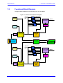
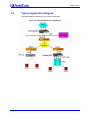


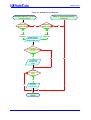


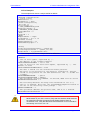
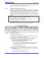

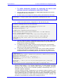


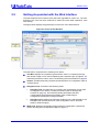

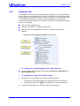
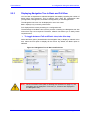
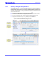

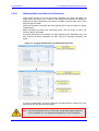

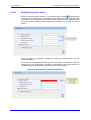
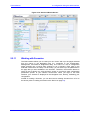
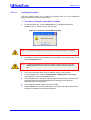
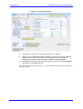
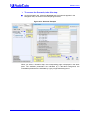
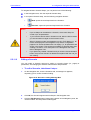
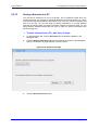


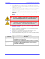

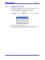
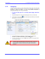


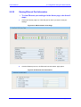
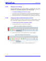

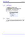
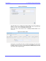

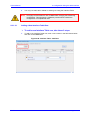
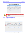
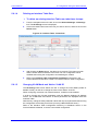

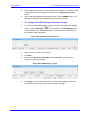

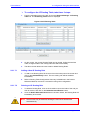
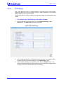
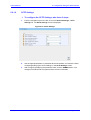

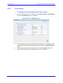
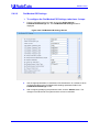


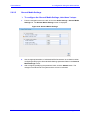
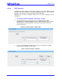

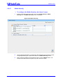

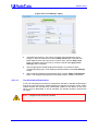
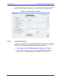
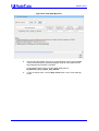
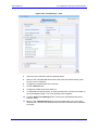

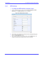
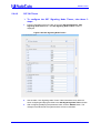
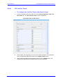
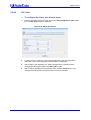
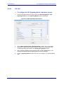
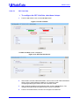
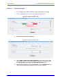
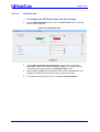
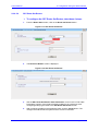


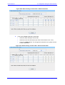
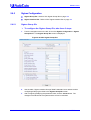
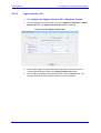
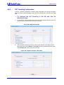
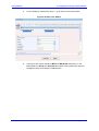

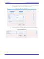
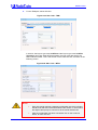

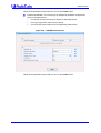
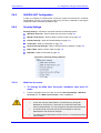

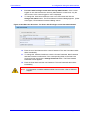
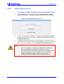
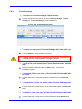


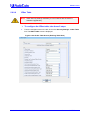
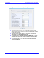
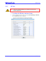

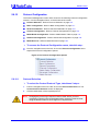
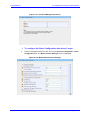

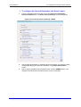
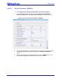


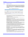

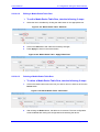
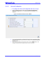
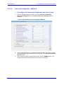
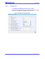
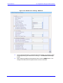


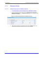

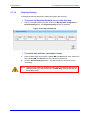
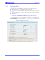
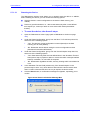
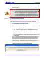


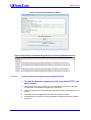

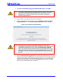
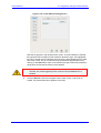
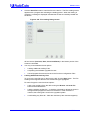
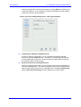


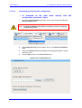
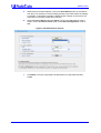
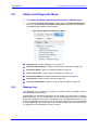
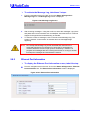
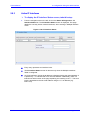


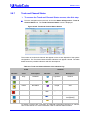

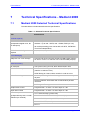

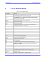
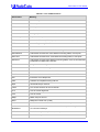
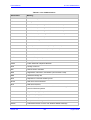


![LTRT-71403 MediaPack MGCP User Manual ver 4[1].](http://vs1.manualzilla.com/store/data/005760883_1-b98cf40cc1cd8cff0fa8bbf345d132db-150x150.png)