1
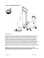
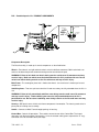
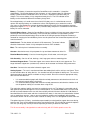
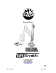
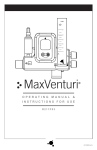
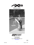
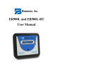
Owner’s Manual
1017 SW Berg Parkway
Canby, OR 97013
Phone: 503.266.2231
Toll Free: 800.824.4387
www.srsmith.com
700-1000 - B
1
June - 2010
TABLE OF CONTENTS
PAL/200-0000/EU - PAL Hi-Lo/250-0000/EU - PAL Spa/275-0000/EU
INTRODUCTION........................................................................................................................................... 3
PRODUCT OVERVIEW ................................................................................................................................ 4
PAL PRODUCT COMPONENTS.................................................................................................................. 5
UNPACKING & ASSEMBLY INSTRUCTIONS............................................................................................. 8
UNPACKING AND ASSEMBLY PROCEDURE FOR THE PAL................................................................... 9
USING THE PAL ..………………………………………………………………………………………………... 11
POSITIONING............................................................................................................................................. 11
TRANSFERRING ...………………………………………………………………………………………………..12
BATTERY CHARGING ............................................................................................................................... 13
STANDARD ACCESSORIES/OPTIONAL ACCESSORIES....................................................................... 14
MAINTENANCE & CLEANSING................................................................................................................. 15
TROUBLE SHOOTING ............................................................................................................................... 15
LONG TERM STORAGE ............................................…………………………………………………………16
WARRANTY INFORMATION ..................................................................................................................... 16
BATTERIES AND BATTERY DISPOSAL ...……………………………………………………………………18
SPECIFICATIONS ...................................................................................................................................... 19
1. Dimensions/Capacity ………………………………………………………………………………………..19
2. Actuator ............................................................................................................................................... 19
3. Motor.................................................................................................................................................... 19
4. Battery ................................................................................................................................................. 19
5. Range of Motion .................................................................................................................................. 19
6. Noise ………………………………………………………………………………………………………...19
7. Materials and Finish ............................................................................................................................ 20
PART LIST .................................................................................................................................................. 20
700-1000 - B
2
June - 2010
INTRODUCTION
The purpose of this document is to provide information relating to the safe operation, care, and
maintenance of the PAL/200-0000/EU - PAL Hi-Lo/250-0000/EU - PAL Spa/275-0000/EU
Intended Lift User:
All of S.R. Smith’s lifts have been designed to assist anyone who has problems entering or exiting a
swimming pool or spa - the only restriction is that the User does not exceed the weight limit of the product
(300 lb/136 kg). It is the responsibility of the lift Owner to ensure that the correct safety procedures have
been put in place and a risk assessment carried out. The unit must be correctly positioned with the
stabilizer arms fully extended and the rear brakes fully applied prior to use. If a User is mentally
challenged or has severe physical disabilities these issues must be taken into account to determine the
number of persons required to complete the transfer onto the seat and the number of persons required to
be in the water, ready to receive the User. The correct stabilizing system (seat belt or stability vest) must
be attached to the seat and fully fastened and used during each transfer.
Our goal is to provide our customers with the most advanced and innovative designs offering exceptional
quality at affordable prices. All of our lifts meet the specifications set forth by the Access Board - ADAAG
2004 (US only), Medical Device Directive, and ISO10535:2006 including repeating the lifting cycle of the
hoist (lift) for a total of 11,000 cycles. The lift system and AC powered battery charger complies with
EN60601-1-2, 2007/03.
US Patent No. 5,790,995
PAL - Portable Aquatic Lift and the PAL logo are registered trademarks of S.R. Smith, LLC.
Model / Product
No.______
Product Name
___________
S.R. Smith, LLC
PO Box 400
1017 SW Berg Parkway
Canby, Oregon 97013 USA
Phone: 503-266-2231
Fax: 503-266-4334
www.srsmith.com
Made in USA
SN S
QNET B.V.
Hommerterweg 286
6436 AM Amstenrade
The Netherlands
[email protected]
[email protected]
24 VDC
700-1000 - B
3
June - 2010
THE PAL - PORTABLE AQUATIC LIFT
Product Overview
The PAL-Portable Aquatic Lift is a portable lift system designed so that individuals with disabilities and
mobility impairments can have universal access to any type of swimming pool or spa. The PAL is
powered by a 24 volt rechargeable battery operated by a screw-driven electronic actuator that provides
the lifting and turning motions. S.R. Smith has designed the safest possible lift system, following all
instructions in the owner’s manual, and all product labels is necessary to achieve safe, reliable and
proper performance of the lift and avoid injury. This design ensures consistent safe operation and
minimizes service problems. The PAL is designed to provide flexibility for aquatic facilities seeking to
provide access to more than one pool or spa, or to accommodate a user’s desire to enter a single pool in
multiple locations. The PAL is available in a Hi-Lo version for facilities with both in-ground pools and
above-ground spas, as well as a Spa version for above-ground pools and spas. The maximum lift
capacity for all PAL models is 300 lb/136 kg. Only persons healthy enough for water activities should use
the PAL. Users should consult with their physician to determine if water activities are appropriate for the
User.
WARNING: The PAL lift is designed to transfer (lift) users from the deck surrounding the
swimming pool/spa into the water and back again. It is not designed to transport users from place
to place. Serious injury can result if the lift is moved while a user is in the seat.
700-1000 - B
4
June - 2010
PAL – Portable Aquatic Lift - PRODUCT COMPONENTS
ACTUATOR
ACTUATOR
ARM
BUSHING
BUSHING
RMT
NYLOCK
NUT
BOLT
BUSHING
Rev.2
10-23-07
Component Description
The Base Assembly is made up of several components as described below:
Wheels - Front wheels are rigid and back wheels swivel to facilitate movement. Both back wheels can
and must be locked to prevent movement during transfer to and from the pool.
WARNING: Failure to lock both rear wheels during transfer could cause lift movement and may
result in injury. Both rear wheels must be locked whenever the lift is positioned for use. Do not
unlock rear wheels during transfer as the lift could move and may result in injury.
Main Frame - The rectangular piece that is fixed to the wheels - the main frame is made up of several
components:
Stabilizing Arms - Two arms pull out to level the lift and must always be fully extended when the lift is in
use.
WARNING: Failure to fully extend both stabilizer arms during transfer could cause lift movement
and may result in injury. Both stabilizing arms must be fully extended whenever the lift is
positioned for use. Do not retract stabilizing arms during transfer as the lift could move and may
result in injury.
Housing - ABS plastic cover shields main frame components from weather. The housing needs to be in
place prior to installing mast assembly.
Handle - Connects to Main Frame through openings in housing.
Control Box - Controls lift operations. Three cables connect to rear of the Control Box. The largest
connector is for the hand control. Connector # 1 is for the actuator cable (green stripe with the “o” ring).
Connector # 2 is for the motor cable (red stripe).
700-1000 - B
5
June - 2010
Battery – The battery is located on top of the Control Box and is removable. It should be
charged daily. Do not allow battery to fully discharge, as it will shorten battery life. Whenever
battery is removed from Control Box or lift is not in use it is important to connect battery to
charger. This ensures battery is fully charged and ready for use. The LCD indicator on the
battery can be checked to determine the battery charge level.
Do not drop battery as it could cause the unit to fail. If battery case is cracked do not use and
replace. Do not place battery on a conductive surface. Placing battery on a conductive surface
may cause a short. Battery has contacts located on bottom of housing. During temperature extremes
beyond the range of 41 F (5 C) to 104 F (40 C) remove battery and place in a controlled environment or
battery life can be shortened.
Console/Battery Cover – Keep the Console/Battery Cover installed at all times to prevent moisture from
collecting on the Control Box and battery. Excessive moisture collection can affect battery and lift
performance and could lead to battery failure and/or the lift failing to operate. Whenever the battery is
removed for charging the Console/Battery Cover must be placed over the Control Box to protect the unit
from the elements.
Hand Control - The four button unit controls all lift movements. The arrows indicate
direction of movement. Control is fully waterproof and meets IP67 standards.
Mast - This vertical piece is bolted to the base assembly.
Actuator - Attached to mast, this part powers the up and down movements of the lift.
Rotation Motor Assembly - Consists of mounting plate, 24-volt motor, and small gear.
Hub Assembly - Consists of hub, bearings, shaft, large gear and mast mounting plate.
Horizontal Support Arms - These two support arms connect the mast to the seat support arm. The
longer horizontal support arm (actuator arm) connects to the actuator and initiates lifting movements.
Seat Arm - Connects the seat to the horizontal support arms.
Seating System – The seat is manufactured from roto-molded plastic with a stainless steel frame. There
are two available forms of safety devices - the standard seat belt and optional stability vest. The seat has
attachment points for both devices and both are easy to attach. Be sure to select the appropriate safety
device for the intended User.
•
•
It is recommended that people with limited or no body movement at or below the waist shall use
the seat belt restraint when using the lift.
It is recommended that people with limited or no body movement at or below the shoulders shall
use the optional stability vest restraint when using the lift.
The seat belt or optional stability vest must be used during each use. The footrest is removable and will
float upwards to prevent damage if the seat is lowered too far. It is recommended that the seat be rinsed
off with fresh water between each use and cleansed daily with a disinfectant solution of 1:100 dilution of
household bleach to fresh water and then rinsed with fresh water. In the event of a contamination incident
such as patient/user excreta - cleanse seat and seatbelt or stability vest immediately with the above
disinfectant solution. Do not use the seat or seatbelt or stability vest if it is damaged or becomes worn out.
The optional armrests (US only - standard on export models) are designed for support when transferring
onto the seat. They can be rotated up out of the way during transfer. If the lift did not include the optional
arm rests (US only) they can be purchased separately and easily installed at a later date.
This lift seat assembly is designed to be used exclusively with S.R. Smith aquatic access lifts.
700-1000 - B
6
June - 2010
Counter Weights - The weights for the lift are located in the bottom of the pallet. Remove the restraining
planks with a screwdriver to gain access.
Each weight is approximately 30 lb/13.6 kg. Use caution when lifting. There are finger holds on each
weight to help handling.
Weights leave the factory in good condition; however, they may have shifted during shipping. Inspect the
weights prior to installation to be sure the paint has not been scratched. Use the touch-up paint supplied
to cover any scratches. The weights are cast iron - if the raw surface is exposed to the elements, it can
rust which could stain the pool deck. Inspect the weight stack monthly for any scratches and touch up as
required. Acrylic spray paint can be used in place of the touch up paint.
Place the weights onto the PAL frame as shown in the diagrams. Stack the weights so the feet on the
bottom of the weight nest into the indentation on top. There are three layers of weights, eight per layer.
With the weights in place, attach the restraining harness to the snaps underneath frame as shown in the
diagrams. Assemble the rest of the PAL according to the instructions that follow.
CAUTION: The restraining harness must be correctly attached to frame. Failure to correctly attach the
restraining harness to frame may result in the weights shifting during use.
700-1000 - B
7
June - 2010
UNPACKING & ASSEMBLY INSTRUCTIONS
REFER TO DIAGRAM (page 5) FOR PARTS IDENTIFICATION.
READ THESE INSTRUCTIONS IN THEIR ENTIRETY BEFORE UNCRATING PAL
Prior to opening pallet, inspect external condition for any visible damage. It is important that any
damage be noted on the Bill of Lading. Immediately notify S.R. Smith or your Authorized Reseller
of missing or damaged parts.
The PAL is shipped on a covered pallet and is VERY HEAVY. You will need the following tools for
unpacking and assembly:
•
•
•
•
3/4” or 19mm socket wrench
9/16” or 14mm socket and 9/16” or 14mm wrench
small flat blade screwdriver
knife or cutters to cut shrink-wrap/bands.
700-1000 - B
8
June - 2010
Unpacking & Assembly Procedure for the PAL – Portable Aquatic Lift
1. Cut open enclosure bag at base of unit - carefully remove plastic.
2. Cut internal bands – remove mast assembly, seat assembly and housing. Lift assembly by mast and
seat arm. Do not lift mast assembly by actuator as this could damage the actuator.
3. Remove accessory box.
4. Remove handle from frame.
5. Remove main frame from pallet. Position main frame close to pallet and lock both rear wheels.
6. Remove bracing from pallet to allow access to counterweights and carefully transfer 24 counterweights
from pallet and attach restraining strap following instructions on page 7.
7. Place housing on frame.
8. Remove 2 lock nuts and washers from mast mounting hub on base assembly.
9. Position mast assembly through housing and attach to studs located on base assembly with lock nuts
and washers. Fully tighten with 3/4” or 19mm socket wrench.
10. Remove plastic from mast assembly. Remove 3/8”(10mm) bolt and nut from actuator arm end.
Following the illustration - attach actuator end to end of actuator arm using the same 3/8”(10mm) bolt and
nut. Fully tighten bolt and nut using 9/16”(14mm) socket and wrench.
11. Remove twist-tie and uncoil actuator cable at bottom of mast.
12. Lift and slide housing part way up mast to gain access to frame area under housing.
13. Run actuator cable along with 24v motor cable across top of weights and insert through hole in rear of
housing near Control Box.
700-1000 - B
9
June - 2010
14. Insert actuator cable (green stripe with the “o” ring) into connector #1 on the Control Box. Make sure
plug is secure.
15. Insert 24v motor cable (red stripe) into connector #2 on the Control Box. Make sure plug is secure.
16. Return housing to normal position and insert handle over mounts.
17. Remove and unwrap hand control from accessory carton. Insert plug into large connector on the
Control Box and hang hand control on handle. Make sure plug is secure.
18. Attach battery to Control Box mounted on housing.
19. Cover Control Box and battery with Console/Battery Cover to protect from moisture.
20. Fully extend both stabilizer bars and fully lock both rear wheels to prevent movement.
21. Check up and down controls for proper operation.
22. Check side to side controls for proper operation.
23. Attach seat assembly with bolt and thumbnut in appropriate hole. For storage, seat can be attached
facing inward for less space.
24. Attach foot rest to seat with bolts and thumbnuts.
700-1000 - B
10
June - 2010
USING THE PAL – Portable Aquatic Lift
Obey all User Instructions listed in the Owners Manual whenever using lift. Obey all Caution,
Warning, Operating Instruction(s) and Labels located on the lift whenever using. It is the
responsibility of the lift Owner to ensure that the correct safety procedures have been put in place
and a risk assessment carried out. If a User is mentally challenged or has severe physical
disabilities these issues must be taken into account to determine the number of persons required
to complete the transfer onto the seat and the number of persons required to be in the water,
ready to receive the User. If the PAL will be used by a disabled person living on their own, a
communication device should be installed in the area of use to call for assistance in the event of
an emergency. Only persons healthy enough for water activities should use the PAL. Users
should consult with their physician to determine if water activities are appropriate for the User.
Keep fingers and hands clear of lift arms during use.
POSITIONING
Four important things to REMEMBER when positioning the PAL for use:
1.
2.
3.
4.
Maintain a firm grip on the handle - use care when positioning the PAL. It is heavy (945 lb/ 429 kg)
Do not use the seat as a hand hold to position the PAL – Only use the handle.
Position the PAL on level ground and in an area that allows plenty of room for transferring to and
from a wheelchair.
Fully extend both stabilizing arms.
Lock both rear wheels.
WARNING: Failure to fully extend both stabilizing arms and to lock both rear wheels could cause
lift movement during transfer and could result in injury. Both stabilizing arms must be fully
extended and both rear wheels must be locked whenever lift is used. Do not retract stabilizing
arms or unlock rear wheels during transfer as the lift could move and may result in injury. The
maximum lift capacity is 300 lb/136 kg. Keep fingers clear of lift arms during use.
PAL Positioning Diagram
700-1000 - B
11
June - 2010
TRANSFERRING
Once the unit is positioned for use with both stabilizing arms fully extended and both rear wheels locked use the following procedure to transfer to the seat and into the water. Only persons healthy enough for
water activities should use the PAL. Users should consult with their physician to determine if water
activities are appropriate for the User:
•
•
•
•
•
•
•
•
•
•
•
•
•
•
•
•
•
Keep fingers and hands clear of lift arms during use.
Rotate seat to either side of lift for best transfer position.
Raise or lower seat to proper transfer height.
Transfer onto seat, ensuring user’s weight is centered on seat. Armrests can be rotated up if
necessary (optional US/standard on export). If user has a wheelchair, keep chair close by for
easy retrieval.
Fasten Seat Belt - thread loose end of belt strap through buckle - pull tight - to close - press latch
down on belt material.
Or fasten optional Stability Vest - Position shoulder straps onto shoulders and attach straps to
clips on bottom panel of the Stability Vest - pull shoulder straps tight.
Raise seat to allow enough legroom for rotation.
Rotate seat to 12:00 position, over water.
Lower seat into pool. The waterproof hand control can remain connected to seat if swimmer is
operating lift.
Unfasten Seat Belt - grasp latch and lift up, pull loose end from latch.
Or unfasten optional Stability Vest - unclip shoulder straps and transfer into water.
When finished, return to seat, ensuring user’s weight is centered on seat.
Raise seat to allow enough legroom for rotation.
Rotate seat to original transfer position.
Raise or lower seat to proper transfer height.
Unfasten Seat Belt or optional Stability Vest.
Transfer off of seat.
WARNING: The PAL lift is designed to transfer (lift) users from the deck surrounding the
swimming pool/spa into the water and back again. It is not designed to transport users from place
to place. Serious injury can result if the lift is moved while a user is in the seat.
IN CASE OF HAND CONTROL FAILURE
Lifting failure - In the event of a lifting failure, there are emergency control buttons built into the control
box. Use a blunt object, like the cap of a ball point pen, to press the appropriate up or down emergency
button located above the LCD Display on the control box.
If the PAL will be used by a disabled person living on their own, a communication device should
be installed in the area of use to call for assistance in the event of an emergency.
700-1000 - B
12
June - 2010
BATTERY CHARGING
Connect the charging unit to the port located on the contact side of the battery. It is not necessary to fully
discharge the battery prior to charging. Battery should be charged daily and cannot be overcharged. It
takes two to four hours to fully charge depending upon battery usage. Do not allow battery to fully
discharge, as it will shorten battery life. Whenever battery is removed from Control Box or lift is not in use
it is important to connect battery to charger. This ensures battery is fully charged and ready for use.
A fully charged battery will provide approximately 30 lifting cycles, depending on the weight of the users.
The battery is fully charged prior to shipping, but should be checked by observing the LCD indicator,
located on the Control Box, prior to use to ensure sufficient charge level.
Do not drop the battery, as it could cause the unit to fail. If the battery case is cracked do not use and
replace. Do not place battery on a conductive surface. Placing battery on a conductive surface may cause
a short. Battery has contacts located on bottom of housing. During temperature extremes beyond the
range of 41 F (5 C) to 104 F (40 C) remove battery and place in a controlled environment or battery life
can be shortened.
Keep the Console/Battery Cover installed at all times to prevent moisture from collecting on the Control
Box and battery. Excessive moisture collection can affect battery and lift performance and could lead to
battery failure and/or the lift failing to operate.
IN CASE OF BATTERY FAILURE
Turning failure - If the lift will not turn electronically, you can remove the housing and loosen the nut
(7/16” – 11mm) on the tension spring located next to the turning motor. This will disengage the gears and
allow the lift to be turned manually.
If the PAL will be used by a disabled person living on their own, a communication device should
be installed in the area of use to call for assistance in the event of an emergency.
BATTERY DISPOSAL
The battery is recyclable and shall be disposed of in accordance with applicable local, state/provincial or
federal/national regulations.
700-1000 - B
13
June - 2010
STANDARD ACCESSORIES/OPTIONAL ACCESSORIES
The following items are included with all pool lift models:
•
•
•
Console/Battery Cover - Protects battery and control unit from exposure to moisture.
Seat Belt Assembly - Nylon water-resistant belt for added security.
Battery/Charger – 24-volt rechargeable battery.
Optional accessories may be purchased for your PAL - Portable Aquatic Lift through your Authorized
Reseller. The following accessories are available:
Stability Vest - P/N 900-2000: Five point restraint for individuals who need higher degree of stability than
provided with standard seat belt.
Total Cover - P/N 920-2000: Made of weather resistant nylon material to keep unit protected from
elements when not in use.
Arm Rest Assembly - P/N 170-1000: Powder coated stainless steel arm rests for increased sense of
security.
Spine Board Attachment - P/N 500-1000: Can be used to convert lift for use with any standard spine
board. (Spine Board not included)
Seat Pad - P/N 890-1000: Waterproof seat pad designed to enhance comfort during transfer.
700-1000 - B
14
June - 2010
MAINTENANCE and CLEANSING
Minimal maintenance will prolong the life of your lift. Keep all electronic components clean and dry. Keep
the Console/Battery Cover installed at all times to prevent moisture from collecting on the Control Box
and battery. Excessive moisture collection can affect battery and lift performance and could lead to
battery failure and/or the lift failing to operate. If the lift is used outdoors, an optional full cover is available
and recommended.
Owners of lifts shall be aware of any applicable local, state/provincial or federal/national regulations
regarding the inspection and or testing of lifts.
The following schedule must be performed to insure proper operation with the Daily items
performed before each use:
Maintenance Performed
Check battery level before each use / Charge battery daily
Daily
Weekly
Monthly
Wipe Control Box and battery connection with a clean dry rag
Examine lift for any damage, loose or missing hardware
Test for normal operation
Spray gear assembly with a heavy-duty rust inhibitor/lubricant
such as LPS 3 - Heavy-Duty Inhibitor
Make sure all cable connections are properly secured
Inspect lift frame, mast, support arm and seat assembly for rust
Inspect weight stack for rust/treat with touch up paint
Cleansing Performed – after each use
Rinse seat and seatbelt/stability vest with fresh water between
each use - Cleanse seat and seatbelt/stability vest with a
disinfectant solution of 1:100 dilution of household bleach to
fresh water and then rinse with fresh water and dry entire lift
daily. In the event of a contamination incident such patient/user
excreta - cleanse seat and seatbelt/stability vest immediately
with the disinfectant solution*
Cleanse all battery connections with a nylon scouring pad
Cleanse all metallic surfaces with a cleaner wax to maintain the
finish of the lift
* When using the disinfection solution avoid direct contact with the skin and eyes. In the event of a
contamination incident - immerse the seat belt or stability vest in the disinfection solution for 10 min. and
then rinse thoroughly with fresh water.
TROUBLE SHOOTING
Be sure the battery is fully charged before troubleshooting.
Lift does not rotate
Does lift raise or lower?
Yes.
1. Check connection to Control Box. Be sure plug is pushed in all the way.
2. Check hand control connection to Control Box for damaged pins.
3. Check connections on terminal block located on frame for loose wires.
700-1000 - B
15
June - 2010
4. Check connection cable for damage.
5. Reverse the motor cables as follows: Locate the area on the Control Box where the
cables are attached. Remove the actuator cable from connector #1 and replace it with the
24v motor cable from connector #2. Activate the up and down buttons on the hand
control. If lift rotates, the problem is likely the hand control. If lift does not rotate, the
problem is likely the 24v motor. If this happens contact your Authorized Reseller or S.R.
Smith for replacement information.
Does lift raise or lower?
No.
1. Check battery charge level.
2. Check battery connection.
3. Use another fully charged battery. If lift continues to not function, replace the Control
Box.
Lift does not Raise or Lower
Does lift rotate?
Yes.
1. Check connection to Control Box. Be sure plug is pushed in all the way.
2. Check hand control connection to Control Box for damaged pins.
3. Check connection cable for damage.
4. Locate Emergency Buttons on top of Control Box. Activate these buttons using a ball
point pen. If lift operates properly, the problem is likely the hand control. If lift does
not operate properly, the problem is likely the actuator.
Does lift rotate?
No.
1. Check battery charge level.
2. Check battery connection.
3. Use another fully charged battery. If lift does not function, replace the Control Box.
LONG-TERM STORAGE
When storing the lift for an extended period of time:
•
•
•
•
Wash seat with disinfection solution and then rinse with fresh water and dry entire lift
Spray gear assembly with a heavy duty rust inhibitor and lubricant such as LPS 3 - Heavy-Duty
Inhibitor
Keep the battery on the charger in a dry temperature controlled area
Cover unit and store in a dry location away from pool chemicals
Questions/Comments - Contact us at 800.824.4387 or 503-266-2231 or [email protected]. For
information regarding Authorized Resellers worldwide visit www.srsmith.com
WARRANTY INFORMATION
S.R. Smith, LLC warrants to the original retail purchaser that products manufactured by S.R. Smith, when properly assembled and
installed in accordance with S.R. Smith’s assembly and installation instructions, and properly used and maintained, shall be free
from defects in material and workmanship for a period of three (3) years from the date of original manufacture except for the
following items: WetDek™ (1 year) and PoolSonix™ (2 years). The original retail purchaser must follow the procedure set forth
below when submitting a warranty claim. S.R. Smith will repair or replace, at its option, the product, and return it to the owner freight
prepaid. Determination of repair or replacement shall be solely at the discretion of S.R. Smith. Aquatic lift systems, components
and batteries have a separate warranty, set forth below.
700-1000 - B
16
June - 2010
All Aquatic Lifting Systems have a three (3) year warranty on the frame, excluding the powder coated paint finish, which may
become scratched with normal use. All electronic and motor components, with the exception of batteries, have a full two (2) year
warranty. Within the warranty period, S.R.Smith will repair or replace any item deemed to be found defective. Lift batteries come
with a one-year pro-rated warranty. During the first 90 days of ownership, batteries will be covered 100%. If a battery failure occurs
between day 91 and day 365, batteries are covered at 50% of the original cost. Normal maintenance and care of the unit, including
charging of the battery when not in use is recommended. Do not store the unit, battery or components near or around chemicals.
The warranty is non-transferable and is subject to the following terms and conditions (View complete S.R. Smith Terms &
Conditions):
S.R. Smith shall not be responsible for the cost of removal or replacement of any defective S.R. Smith product, nor for any other
expenses or for damages which might be incurred in such removal and replacement.
This warranty specifically excludes fading of materials, microbiological staining of diving boards or pool slides and rust or
corrosion of any metallic products or parts. Refer to S.R. Smith care and maintenance instructions for regular
maintenance and cleaning of S.R. Smith Products. Maintenance instructions can be found at www.srsmith.com/care.php.
This warranty relates only to defects in materials and workmanship and does not include damage or failure resulting from other
causes, including, but not limited to Acts of God, misuse or abuse, accident or negligence, fire, improper assembly or installation,
chipping or flaking of powder or vinyl coatings, or ice damage. Damage induced by the improper use of chemicals is not covered by
this warranty. In the event that products are altered or repaired by anyone without the prior written approval of S.R. Smith, all
warranties are void.
IMPORTANT: WEIGHT LIMIT ON DIVING BOARDS, JUMP BOARDS, STANDS, SLIDES, LADDERS AND LADDER STEPS
SHALL BE NOT MORE THAN 250 POUNDS. EXCEPTIONS: FRONTIER IV BOARD AND BASE NOT MORE THAN 400 POUNDS.
TURBOTWISTER AND TYPHOON SLIDES NOT MORE THAN 275 POUNDS. CYCLONE SLIDE NOT MORE THAN 175
POUNDS. VORTEX SLIDES NOT MORE THAN 325 POUNDS.
S.R. Smith shall not be liable for any consequential, special or incidental damages, including, but not limited to any damages for loss
of use of pools or injury to person or property, and any claims therefore are hereby specifically disclaimed and excluded. Some
states do not allow the exclusion or limitation of incidental, special or consequential damages, so the above limitation or exclusion
may not apply to you. This warranty gives you specific legal rights and you may also have other rights, which may vary from state to
state. The warranty is extended to, and enforceable only by the original retail purchaser.
If any S.R. Smith products fail during the warranty period as a result of a defect in material or workmanship covered by this
warranty, the original retail purchaser must notify S.R. Smith via www.srsmith.com/warranty.php. This notice from the original retail
purchaser must contain all pertinent product information as outlined in the warranty claim form. S.R. Smith will determine if the
product is to be returned to the factory or will ask that ( 1 ) the defective area and ( 2 ) the part of the product stamped with the serial
number be removed and returned. Product pieces must be cleaned and returned freight prepaid to S.R. Smith’s facility at either
1017 SW Berg Parkway, Canby, OR 97013 or 105 Challenger Drive, Portland, TN 37418 as determined by S.R. Smith.
THE WARRANTY SET FORTH HEREIN IS IN LIEU OF ALL OTHER WARRANTIES, EXPRESSED OR IMPLIED, WHICH ARE
HEREBY DISCLAIMED AND EXCLUDED, INCLUDING WITHOUT LIMITATION ANY WARRANTY OF MERCHANTABILITY OR
FITNESS FOR A PARTICULAR PURPOSE OR USE.
THE SOLE AND EXCLUSIVE REMEDIES FOR BREACH OF ANY AND ALL WARRANTIES WITH RESPECT TO THE
PRODUCTS SHALL BE LIMITED TO REPAIR OR REPLACEMENT AT S.R. SMITH’S DESIGNATED FACTORY OR IN PLACE AT
S.R. SMITH’S OPTION. IN NO EVENT SHALL S.R. SMITH’S LIABILITY EXCEED THE ENTIRE AMOUNT PAID TO S.R. SMITH
BY THE ORIGINAL PURCHASER FOR THE FAILED OR DEFECTIVE PRODUCT.
IN NO EVENT SHALL S.R. SMITH BE LIABLE FOR ANY INCIDENTAL, CONSEQUENTIAL, SPECIAL, INDIRECT, PUNITIVE OR
EXEMPLARY DAMAGES OR LOST PROFITS FROM ANY BREACH OF THIS LIMITED WARRANTY OR OTHERWISE.
No representative of S.R. Smith, nor any of its agents, distributors or dealers has any authority to alter in any manner the terms of
this warranty and S.R. Smith is not responsible for any undertaking, representation or warranty made by any other person beyond
the warranty expressly set forth in this warranty.
Warranty Procedures
The S.R. Smith warranty becomes effective on the date of manufacture.
700-1000 - B
17
June - 2010
To initiate a warranty replacement, Please follow the process outlined below.
1. Take photos of the damaged product.
a) The photo must include the entire unit (i.e. board and stand or slide from a distance).
b) Also include one photo or more of the damaged area.
2. Remove the serial # sticker from the product.
a) S.R. Smith provides a serial # for every board, stand, slide and rail product we produce. The
sticker with the serial number for our boards, stands and slides is a silver, 1" long rectangular
sticker found on the side or bottom of the item. The serial # sticker for our rail products is clear
and 2" long. It will be found on the inside of the topmost curve.
3. Attach the photos and the serial # sticker to a written request for replacement under the
S.R. Smith warranty. Please include the following information:
a) Product name and description. (i.e.: board length/color, curve direction of slide, etc.)
b) Date of purchase and/or date of installation.
c) Description of damage.
d) Shipping address with a contact name and phone number.
4. Return to us by mail or email at www.srsmith.com/warrarnty.php the photos, serial #
sticker and your written request to:
S.R. Smith, LLC
PO Box 400
1017 SW Berg Pkwy
Canby, OR 97013
Attn: Warranty Specialist
**Please Note: Missing information will result in a processing delay and possibly denial of your claim.
Should you have any questions regarding this process, please contact
S.R. Smith's Warranty specialist at 800.824.4387 or 503-266-2231 or email [email protected]
Batteries
All batteries are inspected prior to shipment and should be free from defect. See warranty policy
regarding battery replacement due to defect. Batteries have a normal lifespan of between 2-3 years,
depending on use and care.
Battery should be charged daily. Do not allow battery to fully discharge, as it will shorten battery life.
Whenever battery is removed from Control Box or lift is not in use it is important to connect battery to
charger. This ensures battery is fully charged and ready for use.
Do not drop the battery, as it could cause the unit to fail. If the battery case is cracked do not use and
replace. Battery has contacts located on the bottom of the housing. Do not place on a conductive surface
that can cause a short. During temperature extremes beyond the range of 41 F (5 C) to 104 F (40 C)
remove battery and place in a controlled environment or battery life can be shortened.
Keep the Console/Battery Cover installed at all times to prevent moisture from collecting on the Control
Box and battery. Excessive moisture collection can affect battery and lift performance and could lead to
battery failure and/or the lift failing to operate.
BATTERY DISPOSAL
The battery is recyclable and shall be disposed of in accordance with applicable local, state/provincial or
federal/national regulations.
700-1000 - B
18
June - 2010
SPECIFICATIONS
PAL/200-0000/EU - PAL Hi-Lo/250-0000/EU - PAL Spa/275-0000/EU
1. Dimensions/Capacity
Overall Height
Base Dimensions Height
Overall Length with Footrest
Overall Length without Footrest
Overall Length in Stored position
Total Weight
Power
Battery Life (Charged)
Lifting Capacity
Seat Width
66”/167.6cm
22.5”/55.1cm, length. 37.5”/95.2cm, width 27.5”/69.8cm
106”/269.2cm (fully extended)
91”/231.1cm (fully extended)
61”/154.9cm (fully raised)
945 lb/429 kg
24V DC
30 cycles (approximate)
300 lb/136 kg
18.5”/47cm
2. Actuator
Lifting
Max. Thrust
Voltage
Max. Amp
Max. Speed
Screw Type Mechanical Actuator
1680 lb/7472N
24V DC5”/12.7cm Total Lock Swivel
9
0.59 inch/sec./1.49cm/sec.
3. Motor
Rotation
Gearing Ratio
24 VDC 13 RMP
9:1
4. Battery
Power
Temperature Range
24 VDC, IP65 Gel Lead Acid
41 F (5 C) to 104 F (40 C)
5. Range of Motion
Lifting
Seat Depth
6. Noise
700-1000 - B
Variable to configure to each pool. 44”- 58”/112cm –
147cm total travel from highest to lowest point w/
standard actuator.
18”-20”/46cm – 51cm below water line.
Rotation: 240º
Noise level below 50 dB (A), measured according
to DS/EN ISO 3746”
19
June - 2010
7. Materials and Finish
Frame
Handle
Housing
Casters
Front
Powder Coated Stainless Steel
Powder Coated Aluminum
Vacuum Formed ABS Plastic
Ball Bearing, Stainless Steel, 5”/12.7cm Fixed,
Polyurethane Tread
Ball Bearing, Stainless Steel, 5”/12.7cm Total Lock
Swivel, Polyurethane Tread
Powder Coated Aluminum
Powder Coated, Stainless Steel
Rear
Arms
Mast
Seat Assembly
Seat: Roto-Molded Plastic
Frame: Powder Coated Stainless Steel
PART LIST
Part Number
100-5000A
100-1000A
100-2000
100-3500
100-4000A
120-1100
800-5065
130-1000
120-1000
150-1100A
150-1200A
150-1300A
150-1400
160-1000A
160-1300A
200-1000
200-2000
200-3000
110-3100
200-5000
200-4100
150-2100A
160-2000
150-2200A
150-2300A
150-2400A
700-1000 - B
Description
LA34 Actuator
Control Box
Battery
Battery Charger
Hand Control
24v Motor
Small Gear
Hub Assembly
Motor Mount Assembly
Mast Assembly
Actuator Arm
Support Arm
Seat Arm
Seat Assembly
Foot Rest
PAL Main Frame Assembly
Rigid Caster
Swivel Caster
Cast Iron Weight Plates
PAL Housing Assembly
Stabilizer Assembly
Hi/Lo Mast Assembly
Hi/Lo Seat Assembly
Hi/Lo Actuator Arm
Hi/Lo Tension Arm
Hi/Lo Seat Assembly
20
June - 2010