1
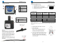
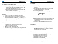
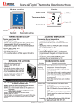
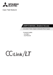
ER900L and ER900L-RT
User Manual
ER900L Recorder
ER900L Recorder
Braemar Limited Warranty
Braemar products are warranted to be free from manufacturing and material
defects for a period of one (1) year from the date of shipment from Braemar to
the original purchaser.
Excluded from this warranty are expendable supply items including, but not
This page intentionally left blank.
limited to, electrodes, lead wires, patient cables and batteries. This warranty
does not apply to any product which Braemar determines has been modified or
damaged by the customer.
Except for the express warranties stated above, Braemar disclaims all warranties
including implied warranties of merchantability and fitness. The stated express
warranties are in lieu of all obligations of liabilities on the part of Braemar for
damages, including but not limited to, special indirect or consequential, arising
out of or in connection with the use or performance of Braemar products.
Any action for breach of warranty shall be commenced within one (1) year of
said breach or be forever barred. Any repairs made to the product which are not
covered by the warranty shall be billed to the customer.
Document Number: 600-0634-00
Revision: B
Date: Sept 2007
1
2
ER900L Recorder
Table of Contents
Overview..................................................................................... 4
Precautions.................................................................................. 4
Setup: .......................................................................................... 4
Misc Notes: ................................................................................. 7
To Record: .................................................................................. 7
To Send Events: .......................................................................... 8
ER900L Recorder
Overview
The ER900L and ER900L-RT are AAMI EC38 compliant type 3 event
recorders intended for ambulatory recording of ECG data from integral
electrodes connected to the patient. They are battery operated, solid state,
looping event recorders designed to record symptomatic heart arrhythmias.
Event recording is activated by the patient via large event button. Both
event monitors provide up to 8 minutes of total recording time and will
operate as a simple looping event recorder for a minimum of 30 days with a
single AAA Alkaline battery. Selectable parameters include pre-event time,
post-event time, audible operation, and real time ECG for the ER900L-RT.
Once an event is recorded, patients may transmit their ECG
transtelephonically.
To Erase Events: ......................................................................... 8
Sound Quick Reference and Troubleshooting ............................ 9
Cleaning .................................................................................... 11
Service....................................................................................... 11
Service Items and Accessories.................................................. 11
Equipment Symbols .................................................................. 12
Specifications............................................................................ 13
Electromagnetic Emissions....................................................... 14
Precautions
A. Patient leads must be removed from electrodes before defibrillation.
B. Observe local laws for disposal of alkaline batteries.
C. Do not leave the batteries in the recorder when it is not in use. Damage
from corrosion could result.
D. Patient should be instructed to avoid close proximity to heavy electrical
equipment or other sources of electromagnetic interference.
E. Use of rechargeable batteries is not recommended.
F. Do not use cellular or VOIP phone to transmit patient data.
G. Recorder is not for infant use.
H. Keep lanyard away from objects that may become entangled with it
and become a choking hazard.
Electromagnetic Immunity........................................................ 14
Recommended Separation Distances........................................ 16
Additional equipment classification information as required in EN 60601-1
A. EQUIPMENT not suitable for use in the presence of a FLAMMABLE
ANAESTHETIC MIXTURE WITH AIR of WITH OXYGEN OR
NITROUS OXIDE
B. IPX0 Ordinary Equipment (enclosed equipment without protection
against ingress of water)
C. Internally Powered Equipment
D. Mode of Operation - Continuous Operation
Caution: U.S. Federal law restricts this device to sale by or
on the order of a physician.
3
4
ER900L Recorder
Monitor Components:
Front View
A
B
C
D
Record Button
Speaker Hole
Memory Full
Indicator
Patient Cable
ER900L Recorder
Setup:
Recorder Setup Quick Overview:
Switch layout viewed
1. Set switches for recorder.
through the battery area.
2. Snap patient cable ends to electrodes.
3. Adhere electrodes to you as in Figure 1.
4. Connect other end of patient cable to the recorder.
5. Install battery and close door.
1. Setting switches:
Max. number
Length of
of events
Pre/Post time
4
45/15 sec
4
30/30 sec (default)
4
60/30 sec
4
60/60 sec
Switch 1
Switch 2
UP
UP
DOWN
DOWN
UP
DOWN
UP
DOWN
Back View
A
B
Belt clip in the up position
to clip on lanyard.
Battery compartement
Push Cord Lock
here to release
Lanyard:
Slip the lanyard over your head with the
cord lock to the back of your neck. Adjust
as necessary by depressing the cord lock
and pulling on the ribbon behind your neck
to a level of comfort. To remove lanyard,
depress the cord lock and gently pull down
on the lanyard in front of you.
Caution: Do Not Yank on the lanyard, this
will cause the cord to slip under the locking
mechanism.
5
Cord
Lock
Finger
Pull
Switch 3
UP
DOWN
Trans Speed
3X (default)
1X
Switch 4*
Real Time ECG (15 sec)
UP
ON
DOWN
OFF
* Feature only available on ER900L-RT
NOTE: Changing switch 1 or 2 will cause the recorder to erase all events in
memory when a battery is inserted. Switches 3 and 4 do not affect events stored
in memory.
2.
Snap the patient cable ends to electrodes.
3.
Electrode Hookup:
Figure 1 indicates a typical placement of the
electrodes. The actual placement will be
determined by the physician instructions.
4.
Connect the round end of the patient cable to
the recorder. The connection will have a firm
snap when completely inserted. Three quick
beeps and two rising tones will sound indicating
a good ECG signal.
6
Figure 1
ER900L Recorder
5.
Install a AAA battery and close the door.
The recorder will beep once and then sound a rising tone upon startup. If
events are stored, a phone ring will also sound.
A. If Switch 1 or 2 are changed, the recorder will sound three very
quick beeps (less than 1 second total) and then a rising tone. This
indicates that events in memory have been erased.
B. To open the battery door, push down the inside center edge of the
battery door. It will open automatically.
C. If the recorder sounds three beeps, 1.5 sec long that repeats every 5
seconds, the battery is low. Install a fresh battery.
Misc Notes:
A. Use the cap from a ball point pen to change the switch settings.
B. The belt clip can be used as a belt clip or a lanyard. To use as a belt
clip, insert it into the back slot from the bottom. To use the belt clip as
a lanyard, insert it into the back slot from the top and clip the lanyard
through the hole on the end of the belt clip. Refer to the Monitor
Components section for an example.
C. Real-time ECG is transmitted before stored events.
ER900L Recorder
To Send Events:
1. Set the Monitor on a flat surface face up.
2. Call the receiving center.
A. Cellular or VOIP phones do not work for the transmission.
B. The patient must remain connected to the recorder to transmit real
time ECG.
C. The patient may remain connected to the recorder during sending
and will not affect the transmission of stored events.
3. Follow receiving center instructions.
4. When instructed, place the telephone mouthpiece (microphone) over
the recorder speaker hole.
5.
6.
To Record:
1. Push the RECORD button for two seconds.
A. A short beep will sound when the recording is started.
B. If no beep is heard, mute is turned on.
2. When done recording, a phone ring will sound.
3. There isn’t any way to stop a recording once it has started. Remain still
but continue breathing at a normal rate during a recording.
Push the SEND button for two seconds. The recorder will produce
tones to transmit the data.
A. The recorder will send 15 seconds of real-time ECG data if
switch 4* is UP and then send all stored events in memory.
B. Pushing the SEND button for two seconds during transmission will
abort the transmission. Pushing the SEND button again will resend the recording
C. A falling tone will sound when the transmission is complete.
Follow additional instructions from the receiving center as required.
To Erase Events:
Push the SEND and RECORD buttons simultaneously for three seconds.
The recorder will beep once when all events are erased.
A. The recorder will also automatically erase previously recorded
events before capturing a new event. This occurs when the
RECORD button is pushed for two seconds after all events have
been successfully sent to receiving center.
To Mute Sound:
Mute will silence the recorder except when sending events.
Push the MUTE button for two seconds to change the mute setting.
A. A single beep will sound when entering mute.
B. A double beep will sound when leaving mute.
C. Mute defaults off when a battery is inserted.
D. Mute defaults off after sending events.
E. The recorder will produce a phone ring sound every five minutes
when full, even if mute is active.
* Switch 4 and real time ECG are only available on the ER900L-RT model.
7
8
ER900L Recorder
Sound Quick Reference and Troubleshooting
Symptom
Phone ring sound at
startup
Phone ring sound when
RECORD button is pushed
Phone ring sound at end of
recording.
Phone ring sound every
hour
Phone ring sound every 5
minutes
Will not record
No phone ring at end of
recording
Siren (alternating) tone
while recording
Siren (alternating) tone in
event memory when
sending events
Three quick beeps and two
rising tones after patient
cable insertion.
Good ECG signal sound is
not present when inserting
the patient cable
Three beeps, 1.5 sec long that
repeats every 5 seconds when
inserting battery
Three beeps, 1.5 sec long that
repeats every 5 minutes while
powered on.
Three very quick beeps,
less than 1 sec. at startup
followed by a rising tone.
Recommended Solution
An event is already stored in memory at start up.
Memory is full, follow instructions To Send and To
Erase Events.
Memory full phone ring overrides the mute option.
Follow instructions To Send and To Erase Events.
Recorder has event(s) to be transmitted to the receiving
center.
Memory is full, follow instructions To Send and To
Erase Events.
Ensure RECORD button is held for two seconds.
Mute is turned on. The recorder is recording but a beep
will not signal the start of recording.
Phone ring sound and Memory Full indicator is lit.
Follow instructions To Send and To Erase Events.
Mute is turned on which mutes most sounds.
ER900L Recorder
Symptom
Very quick (less than ½
sec) two tone sound every
five minutes
Constant beep of same
tone.
No information received
by receiving center
Noise artifact on recorded
ECG at receiving center
All or groups of
timestamps for recordings
are the same.
Cannot erase stored
events.
There is not a good connection. Check that
electrodes/leads have a good connection to patient and
cable is plugged into recorder.
The recorder places alternating square wave in preevent time when good QRS is not available.
Indicates a good ECG signal is present.
Full indicator stays lit
during sending of events
Recommended Solution
Lead Loss detected. Check that electrodes/leads have a
good connection to patient and cable is plugged into
recorder.
Startup self test fail. Most likely a button was pushed
during battery insertion. Reinsert battery. If beeping
continues, call Customer Service.
Make sure mouthpiece of phone is directly over
Monitor speaker
Mouthpiece of phone must be close to the Monitor
speaker hole.
Check telephone connection. Listen to phone line
before sending event(s) to ensure there is no noise.
Have patient call back and send ECG again.
Have patient try another phone.
If the inadvertent loss of power occurs, all the
timestamps in the FSK will reset to the time the unit
powered back up. Subsequent recordings will have
time stamps relative to the power up time.
Push the SEND and RECORD buttons simultaneously
for three seconds. The recorder will beep once when
all events are erased.
Flip switch 1 or 2 and reinstall the battery. Monitor
will produce three very quick beeps, less than 1 sec.
long at startup followed by a rising tone which
indicates all events are erased.
The Full indicator stays in whatever state it is when the
sending of events begins. It just happened to be lit
when transmission started.
Ensure patient electrodes/leads are connected to patient
properly. Is the Patient Cable damaged in some way?
Ensure Patient Cable is inserted completely into the
recorder.
Battery is low. Replace battery and/or clean battery
contacts.
Battery has become low during operation. Replace
battery and/or clean battery contacts.
Indicates Switch 1 or 2 has changed position since last
startup. All events in memory have been erased.
9
10
ER900L Recorder
ER900L Recorder
Service and Maintenance
Cleaning
Remove the battery before cleaning the recorder. Clean the battery
terminals with a soft dry cloth. Dampen a soft cloth with mild detergent
and water to clean the recorder, lead wires, and belt clip. Be careful to keep
liquids from entering the speaker hole.
Equipment Symbols
Symbol
Description
Type B Applied Part
Consult manual.
Remove any adhesives from the patient lead wires with an adhesive tape
remover solution or swab. Use a mild disinfectant. Do not use alcohol or
acetone on the lead wires since they could stiffen and the insulating plastic
could crack.
Service
If there is a problem with the recorder, review the troubleshooting section of
this manual. If additional assistance is required contact customer support via
phone, Fax or E-mail on the next page. Call customer support before
returning a recorder to make shipping arrangements.
A. Note there isn’t any preventative inspection or maintenance that
can be performed by the end user.
SN
Serial Number
0086
Complies with the Medical Device Directive of the
European Union.
Waste Electrical and Electronic Equipment (WEEE)
It is the responsibility of the end user to dispose of
this equipment at a designated collection point for
recycling.
Year of Manufacture
Manufacturer:
Braemar, Inc.
1285 Corporate Center Drive, Suite 150
Eagan, MN 55121 USA
Service Items and Accessories
Description
Patient lead, 1 channel
Lanyard (Necklace)
Belt clip
Operator manual (IFU)
AAA I.E.C. LR03 Alkaline Battery
Part Number
350-0274-00
350-0279-00
100-1811-001
600-0634-00
200-2492-001
Phone:
Fax:
E-mail:
Web:
800.328.2719
651.286.8620
651.286.8630
[email protected]
http://www.braemarinc.com
Contact Braemar for further technical information.
Authorized European Rep:
QNET BV
Hommerterweg 286
6436 AM Amstenrade
The Netherlands
11
12
ER900L Recorder
Specifications
Functional
ER900L
ER900L-RT
Max Number of events
Sample rate
User interface
Memory
Max event time
Max total record time
Type
Data retention
Physical
Dimensions
ER900L Recorder
Electromagnetic Emissions
1 channel only
1 channel only
4
256 samples per second
Sound and light
2 minutes
8.5 minutes
Flash
Non-volatile
Weight with batteries
Enclosure
Operating position
2.5"x 2.25"x .78"
(63mm x 58mm x 20mm)
2 oz
Molded plastic
Any orientation
Electrical
Input impedance
CMR ratio
AC signal range
Resolution
Frequency response
10M min.
60dB min
+/- 3mV
23uV (8bits)
.05Hz to 35Hz
Environmental
Operating temperature
Non-operating temperature
Operating humidity
Non-Operating humidity
0°C to +45°C
-20°C to +65°C
10% to 95% (non-condensing)
5% to 95%
Emissions test Compliance
RF emissions Group 1
CISPR 11
RF emissions Class B
CISPR 11
Electromagnetic
environment - guidance
The ER900L uses RF energy
only for its internal function.
Therefore, its RF emissions are
very low and are not likely to
cause any interference in nearby
electronic equipment.
The ER900L is suitable for use
in all establishments, including
domestic establishments and
those directly connected to the
public low-voltage power supply
network that supplies buildings
used for domestic purposes.
Electromagnetic Immunity
Immunity test
IEC 60601
test level
Compliance
level
Electrostatic
±6 kV contact ±6 kV contact Floors should be wood,
discharge (ESD) ±8 kV air
±8 kV air
concrete or ceramic tile. If
IEC 61000-4-2
floors are covered with
synthetic material, the
relative humidity should be
at least 30%.
Power
3 A/m
3 A/m
Power frequency magnetic
frequency
fields should be at levels
(50/60 Hz)
characteristic of a typical
magnetic field
location in a typical
IEC 61000-4-8
commercial or hospital
environment.
Transtelephonic Transmission
Transmit carrier
1900Hz
Carrier deviation
100Hz/mV
Battery
Type
Life
Warranty
1.5V, AAA Alkaline IEC-LR3
30 days min. during looping recording
Remove battery during storage
12 months from shipment
13
Electromagnetic environment
- guidance
14
ER900L Recorder
ER900L Recorder
Recommended Separation Distances
Refer to the following table for recommended separation distances between the
ER900L and portable and mobile RF communications equipment.
The ER900L is intended for use in an electromagnetic environment in which
radiated RF disturbances are controlled. The user of the ER900L can help
prevent electromagnetic interference by maintaining a minimum distance
between portable and mobile RF communications equipment (transmitters) and
the ER900L as recommended below, according to the maximum output power
of the communications equipment.
Rated maximum output
power of transmitter
W
Separation distance according to
frequency of transmitter
150 kHz
80 MHz
800 MHz
to 80 MHz to 800 MHz to 2,5 GHz
d = 1.2 √ P d = 1.2 √ P
d = 2.3 √ P
0,01
0,12
0,12
0,23
0,1
0,38
0,38
0,73
1
1,2
1,2
2,3
10
3,8
3,8
7,3
100
12
12
23
For transmitters rated at a maximum output power not listed
above, the recommended separation distance d in metres (m)
can be estimated using the equation applicable to the frequency
of the transmitter, where P is the maximum output power
rating of the transmitter in watts (W) according to the
transmitter manufacturer.
NOTE1: At 80 MHz and 800 MHz, the separation distance for
the higher frequency range applies.
NOTE 2: These guidelines may not apply in all situations.
Electromagnetic propagation is affected by absorption and
reflection from structures, objects and people.
15
16
Braemar Inc.
Phone: 800.328.2719
1285 Corporate Center Drive, Suite 150
Fax: 651.286.8630
Eagan, MN 55121 USA
E-Mail: [email protected]
Copyright 2007, Braemar Inc. All rights reserved