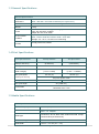
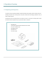
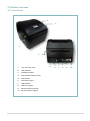
1
DA200/ DA300 Series Direct Thermal Bar Code Printer USER’S MANUAL Copyright Information © 2015 TSC Auto ID Technology Co., Ltd. The copyright in this manual, the software and firmware in the printer described therein are owned by TSC Auto ID Technology Co., Ltd, All rights reserved. CG Triumvirate is a trademark of Agfa Corporation. CG Triumvirate Bold Condensed font is under license from the Monotype Corporation. Windows is a registered trademark of Microsoft Corporation. All other trademarks are the property of their respective owners. Information in this document is subject to change without notice and does not represent a commitment on the part of TSC Auto ID Technology Co. No part of this manual may be reproduced or transmitted in any form or by any means, for any purpose other than the purchaser’s personal use, without the expressed written permission of TSC Auto ID Technology Co. Agency Compliance and Approvals EN 55022, Class A EN 55024 EN 60950-1 This is a class A product. In a domestic environment this product may cause radio interference in which case the user may be required to take adequate measures. FCC part 15B, Class A ICES-003, Class A This equipment has been tested and found to comply with the limits for a Class A digital device, pursuant to Part 15 of the FCC Rules. These limits are designed to provide reasonable protection against harmful interference when the equipment is operated in a commercial environment. This equipment generates, uses, and can radiate radio frequency energy and, if not installed and used in accordance with the manufacturer’s instruction manual, may cause harmful interference with radio communications. Operation of this equipment in a residential area is likely to cause harmful interference, in which case you will be required to correct the interference at your own expense. This Class A digital apparatus complies with Canadian ICES-003. Cet appareil numérique de la classe A est conform à la norme NMB-003 du Canada. AS/NZS CISPR 22, Class A GB 4943.1 GB 9254, Class A GB 17625.1 此为 A 级产品,在生活环境中,该产品可能会造成无线电干扰, 在这种情况下,可能需要用户对干扰采取切实可行的措施。 Energy Star for Imaging Equipment Version 2.0 KN 22 Class A / KN 24 A 급 기기 (업무용 방송통신기자재) 이 기기는 업무용(A 급) 전자파적합기기로서 판매자 또는 사용자는 이 점을 주의하시기 바라며, 가정외의 지역에서 사용하는 것을 목적으로 합니다. BIS 13252 (Part 1) Wichtige Sicherheits-Hinweise 1. Bitte lesen Sie diese Hinweis sorgfältig durch. 2. Heben Sie diese Anleitung fűr den späteren Gebrauch auf. 3. Vor jedem Reinigen ist das Gerät vom Stromentz zu trennen. Verwenden Sie keine Flüssig-oder Aerosolreiniger. Am besten eignet sich ein angefeuchtetes Tuch zur Reinigung. - ii - 4. Die Netzanschluß -Steckdose soll nahe dem Gerät angebracht und leicht zugänglich sein. 5. Das Gerät ist vor Feuchtigkeit zu schűtzen. 6. Bei der Aufstellung des Gerätes ist auf sicheren Stand zu achten. Ein Kippen oder Fallen könnte Beschädigungen hervorrufen. 7. Beachten Sie beim Anschluß ans Stromnetz die Anschluß werte. 8. Dieses Gerät kann bis zu einer Auß entemperatur von maximal 40℃ betrieben werden. CAUTION : Risk of explosion if battery is replaced by an incorrect type. Dispose of used batteries according to the instructions. “VORSICHT” Explosionsgefahr bei unsachgemäß en Austaush der Batterie. Ersatz nur durch denselben oder einem vom Hersteller empfohlenem ähnlichen Typ. Entsorgung gebrauchter Batterien nach Angabren des Herstellers. CAUTION : Any changes or modifications not expressly approved by the grantee of this device could void the user's authority to operate the equipment. CAUTION : HAZARDOUS MOVING PARTS, KEEP FINGER AND OTHER BODY PARTS AWAY. - iii - Contents 1. Introduction ......................................................................................................................................... 1 1.1 Product Introduction ..................................................................................................................... 1 1.2 Product Features .......................................................................................................................... 2 1.2.1 Printer Standard Features ................................................................................................ 2 1.2.2 Printer Optional Features ................................................................................................. 3 1.3 General Specifications ................................................................................................................. 5 1.4 Print Specifications ....................................................................................................................... 5 1.5 Media Specifications .................................................................................................................... 5 2. Operations Overview .......................................................................................................................... 7 2.1 Unpacking and Inspection ............................................................................................................ 7 2.2 Printer Overview ........................................................................................................................... 8 2.2.1 Front & rear ........................................................................................................................ 8 2.2.2 Interior View ....................................................................................................................... 9 2.3 LED and Button Function ........................................................................................................... 10 2.3.1 LED Indication ................................................................................................................. 10 2.3.2 Regular Button Function ................................................................................................ 10 3. Setup ................................................................................................................................................ 11 3.1 Setting up the Printer .................................................................................................................. 11 3.2 Loading the Media ...................................................................................................................... 12 3.2.1 Loading the Roll Labels ................................................................................................. 12 3.2.2 Loading External Media .................................................................................................. 14 3.2.3 Loading Media in Peel-off Mode (Option) ..................................................................... 16 3.2.4 Loading Media in Cutter Mode (Option)........................................................................ 17 3.2.5 Loading Media in Linerless Cutter Mode (Option) ....................................................... 18 3.3 Install the Adapter for 1.5” Paper Core (Option) ........................................................................ 19 4. Power-on Utilities.............................................................................................................................. 20 4.1 Gap/Black Mark Sensor Calibration ........................................................................................... 21 4.2 Gap/Black Mark Calibration, Self-test and Dump Mode ............................................................ 22 4.2.1 Self-test ............................................................................................................................ 23 4.2.2 Dump mode ..................................................................................................................... 25 4.3 Printer Initialization ..................................................................................................................... 26 4.4 Set Black Mark Sensor as Media Sensor and Calibrate the Black Mark Sensor ..................... 27 4.5 Set Gap Sensor as Media Sensor and Calibrate the Gap Sensor ........................................... 27 - iv - 4.6 Skip AUTO.BAS ........................................................................................................................ 28 5. Diagnostic Tool ................................................................................................................................. 29 5.1 Start the Diagnostic Tool ............................................................................................................ 29 5.2 Printer Function .......................................................................................................................... 30 5.3 Setting Ethernet by Diagnostic Tool (Option) ............................................................................. 31 5.3.1 Using USB interface to setup Ethernet interface ......................................................... 31 5.3.2 Using RS-232 interface to setup Ethernet interface .................................................... 32 5.3.3 Using Ethernet interface to setup Ethernet interface.................................................. 33 6. Troubleshooting ................................................................................................................................ 36 6.1 LED Status ................................................................................................................................. 36 6.2 Print Problem .............................................................................................................................. 37 7. Maintenance ..................................................................................................................................... 38 Revise History ....................................................................................................................................... 39 -v- 1. Introduction 1.1 Product Introduction Thank you very much for purchasing TSC bar code printer. The DA200 Series of direct thermal desktop printers are ideal for a wide variety of applications including product marking, point of sale, retail, small office, shipping labels, and other labeling and tag applications at the best price anywhere. The DA200 Series is a perfect combination of affordability with a durable and reliable design. With a cost that can’t be beat, the DA200 series offers both 203 and 300 dots per inch print resolution with printing speeds up to a fast 5 inches per second. The large 60 watt power supply produces high quality printed labels, even at its fastest print speeds. For easy loading, the DA200 employs a user-friendly double-wall clamshell design with a large five-inch (outside diameter) center-biased media bay. The spring-loaded label roll holder makes loading simple. Topof-form sensing – by gap, black mark, or notch – is standard. The printer also comes with a head-open sensor. The DA200 has plenty of memory with 128 MB Flash & 64 MB SDRAM that can be used for easy storage of fonts, international character sets and graphics, and it supports, “right out of the box,” a fully compatible set of ® ® standard industry emulations, including Line Mode, Eltron and Zebra languages, making it easy to replace old installed hardware. To print label formats, please refer to the instructions provided with your labeling software; if you need to write the custom programs, please refer to the TSPL/TSPL2 programming manual that can be found on the accessories CD-ROM or on TSC website at http://www.tscprinters.com. − Applications Small Parcel Shipping Retail Point-of-Sale Mail Room Address and Routing Labels Shipping & Receiving Entertainment and Transportation Ticketing File-Folder Labeling 1.2 Product Features 1.2.1 Printer Standard Features The printer offers the following standard features. Product standard feature Direct thermal printing Gap transmissive sensor (Fixed, center of offset to right 4 mm from center) Black mark reflective sensor (Fixed, center of offset to right 4 mm from center) Head open sensor 1 operation button 1 LED with 3 colors USB 2.0 (High speed mode) interface 32-bit RISC high performance processor 64 MB DDR2 SDRAM memory 128 MB Nand Flash memory ® ® Eltron EPL and Zebra ZPL emulation languages support Internal 8 alpha-numeric bitmap fonts One Monotype Imaging® CG Triumvirate Bold Condensed scalable font Built-in Monotype True Type Font engine Fonts and bar codes can be printed in any one of the four directions (0, 90,180, 270 degree) Downloadable fonts from PC to printer memory Downloadable firmware upgrades Bar code, graphics/image printing Supported bar code 1D bar code Code128 subsets A.B.C, Code128UCC, EAN128, Interleave 2 of 5, Code 39, Code 93, EAN-13, EAN-8, Codabar, POSTNET, UPC-A, UPC-E, EAN and UPC 2(5) digits, MSI, PLESSEY, China Post, ITF14, EAN14, Code 11, TELPEN, PLANET, Code 49, Deutsche Post Identcode, Deutsche Post Leitcode, LOGMARS 2D bar code CODABLOCK F mode, DataMatrix, Maxicode, PDF-417, Aztec, MicroPDF417, QR code, RSS Barcode (GS1 Databar) -2- Supported image BITMAP, BMP, PCX (Max. 256 colors graphics) Code page Codepage 437 (English - US) Codepage 737 (Greek) Codepage 850 (Latin-1) Codepage 852 (Latin-2) Codepage 855 (Cyrillic) Codepage 857 (Turkish) Codepage 860 (Portuguese) Codepage 861 (Icelandic) Codepage 862 (Hebrew) Codepage 863 (French Canadian) Codepage 864 (Arabic) Codepage 865 (Nordic) Codepage 866 (Russian) Codepage 869 (Greek 2) Codepage 950 (Traditional Chinese) Codepage 936 (Simplified Chinese) Codepage 932 (Japanese) Codepage 949 (Korean) Codepage 1250 (Latin-2) Codepage 1251 (Cyrillic) Codepage 1252 (Latin-1) Codepage 1253 (Greek) Codepage 1254 (Turkish) Codepage 1255 (Hebrew) Codepage 1256 (Arabic) Codepage 1257 (Baltic) Codepage 1258 (Vietnam) ISO-8859-1: Latin-1 (Western European) ISO-8859-2: Latin-2 (Central European) ISO-8859-3: Latin-3 (South European) ISO-8859-4: Latin-4 (North European) ISO-8859-5: Cyrillic ISO-8859-6: Arabic ISO-8859-7: Greek ISO-8859-8: Hebrew ISO-8859-9: Turkish ISO-8859-10: Nordic ISO-8859-15: Latin-9 UTF-8 1.2.2 Printer Optional Features The printer offers the following optional features. User option Product option feature Dealer option Peel-off module ○ Guillotine cutter (full cut or partial cut) ○ Factory option Linerless cutter kit ○ Real time clock USB host, for scanner or PC keyboard Internal Ethernet RS-232 (Max. 115,200 bps) 1.5” adapter KP-200 Plus keyboard display unit (option with RS-232) KU-007 Plus programmable smart keyboard (option with RS-232) ○ ○ ○ ○ -3- ○ ○ ○ External wireless 802.11b/g/n connectivity (option with RS-232) External Bluetooth connectivity (option with RS-232) -4- ○ ○ 1.3 General Specifications General Specifications Physical dimensions 195 mm x 172 mm x 165 mm Note : 195 mm x 178.5 mm x 165 mm (incl. open lever) Mechanism Plastic with double-walled clamshell design Weight 1.5 kg Power Environmental condition Environmental concern External universal switching power supply Input: AC 100-240V, 50-60Hz Output: DC 24V, 2.5A, 60W Operation: 5 ~ 40˚C, 25~85% non-condensing Note : Peeler mode & Linerless mode : 40˚C/ 45% Storage: -40 ~ 60 ˚C, 10~90% non-condensing Comply with RoHS, WEEE 1.4 Print Specifications Print Specifications 203 dpi models 300 dpi models Print head resolution (dots per inch/mm) Printing method 203 dots/inch (8 dots/mm) 300 dots/inch (12 dots/mm) Dot size (width x length) Max. print speed (inches per second) Max. print width Direct thermal 0.125 x 0.125 mm (1 mm = 8 dots) 0.084 x 0.084 mm (1 mm = 11.8 dots) 127 mm (5”) 102 mm (4”) 2,3 ips for peeler mode 108 mm 105.7 mm 90” (2286 mm) Max. print length Vertical: max. 1 mm Horizontal: max. 1 mm Printout bias 1.5 Media Specifications Media Specifications Media roll capacity 127 mm (5“) OD Media core diameter 1” (1.5”) ID core Note : 1.5’’ adapter Media type Continuous, die-cut, black mark, External fan-fold, receipt, Linerless label (w/ linerless kit) Media wound type Outside wound Media width 19 mm ~ 114 mm (0.7”~ 4.5”) -5- Media thickness 0.055 mm ~ 0.19 mm (2.16 ~ 7.48 mil) Label length 10 mm ~ max. for normal printing 1” ~ 6” for peeler mode & linerless mode 1” ~ max. for cutter mode Gap height Min. 2 mm Black mark height Min. 2 mm Black mark width Min. 16 mm -6- 2. Operations Overview 2.1 Unpacking and Inspection This printer has been specially packaged to withstand damage during shipping. Please carefully inspect the packaging and printer upon receiving the bar code printer. Please retain the packaging materials in case you need to reship the printer. Unpacking the printer, the following items are included in the carton. If any parts are missing, please contact the Customer Service Department of your purchased reseller or distributor. One printer unit One Windows labeling software/ Windows driver CD disk One quick installation guide One USB port cable One power cord One power supply -7- 2.2 Printer Overview 2.2.1 Front & rear 2 3 P o w e r L E D i n d i c a t o r 1 4 P o w e 1. Top cover open lever r L 2. LED indicators E 3. Feed/Pause button D i 4. External label entrance chute n 5. Power switch d i 6. Power jack socket c 7. USB interface a t 8. USB host (option) o 9. Ethernet interface (option) r 10. RS-232 interface (option) 5 -8- 6 7 8 9 10 2.2.2 Interior View 1 2 3 4 US B inte rfa 5 ce 6 USB inter 7 face US B inte rfa ce 1. Print head 2. Gap sensor (transmitter) 3. Media viewer 4. Media holder 5. Platen roller 6. Media holder lock switch 7. Black mark sensor/ Gap sensor (receiver) -9- 2.3 LED and Button Function This printer has one button and one three-color LED indicator. By indicating the LED with different color and pressing the button, printer can feed labels, pause the printing job, select and calibrate the media sensor, print printer self-test report, reset printer to defaults (initialization). Please refer to the button operation below and “Power-on Utilities” section for different functions. 2.3.1 LED Indication LED Color Description Green/ Solid This illuminates that the power is on and the device is ready to use. Green/ Flash This illuminates that the system is downloading data from PC to memory or the printer is paused. Amber This illuminates that the system is clearing data from printer. Red / Solid This illuminates printer head open, cutter error. Red / Flash This illuminates a printing error, such as head open, paper empty, paper jam, or memory error etc. 2.3.2 Regular Button Function 1. Feed labels When the printer is at ready states (Green/ Solid), press the button to feed one label to the beginning of next. 2. Pause the printing job When the printer is at printing states, press the button to pause a print job. When the printer is paused the LED will be green blinking. Press the button again to continue the printing job. - 10 - 3. Setup 3.1 Setting up the Printer 1. Place the printer on a flat, secure surface. 2. Make sure the power switch is off. 3. Connect the printer to the computer with the provided USB cable. 4. Plug the power cord into the AC power cord socket at the rear of the printer, and then plug the power cord into a properly grounded power outlet. Note: * Please switch OFF (O) printer power switch prior to plug in the power cord to printer power jack. * The interface picture here is for reference only. Please refer to the product specification for the interfaces availability. - 11 - 3.2 Loading the Media 3.2.1 Loading the Roll Labels 1. Open the printer top cover by pressing up the top cover open tabs located on each side of the printer. 2. Separate the media holders to the label roll width. 3. Place the roll between the holders and close them onto the core. - 12 - 4. Place the label leading edge onto the platen roller. (printing side face up) 5. Close the top cover gently and make sure the cover latches securely. 6. Use “Diagnostic Tool” to set the media sensor type and calibrate the selected sensor. (Start the “Diagnostic tool” Select the “Printer Configuration” tab Click the “Calibrate Sensor” button) Note: * Please calibrate the gap/black mark sensor when changing media. * Please refer to video on TSC YouTube or driver CD. - 13 - 3.2.2 Loading External Media 1. Open the printer top cover by pressing up the top cover open tabs located on each side of the printer. 2. Separate the media holders to the label width. 3. Press down the media holder lock switch to fix the media holder. - 14 - 4. Feed the media through the rear external label entrance chute. (printing side face up) Place the label leading edge onto the platen roller. 5. Close the top cover gently and make sure the cover latches securely. 6. Use “Diagnostic Tool” to set the media sensor type and calibrate the selected sensor. (Start the “Diagnostic tool” Select the “Printer Configuration” tab Click the “Calibrate Sensor” button) Note: * Please calibrate the gap/black mark sensor when changing media. * Please refer to video on TSC YouTube or driver CD. - 15 - 3.2.3 Loading Media in Peel-off Mode (Option) 1. Please refer to section 3.2.1 to load the media. Place the label leading edge onto the platen roller. 2. Close the top cover gently. Use “Diagnostic Tool” to set the media sensor type, calibrate the selected sensor and set the post-print action to “PEEL”. Note: Please calibrate the sensor before loading media into the peel-off module for avoiding paper jam. 3. Open the top cover and peel-off cover. Feed the media into peel-off cover slot. 4. Close the peel-off cover and printer cover. Printer is ready for peel-off mode. Print a label for test. Note: * Please calibrate the gap/black mark sensor when changing media. * Please refer to video on TSC YouTube or driver CD. - 16 - 3.2.4 Loading Media in Cutter Mode (Option) 1. Please refer to section 3.2.1 to load the media. Lead the paper through the cutter paper opening. 2. Close the top cover gently. 3. Use “Diagnostic Tool” to set the media sensor type, calibrate the selected sensor and set the post-print action to “CUTTER”. - 17 - 3.2.5 Loading Media in Linerless Cutter Mode (Option) 1. Please refer to section 3.2.1 to load the media. Lead the paper through the linerless cutter paper opening. 2. Close the top cover gently. 3. Use “Diagnostic Tool” to set the media sensor type, calibrate the selected sensor and set the post-print action to “CUTTER”. - 18 - 3.3 Install the Adapter for 1.5” Paper Core (Option) 1. Please refer to section 3.2.2 to fix the media holders for installing the 1.5” adapters. 2. Press 1.5” adapters into both media holders for using 1.5: core media roll. - 19 - 4. Power-on Utilities There are six power-on utilities to set up and test printer hardware. These utilities are activated by pressing FEED button then turning on the printer power simultaneously and release the button at different color of LED. Please follow the steps below for different power-on utilities. 1. Turn off the power switch. 2. Hold on the button then turn on the power switch. 3. Release the button when LED indicates with different color for different functions. Power on utilities LED color The LED color will be changed as following pattern: Amber Red Amber Green Functions (5 blinks) (5 blinks) (5 blinks) 1. Gap / black mark sensor calibration Release Green/Amber Red/Amber Solid green (5 blinks) (5 blinks) Release 2. Gap / black mark sensor calibration, Self-test and enter dump mode Release 3. Printer initialization Release 4. Set black mark sensor as media sensor and calibrate the black mark sensor Release 5. Set gap sensor as media sensor and calibrate the gap sensor Release 6. Skip AUTO.BAS - 20 - 4.1 Gap/Black Mark Sensor Calibration Gap/black mark sensor sensitivity should be calibrated at the following conditions: 1. A brand new printer 2. Change label stock. 3. Printer initialization. Please follow the steps below to calibrate the gap/black mark sensor. 1. Turn off the power switch. 2. Hold on the button then turn on the power switch. 3 Release the button when LED becomes red and blinking. (Any red will do during the 5 blinks). It will calibrate the gap/black mark sensor sensitivity. The LED color will be changed as following order: Amber red (5 blinks) amber (5 blinks) green (5 blinks) green/amber (5 blinks) red/amber (5 blinks) solid green Note: 1. Sensor calibration can be done by Diagnostic Tool or by power on utility. Please refer to “Diagnostic Tool” section for more information. 2. Please select gap or black mark sensor type prior to calibrate the sensor. - 21 - 4.2 Gap/Black Mark Calibration, Self-test and Dump Mode While calibrate the gap/black mark sensor, printer will measure the label length, print the internal configuration (self-test) on label and then enter the dump mode. To calibrate gap or black mark sensor, depends on the sensor setting in the last print job. Please follow the steps below to calibrate the sensor. 1.Turn off the power switch. 2. Hold on the button then turn on the power switch. 3. Release the button when LED becomes amber and blinking. (Any amber will do during the 5 blinks) The LED color will be changed as following order. Amber red (5 blinks) amber (5 blinks) green (5 blinks) green/amber (5 blinks) red/amber (5 blinks) solid green 4. It calibrates the sensor and measures the label length and prints internal settings then enter the dump mode. Note: 1. Sensor calibration can be done by Diagnostic Tool or by power on utility. Please refer to “Diagnostic Tool” section for more information. 2. Please select gap or black mark sensor type prior to calibrate the sensor. - 22 - 4.2.1 Self-test Printer will print the printer configuration after media sensor calibration. Self-test printout can be used to check if there is any dot damage on the heater element, printer configurations and available memory space. Self-test printout Model name F/W version Firmware checksum Printer S/N TSC configuration file System date System time Printed mileage (meter) Cutting counter Print speed (inch/sec) Print darkness Label size (inch) Gap distance (inch) Gap/black mark sensor intension Code page Country code ZPL setting information Print darkness Print speed (inch/sec) Label size Control prefix Format prefix Delimiter prefix Printer power up motion Printer head close motion Note: ® ZPL is emulating for Zebra language. RS232 serial port configuration - 23 - Numbers of download files Total & available memory space Print head check pattern - 24 - 4.2.2 Dump mode Printer will enter dump mode after printing printer configuration. In the dump mode, all characters will be printed in 2 columns as following. The left side characters are received from your system and right side data are the corresponding hexadecimal value of the characters. It allows users or engineers to verify and debug the program. Hex decimal data related to left ASCII Data column of ASCII data Note: 1. Dump mode requires 4” wide paper width. 2. Turn off / on the power or press FEED button to resume printer for normal printing. (Ready mode) - 25 - 4.3 Printer Initialization Printer initialization is used to clear DRAM and restore printer settings to defaults. Printer initialization is activated by the following procedures. 1. Turn off the power switch. 2. Hold on the button then turn on the power switch. 3. Release the button when LED turns green after 5 amber blinks. (Any green will do during the 5 blinks). The LED color will be changed as following: Amber red (5 blinks) amber (5 blinks) green (5 blinks) green/amber (5 blinks) red/amber (5 blinks) solid green Printer configuration will be restored to defaults as below after initialization. Parameter Speed Density Media Width Media Height Sensor Type Print Direction Reference Point Gap Offset Post-Print Action Serial Port Settings Code Page Country Code Clear Flash Memory Default setting 127 mm/sec (5 ips) (203DPI) 76.2 mm/sec (3 ips) (300 DPI) 8 4” (101.5 mm) 4” (101.5 mm) Gap sensor 0 0,0 (upper left corner) 0 Tear mode 9600 bps, none parity, 8 data bits, 1 stop bit 850 001 No Note: When printer initialization has done, please calibrate the gap or black mark sensor before printing. - 26 - 4.4 Set Black Mark Sensor as Media Sensor and Calibrate the Black Mark Sensor Please follow the steps as below. 1. Turn off the power switch. 2. Hold on the button then turn on the power switch. 3. Release the button when LED turns green/amber after 5 green blinks. (Any green/amber will do during the 5 blinks). The LED color will be changed as following: Amber red (5 blinks) amber (5 blinks) green (5 blinks) green/amber (5 blinks) red/amber (5 blinks) solid green 4.5 Set Gap Sensor as Media Sensor and Calibrate the Gap Sensor Please follow the steps as below. 1. Turn off the power switch. 2. Hold on the button then turn on the power switch. 3. Release the button when LED turns red/amber after 5 green/amber blinks. (Any red/amber will do during the 5 blinks). The LED color will be changed as following: Amber red (5 blinks) amber (5 blinks) green (5 blinks) green/amber (5 blinks) red/amber (5 blinks) solid green - 27 - 4.6 Skip AUTO.BAS TSPL2 programming language allows user to download an auto execution file to flash memory. Printer will run the AUTO.BAS program immediately when turning on printer power. The AUTO.BAS program can be interrupted without running the program by the power-on utility. Please follow the procedures below to skip an AUTO.BAS program. 1. Turn off printer power. 2. Press the FEED button and then turn on power. 3. Release the FEED button when LED becomes solid green. The LED color will be changed as following: Amber red (5 blinks) amber (5 blinks) green (5 blinks) green/amber (5 blinks) red/amber (5 blinks) solid green 4. Printer will be interrupted to run the AUTO.BAS program. - 28 - 5. Diagnostic Tool TSC’s Diagnostic Utility is an integrated tool incorporating features that enable you to explore a printer’s settings/status; change a printer’s settings; download graphics, fonts and firmware; create a printer bitmap font; and send additional commands to a printer. With the aid of this powerful tool, you can review printer status and setting in an instant, which makes it much easier to troubleshoot problems and other issues. 5.1 Start the Diagnostic Tool 1. Double click on the Diagnostic tool icon to start the software. 2. There are four features (Printer Configuration, File Manager, Bitmap Font Manager, Command Tool) included in the Diagnostic utility. Features tab Interface Printer functions Printer setup Printer Status - 29 - 5.2 Printer Function 1. Connect the printer and computer with a cable. 2. Select the PC interface connected with bar code printer. USB interface Others interface 2 1 The default interface setting is USB interface. If USB interface is connected with printer, no other settings need to be changed in the interface field. 3. Click the “Printer Function” button to setup. 4. The detail functions in the Printer Function Group are listed as below. Function Reset Printer Description Calibrate the sensor specified in the Printer Setup group media sensor field Setup the IP address, subnet mask, gateway for the on board Ethernet Synchronize printer Real Time Clock with PC Initialize the printer and restore the settings to factory default. Reboot printer Print Test Page Print a test page Configuration Page Print printer configuration Dump Text To activate the printer dump mode. Ignore AUTO.BAS Ignore the downloaded AUTO.BAS program Exit Line Mode Exit line mode. Password Setup Set the password to protect the settings Calibrate Sensor Ethernet Setup RTC Setup Factory Default For more information about Diagnostic Tool, please refer to the diagnostic utility quick start guide in the CD disk \ Utilities directory. - 30 - 5.3 Setting Ethernet by Diagnostic Tool (Option) The Diagnostic Utility is enclosed in the CD disk \Utilities directory or can be downloaded from www.tscprinters.com website. Users can use Diagnostic Tool to setup the Ethernet by USB and Ethernet interfaces. The following contents will instruct users how to configure the Ethernet by these interfaces. 5.3.1 Using USB interface to setup Ethernet interface 1. Connect the USB cable between the computer and the printer. 2. Turn on the printer power. 3. Start the Diagnostic Utility by double clicking on the icon. 4. The Diagnostic Utility default interface setting is USB interface. If USB interface is connected with printer, no other settings need to be changed in the interface field. 5. Click on the “Ethernet Setup” button from “Printer Function” group in Printer Configuration tab to setup the IP address, subnet mask and gateway for the on board Ethernet. - 31 - 5.3.2 Using RS-232 interface to setup Ethernet interface 1. Connect the computer and the printer with a RS-232 cable. 2. Turn on the printer power. 3. Start the Diagnostic Utility by double clicks on the icon. 4. Select “COM” as interface then click on the “Setup” button to setup the serial port baud rate, parity check, data bits, stop bit and flow control parameters. 5. Click on the “Ethernet Setup” button from printer function of Printer Configuration tab to setup the IP address, subnet mask and the gateway for the on board Ethernet. - 32 - 5.3.3 Using Ethernet interface to setup Ethernet interface 1. Connect the computer and the printer to the LAN. 2. Turn on the printer power. 3. Start the Diagnostic Utility by double clicks on the icon. 4. Select “Ethernet” as the interface then click on the “Setup” button to setup the IP address, subnet mask and gateway for the on board Ethernet. 5. Click the “Discover Device” button to explore the printers that exist on the network. - 33 - 6. Select the printer in the left side of listed printers, the correspondent IP address will be shown in the right side “IP address/Printer Name” field. 7. Click “Change IP Address” to configure the IP address obtained by DHCP or static. The default IP address is obtained by DHCP. To change the setting to static IP address, click “Static IP” radio button then enter the IP address, subnet mask and gateway. Click “Set IP” to take effect the settings. Users can also change the “Printer Name” by another model name in this fields then click “Set Printer Name” to take effect this change. Note: After clicking the “Set Printer Name” or “Set IP” button, printer will reset to take effect the settings. 8. Click “Exit” button to exit the Ethernet interface setup and go back to Diagnostic Tool main screen. Factory Default button This function will reset the IP, subnet mask, gateway parameters obtained by DHCP and reset the printer name. - 34 - Web setup button Except to use the Diagnostic Utility to setup the printer, you can also explore and configure the printer settings and status or update the firmware with the IE or Firefox web browser. This feature provides a user friendly setup interface and the capability to manage the printer remotely over a network. - 35 - 6. Troubleshooting The following guide lists the most common problems that may be encountered when operating this bar code printer. If the printer still does not function after all suggested solutions have been invoked, please contact the Customer Service Department of your purchased reseller or distributor for assistance. 6.1 LED Status This section lists the common problems that according to the LED status and other problems you may encounter when operating the printer. Also, it provides solutions. LED Status / Printer Status Color OFF No response Possible Cause No power Recovery Procedure * Turn on the power switch. * Check if the green LED is lit on power supply. If it is not lit on, power supply is broken. * Check both power connections from the power cord to the power supply and from the power supply to the printer power jack if they are connected securely. Solid Green ON Green with blinking Pause Red with blinking Error The printer is ready to * No action necessary. use The printer is paused * Press the FEED button to resume for printing. The out of label or the 1. Out of label printer setting is not * Load a roll of label and follow the instructions in correct loading the media then press the FEED button to resume for printing. 2. Printer setting is not correct * Initialize the printer by instructions in “Power on Utility” or “Diagnostic Tool”. Note: Printer status can be easily shown on the Diagnostic Tool. For more information about the Diagnostic Tool, please refer to the instruction in the software CD disk. - 36 - 6.2 Print Problem Problem Possible Cause Check if interface cable is well connected to the interface connector. Recovery Procedure Re-connect cable to interface. The serial port cable pin configuration is Please replace the cable with pin to not pin to pin connected. pin connected. Not Printing The serial port setting is not consistent between host and printer. Please reset the serial port setting. The port specified in the Windows driver Select the correct printer port in the is not correct. driver. The Ethernet IP, subnet mask, gateway Configure the IP, subnet mask and is not configured properly. gateway. No print on the label Label loaded not correctly. Continuous feeding The printer setting may go wrong. labels Follow the instructions in loading the media. Please do the initialization and gap/black mark calibration. Gap/black mark sensor sensitivity is not Calibrate the gap/black mark sensor. set properly (sensor sensitivity is not enough) Paper Jam Make sure label size is set properly. Labels may be stuck inside the printer mechanism near the sensor area. Top cover is not closed properly. Wrong power supply is connected with printer. Check if supply is loaded correctly. Poor Print Quality Set label size exactly as installed paper in the labeling software or program. Remove the stuck label. Close the top cover completely and make sure the right side and left side levers are latched properly. Check if 24V DC output is supplied by the power supply. Reload the supply. Check if dust or adhesives are accumulated on the print head. Clean the print head. Check if print density is set properly. Adjust the print density and print speed. Run printer self-test and check the print head test pattern if there is dot missing in the pattern. Check print head test pattern if head element is damaged. - 37 - 7. Maintenance This session presents the clean tools and methods to maintain your printer. 1. Please use one of following material to clean the printer. Cotton swab Lint-free cloth Vacuum / Blower brush 100% Ethanol or Isopropyl Alcohol 2. The cleaning process is described as following, Printer Part Method Interval 1. Always turn off the printer before cleaning the print head. 2. Allow the print head to cool for a Clean the print head when changing minimum of one minute. a new label roll. 3. Use a cotton swab and 100% Ethanol or Isopropyl Alcohol to clean the print head surface. Print Head Platen Roller 1. Turn the power off. 2. Rotate the platen roller and wipe it thoroughly with water. Clean the platen roller when changing a new label roll Peel Bar Use the lint-free cloth with 100% ethanol As needed to wipe it. Sensor Exterior Interior Compressed air or vacuum Wipe it with water-dampened cloth Brush or vacuum Monthly As needed As needed Note: Do not touch printer head by hand. If you touch it careless, please use ethanol to clean it. Please use 100% Ethenol or Isopropyl Alcohol. DO NOT use medical alcohol, which may damage the printer head. Regularly clean the print head and supply sensors once change a new media to keep printer performance and extend printer life. - 38 - Revise History Date Content - 39 - Editor TSC Auto ID Technology Co., Ltd. Corporate Headquarters 9F., No.95, Minquan Rd., Xindian Dist., New Taipei City 23141, Taiwan (R.O.C.) TEL: +886-2-2218-6789 FAX: +886-2-2218-5678 Web site: www.tscprinters.com E-mail: [email protected] [email protected] Li Ze Plant No.35, Sec. 2, Ligong 1st Rd., Wujie Township, Yilan County 26841, Taiwan (R.O.C.) TEL: +886-3-990-6677 FAX: +886-3-990-5577