1
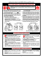
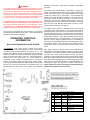
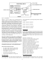
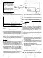
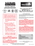
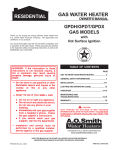
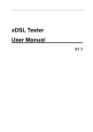
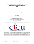
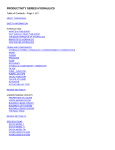
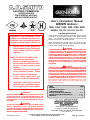
GAS-FIRED COMMERCIAL
COPPER BOILERS
FOR HYDRONIC HEATING
AND HOT WATER SUPPLY
User's Information Manual
GB/GW
MODELS:
1000, 1300, 1500, 1850, 2100, 2500
SERIES: 300, 301, 302, 303, 304, 305
LIGHTING INSTRUCTIONS
WARNING: If the information in this
manual is not followed exactly, a fire or
explosion may result causing property
damage, personal injury or loss of life.
•
Do not store or use gasoline or
other flammable vapors and liquids
in the vicinity of this or any other
appliance.
WHAT TO DO IF YOU SMELL GAS:
• Extinguish any open flame.
• Do not try to light any appliance.
• Do not touch any electrical switch;
do not use any phone in your
building.
• Immediately call your gas supplier
from a neighbor's phone. Follow
the gas supplier's instructions.
• If you cannot reach your gas
supplier, call the fire department.
•
Installation and service must be
performed by a qualified installer,
service agency or the gas supplier.
WARNING
SHOULD OVERHEATING OCCUR OR THE GAS SUPPLY FAIL
TO SHUT OFF, DO NOT TURN OFF OR DISCONNECT THE
ELECTRICAL SUPPLY TO THE PUMP. INSTEAD, SHUT OFF
THE GAS SUPPLY AT A LOCATION EXTERNAL TO THE
APPLIANCE.
These models have an automatic hot surface ignition system
mounted on the combustion chamber panel inside the front
jacket. This hot surface igniter ignites the main burner gas
whenever the system control calls for heat.
Before proceeding with operation of the unit, make sure the
boiler and system are filled with water and all air is expelled
from the boiler, radiator tank(s) and piping.
WARNING
THE MAIN MANUAL GAS SHUT-OFF VALVE MUST HAVE BEEN
CLOSED FOR AT LEAST FIVE (5) MINUTES BEFORE LIGHTING.
THIS WAITING PERIOD IS AN IMPORTANT SAFETY STEP. ITS
PURPOSE IS TO PERMIT GAS THAT MIGHT HAVE ACCUMULATED
IN THE COMBUSTION CHAMBER TO CLEAR. IF YOU DETECT
GAS AT THE END OF THE PERIOD DO NOT PROCEED WITH
LIGHTING. RECOGNIZE THAT GAS ODOR, EVEN IF IT SEEMS
WEAK, MAY INDICATE PRESENCE OF ACCUMULATED GAS
SOMEPLACE IN THE AREA WITH A RISK OF FIRE OR
EXPLOSION.
WARNING
THERE IS A RISK IN USING FUEL BURNING APPLIANCES SUCH
AS GAS WATER BOILERS IN ROOMS, GARAGES OR OTHER
AREAS WHERE GASOLINE AND OTHER FLAMMABLE LIQUIDS
ARE USED OR STORED, OR ENGINE-DRIVEN EQUIPMENT OR
VEHICLES ARE STORED, OPERATED OR REPAIRED.
FLAMMABLE VAPORS ARE HEAVY AND TRAVEL ALONG THE
FLOOR AND MAY BE IGNITED BY THE BOILER'S MAIN BURNER
FLAMES CAUSING FIRE OR EXPLOSION. Some local codes
permit operation of gas appliances if installed 18 inches or more
above the floor. This may reduce the risk if location in such an
area cannot be avoided.
INDEX
PAGE
GENERAL ........................................................................ 1
LIGHTING INSTRUCTIONS ....................................... 2 - 3
OPERATING SEQUENCE,
IGNITION CONTROLS INFORMATION ....................... 4 - 9
TROUBLESHOOTING & MAINTENANCE ............... 10 - 12
WARRANTY .................................................................. 15
WARNING
DO NOT USE THIS BOILER IF ANY PART HAS BEEN UNDER
WATER. IMMEDIATELY CALL A QUALIFIED SERVICE
TECHNICIAN TO INSPECT THE BOILER AND TO REPLACE ANY
PART OF THE CONTROL SYSTEM AND ANY GAS CONTROL
WHICH HAS BEEN UNDER WATER.
PRINTED IN U.S.A. 0802
A DIVISION OF A.O. SMITH CORPORATION
EL PASO, TX MC BEE, SC RENTON, WA
STRATFORD-ONTARIO, VELDHOVEN-THE NETHERLANDS
www.hotwater.com
PLEASE KEEP THESE INSTRUCTIONS ADJACENT TO BOILER AND
NOTIFY OWNER TO KEEP FOR
1 FUTURE REFERENCE
PART NO. 211817-000
Lighting Instructions for the G(B/W) 1000 through 2500 models
FOR YOUR SAFETY READ BEFORE OPERATING
WARNING: IF YOU DO NOT FOLLOW THESE INSTRUCTIONS EXACTLY, A FIRE OR
EXPLOSION MAY RESULT CAUSING PROPERTY DAMAGE, PERSONAL INJURY OR
LOSS OF LIFE.
A. THIS APPLIANCE DOES NOT HAVE A PILOT. IT IS
EQUIPPED WITH AN IGNITION DEVICE WHICH
AUTOMATICALLY LIGHTS THE BURNER. DO NOT TRY TO
LIGHT THE BURNER BY HAND.
B. BEFORE OPERATING: SMELL ALL AROUND THE APPLIANCE AREA FOR GAS. BE SURE TO SMELL NEXT TO THE
FLOOR BECAUSE SOME GAS IS HEAVIER THAN AIR AND
WILL SETTLE ON THE FLOOR.
WHAT TO DO IF YOU SMELL GAS:
• DO NOT TRY TO LIGHT ANY APPLIANCE.
• DO NOT TOUCH ANY ELECTRIC SWITCH; DO NOT
USE ANY PHONE IN YOUR BUILDING.
• IMMEDIATELY CALL YOUR GAS SUPPLIER FROM A
NEIGHBOR’S PHONE. FOLLOW THE GAS SUPPLIER’S
INSTRUCTIONS.
• IF YOU CANNOT REACH YOUR GAS SUPPLIER, CALL
THE FIRE DEPARTMENT.
C. USE ONLY YOUR HAND TO PUSH IN OR TURN THE GAS
CONTROL KNOB. NEVER USE TOOLS. IF THE KNOB WILL
NOT PUSH IN OR TURN BY HAND, DON’T TRY TO REPAIR
IT. CALL A QUALIFIED SERVICE TECHNICIAN. FORCE OR
ATTEMPTED REPAIR MAY RESULT IN A FIRE OR
EXPLOSION.
D. DO NOT USE THIS APPLIANCE IF ANY PART HAS BEEN
UNDER WATER. IMMEDIATELY CALL A QUALIFIED
SERVICE TECHNICIAN TO INSPECT THE APPLIANCE AND
TO REPLACE ANY PART OF THE CONTROL SYSTEM AND
ANY GAS CONTROL WHICH HAS BEEN UNDER WATER.
E. DO NOT OPERATE APPLIANCE UNLESS UNIT IS FILLED
WITH WATER AND WATER LINES ARE FULLY OPEN.
Note: Knob cannot be turned to "OFF" unless
knob is pushed in slightly. Do NOT force.
OPERATING INSTRUCTIONS
1.
2.
3.
4.
5.
6.
7.
STOP! READ THE SAFETY INFORMATION THE
NEXT STEP ABOVE ON THIS LABEL.
SET THE SYSTEM CONTROLLER TO THE LOWEST
SETTING.
TURN OFF ALL ELECTRIC POWER TO APPLIANCE.
THIS APPLIANCE IS EQUIPPED WITH AN IGNITION
DEVICE WHICH AUTOMATICALLY LIGHTS THE
BURNER. DO NOT TRY TO LIGHT THE BURNER BY
HAND.
REMOVE CONTROL ACCESS PANEL.
REFER TO DIAGRAMS ABOVE. TURN TOP KNOB OF
TO “OFF” POSITION,
GAS CONTROL CLOCKWISE
(FIGURE A).
WAIT FIVE (5) MINUTES TO CLEAR OUT ANY GAS. THEN
SMELL FOR GAS, INCLUDING NEAR THE FLOOR.
8.
9.
10.
11.
12.
IF YOU SMELL GAS,
STOP ! FOLLOW “B” IN THE SAFETY INFORMATION ABOVE ON THIS LABEL. IF YOU DON’T
SMELL GAS, GO TO THE NEXT STEP.
TURN TOP KNOB OF GAS CONTROL COUNTER
CLOCKWISE
TO “ON” POSITION, (FIG. B).
REPLACE CONTROL ACCESS PANEL.
TURN POWER SWITCH TO “ON” POSITION.
SET THE SYSTEM CONTROLLER TO DESIRED
SETTING.
IF THE APPLIANCE WILL NOT OPERATE, FOLLOW THE
INSTRUCTIONS “TO TURN OFF GAS TO THE
APPLIANCE” AND CALL YOUR SERVICE TECHNICIAN
OR GAS SUPPLIER.
TO TURN OFF GAS TO APPLIANCE
1. SET THE SYSTEM CONTROLLER TO THE LOWEST
SETTING.
2. TURN POWER SWITCH ON APPLIANCE TO “OFF”
POSITION.
3. REMOVE ACCESS PANEL TO EXPOSE GAS CONTROL.
4. REFER TO DIAGRAMS ABOVE. TURN TOP KNOB OF
GAS CONTROL CLOCKWISE (TO “OFF” POSITION,
(FIGURE A).
5. REPLACE CONTROL ACCESS PANEL.
2
Lighting Instructions for the G(B/W) 1000 through 2500 models
FOR YOUR SAFETY READ BEFORE OPERATING
WARNING: IF YOU DO NOT FOLLOW THESE INSTRUCTIONS EXACTLY, A
FIRE OR EXPLOSION MAY RESULT CAUSING PROPERTY DAMAGE,
PERSONAL INJURY OR LOSS OF LIFE.
A. THIS APPLIANCE DOES NOT HAVE A PILOT. IT IS
EQUIPPED WITH AN IGNITION DEVICE WHICH
AUTOMATICALLY LIGHTS THE BURNER. DO NOT TRY TO
LIGHT THE BURNER BY HAND.
• IF YOU CANNOT REACH YOUR GAS SUPPLIER, CALL THE
FIRE DEPARTMENT.
C. USE ONLY YOUR HAND TO TURN THE MAIN MANUAL GAS
VALVE HANDLE. NEVER USE TOOLS. IF THE HANDLE WILL
NOT TURN BY HAND, DON’T TRY TO REPAIR IT. CALL A
QUALIFIED SERVICE TECHNICIAN. FORCE OR ATTEMPTED
REPAIR MAY RESULT IN A FIRE OR EXPLOSION.
B. BEFORE OPERATING: SMELL ALL AROUND THE
APPLIANCE AREA FOR GAS. BE SURE TO SMELL NEXT
TO THE FLOOR BECAUSE SOME GAS IS HEAVIER THAN
AIR AND WILL SETTLE ON THE FLOOR.
D. DO NOT USE THIS APPLIANCE IF ANY PART HAS BEEN
UNDER WATER. IMMEDIATELY CALL A QUALIFIED
SERVICE TECHNICIAN TO INSPECT THE APPLIANCE AND
TO REPLACE ANY PART OF THE CONTROL SYSTEM AND
ANY GAS CONTROL WHICH HAS BEEN UNDER WATER.
WHAT TO DO IF YOU SMELL GAS:
• DO NOT TRY TO LIGHT ANY APPLIANCE.
• DO NOT TOUCH ANY ELECTRIC SWITCH.
• DO NOT USE ANY PHONE IN YOUR BUILDING.
• IMMEDIATELY CALL YOUR GAS SUPPLIER FROM A
NEIGHBOR’S PHONE. FOLLOW THE GAS SUPPLIER’S
INSTRUCTIONS.
E. DO NOT OPERATE APPLIANCE UNLESS UNIT IS FILLED
WITH WATER AND WATER LINES ARE FULLY OPEN.
OPERATING INSTRUCTIONS
1.
2.
3.
4.
5.
6.
STOP! READ THE SAFETY INFORMATION ABOVE
ON THIS LABEL.
SET THE SYSTEM CONTROLLER TO THE LOWEST
SETTING.
TURN POWER SWITCH ON APPLIANCE TO “OFF”
POSITION.
TURN MAIN MANUAL GAS VALVE TO “OFF” POSITION,
(FIGURE “B”). THE VALVE IS “OFF” WHEN THE HANDLE IS
PERPENDICULAR TO THE GAS FLOW DIRECTION.
THIS APPLIANCE IS EQUIPPED WITH AN IGNITION
DEVICE WHICH AUTOMATICALLY LIGHTS THE BURNER,
DO NOT TRY TO LIGHT THE BURNER BY HAND.
WAIT FIVE (5) MINUTES TO CLEAR OUT ANY GAS. THEN
7.
8.
9.
10.
SMELL FOR GAS, INCLUDING NEAR THE FLOOR. IF YOU
SMELL GAS,
STOP! FOLLOW “B” IN THE SAFETY INFORMATION ABOVE ON THIS LABEL. IF YOU DON’T SMELL
GAS, GO TO THE NEXT STEP.
TURN MAIN MANUAL GAS VALVE TO “ON” POSITION,
(FIGURE “A”), THE VALVE IS “ON” WHEN THE HANDLE
IS PARALLEL TO THE GAS FLOW DIRECTION.
TURN POWER SWITCH TO “ON” POSITION.
SET THE SYSTEM CONTROLLER TO DESIRED SETTING.
IF THE APPLIANCE WILL NOT OPERATE, FOLLOW THE
INSTRUCTIONS “TO TURN OFF GAS TO THE APPLIANCE” AND CALL YOUR SERVICE TECHNICIAN OR GAS
SUPPLIER.
TO TURN OFF GAS TO APPLIANCE
3. TURN MAIN MANUAL GAS VALVE TO “OFF” POSITION,
(FIGURE “B”). THE VALVEIS “OFF” WHEN THE HANDLE
IS PERPENDICULAR TO THE GAS FLOW DIRECTION.
1. SET THE SYSTEM CONTROLLER TO THE LOWEST
SETTING.
2. TURN POWER SWITCH ON APPLIANCE TO “OFF”
POSITION.
3
depending on the model. There will be one Ignition Control Board
per stage.
WARNING
THE UNIT SHOULD NOT BE INSTALLED DIRECTLY ON A
CARPETED FLOOR. A FIRE HAZARD MAY RESULT. Instead, the
boiler must be installed on the A. O. Smith Combustible Floor Kit
Base or concrete blocks extending beyond the full width and depth
of the boiler by at least 3 inches (76.2 mm). If the boiler is installed
in a carpeted alcove, the entire floor must be covered with concrete
blocks, or use the A. O. Smith Combustible Floor Kit Base.
The Central Control Board (CCB) is responsible for staging the
Ignition Control Boards (ICB) and monitoring safety limit devices,
control of circulation pump, power vent (if installed), alarm output
and IRI gas valves (only on IRI models). The thermostat also
resides on the CCB with inputs available for inlet, outlet and tank
temperature probes as well as an input for a remote 24 VAC
thermostat. The CCB has a display interface which connects to
the Display Board to show system status and failures. The CCB
also has a set of DIP switches which allows the user to control
several system parameters; see Figure 1.
FLAMMABLE ITEMS, PRESSURIZED CONTAINERS OR ANY
OTHER POTENTIAL FIRE HAZARDOUS ARTICLES MUST NEVER
BE PLACED ON OR ADJACENT TO THE BOILER. OPEN
CONTAINERS OF FLAMMABLE MATERIAL SHOULD NOT BE
STORED OR USED IN THE SAME ROOM WITH THE BOILER.
The Interface Board, Figure 3, distributes power to the various
components of the control system. It also contains test points for
the 24VAC devices in the safety circuit, as well as fuses for each of
the stage ICBs and the pump. Along the bottom of the interface
board, several green LEDs show the state of various safety control
devices during operation. If the LED is illuminated, the contact to
the particular device is in its desired state. To test the 24VAC
signal of a device, attach the positive terminal of a multimeter to
the test port, run the negative terminal to a suitable ground location
and read the voltage. Note: Test ports are the metal terminals
located below each of the green LEDs along the bottom of the
board.
Light the unit in accordance with the instructions on the lighting
and operating label attached to the boiler. These instructions are
repeated on the previous two pages.
OPERATING CONTROLS
INFORMATION
MULTI-STAGE FIRING AND CONTROL SYSTEM
ALL MODELS - The control system consists of four basic
components: 1) Central Control Board 2) Ignition Control Board
3) Display Board 4) Interface Board; see Figures 14-17. The
Central Control Board, Ignition Control Boards and the Interface
Board are located in the control box and can be accessed through
panels on the left side and top of the unit. The Display Board is
attached to the front jacket panel. The control system is a
multi-stage control capable of managing three or four ignition
stages. Three stage models include the 1000, 1300 and 1500.
Four stage models include the 1850, 2100 and 2500. Every system
will have one Central Control Board, one Interface Board, one
Display Board and either three or four Ignition Control Boards
Each stage requires an Ignition Control Board (ICB) which is
responsible for controlling a combustion blower, hot surface igniter
and gas valve. Each ICB is capable of monitoring gas valve power,
gas valve relay, flame sense and igniter current. The ICB is
designed to communicate with the Central Control Board (CCB).
Each ICB consists of identical hardware and software. Each stage
ICB is made unique through the use of circuit board jumpers which
allow the user to control such variables as stage identification and
blower/igniter usage. See Figure 2 for jumper configurations.
These jumpers are preset at the factory and should only be
adjusted by a qualified service technician.
DIP SWITCH CONFIGURATION TABLE
SW1
OFF
ON
SELECTION:
A
3 STAGE
4 STAGE
EITHER 3 OR 4 STAGE SYSTEM
B
3 TRIALS
1 TRIAL
EITHER 3 OR 1
C NO IRI GAS VALVE IRI GAS VALVE WHETHER SYSTEM IS IRI OR
STANDARD
D
INLET
TANK
INLET OR TANK AS CONTROLLING
PROBE
E
NO EXTERNAL
EXTERNAL
WHETHER EXTERNAL THERMOSTAT
THERMOSTAT
THERMOSTAT IS USED
F
OUTLET 210°F OUTLET 240°F OUTLET MAXIMUM TEMPERATURE
G
190°F
220°F
MAXIMUM INLET SET-POINT
TEMPERATURE
H
DEGREES °F
DEGREES °C EITHER °F OR °C FOR DISPLAYED
TEMPERATURE
Figure 1. Dip Switch Configurations for Central Control Board
4
RED LED
INDICATES
FUSE FAILURE
INTERCOMMUNICATIONS CABLE
GREEN
POLARITY
LED
J25 JUMPER MUST BE IN PLACE ON THE FINAL ICB OF THE
CONTROL STRING. THIS WILL CORRESPOND WITH STAGE 3
ICB ON GB/GW 1000 - 1500 AND STAGE 4 ICB ON GB/GW
1850 - 2500.
Figure 2. Jumper Configurations for Ignition Control Board.
ICB AND
PUMP FUSES
MAIN POWER
CONNECTIONS
LOW GAS AND
OPTIONAL ITEM
CONNECTIONS*
GREEN LED
INDICATORS
PUMP RELAY
CONNECTIONS
TEST PORTS
Figure 3. Interface Board Components.
Ignition Control Boards and a 5 amp fuse on the Central Control
Board. If the fuse opens, a red LED located near the fuse will light;
see Figures 1 and 2. If the red LED is illuminated, replace the
fuse.
The Display Board allows the end user to monitor water
temperature, setpoints, differentials, options, fault indications and
error codes. Display Board pushbuttons labeled "ADJUST",
"SELECT" AND "ENTER/RESET" enable the user to adjust setpoint,
differentials, post-circulate time, reset the cycle count and reset
the control system during lockout. Changes made to
programmable features are stored in nonvolatile memory.
Repeated failure of the fuse is an indication of possible damage
to the ignition control.
Note: Four extra 3 amp fuses and one 5 amp fuse are supplied
with the boiler.
Line Polarity Indicator
A green LED is mounted on each Ignition Control Board to indicate
line voltage polarity is properly connected; see Figure 2. When
120VAC input power is properly connected to the Ignition Control
Board, the green LED will illuminate. If an error is made when
connecting 120VAC input power, this LED will not light.
Recommended Replacement fuses:
3 Amp: Littlefuse automotive fuse PN 257003
5 Amp: Bussman Automotive fuse PN ATC5
Fuse Protection
The Display Board provides a user-friendly interface to the Central
Control Board. With the Display Board, the user can control
appliance functions and view the overall operating status of the
DIA-SCAN II DISPLAY BOARD OPERATING PROCEDURES
The 24VAC circuitry is protected with a 3 amp auto fuse on the
5
Figure 4. Display Board
Set-Point differential for a given stage is being viewed or adjusted;
see Figure 4.
appliance. If an error condition occurs, the Display Board will
indicate the nature of the fault by illuminating a red LED. The
display will further define the fault by illuminating a red LED
corresponding to the stage on which the fault has occurred. Each
stage has both a red and green LED associated with it to indicate
either a fault or normal operation. If the fault continues until the unit
"locks out", the display will show a three digit code in addition to
the red LEDs. See Table 1 for error code chart. Under normal
operating conditions, the four digit LED display on the Display
Board will continuously show the water temperature sensed at the
inlet temperature probe. If dip switch "D" on the Central Control
Board is placed in the "ON" position, it will show the temperature at
the tank probe; see Figure 1. The push buttons on the Display
Board allow the user to program and view several system
parameters described in the following text. The Display Board is
connected to the Central Control Board through a 6 conductor
cable assembly with modular plug terminations. In addition, an 8
conductor modular jack on the Display Board allows for
connecting a remote Display Board.
STAGE 1: Stage One in Operation
STAGE 2: Stage Two in Operation
STAGE 3: Stage Three in Operation
STAGE 4: Stage Four in Operation
Red Fault Lights
The Red LEDs are illuminated to show faults and help in trouble
shooting. There are three faults (High Gas Fail, LWCO and Power
Vent Fail) listed as "Optional" which are only functional when the
particular "Optional" equipment is connected to the boiler. The red
stage LEDs indicate the stage on which a given fault has occurred;
see Figure 4.
When power is applied to the Control System, the Display Board
will initially run through a self-diagnostic test, and then display the
inlet temperature. To display a specific setting or temperature,
press the SELECT push-button until the appropriate LED is
illuminated; see Figure 4. After 5 seconds, the Display Board will
automatically revert to displaying the Inlet temperature. Pressing
the ENTER/RESET push-button will hold the display in the indicated
mode until the SELECT push-button is pressed.
Blocked Flue: Blockage in Flue
Probe Fail: One of the controlling Probes has failed
Insufficient Air: Not enough Air to Close Switch
Circulate Fail: Flow Switch Not Closed
Gas Valve Fail: Relay for Gas Valve in Incorrect State
High Limit: High Limit has been Exceeded
Flame Fail: No Flame Sensed on Ignition
Igniter Fail: Igniter did not reach Minimum Amperage
Low Gas Fail: Gas Pressure too low to Close Switch
High Gas Fail: Gas Pressure at Manifold too High
LWCO: Low water Cutoff activated. Not enough water in system.
Power Vent Fail: Not Enough Air to Close Switch
Stage One: Failure on Stage One
Stage Two: Failure on Stage Two
Stage Three: Failure on Stage Three
Stage Four: Failure on Stage Four
With the display board, the user can make adjustments to many of
the appliance’s control features. This includes the following:
Options/Features Setting Procedures
•
Set Appliance Stage Temperature Setpoint Value
•
Set Appliance Stage Switching Differential Value
•
Select Appliance Post-Circulate Time
•
Check Appliance Cycle Count
•
View Last Error Encountered by Control
•
Control the water temperature in a storage tank
Yellow Parameter Set Lights
Green Status Lights
The five yellow parameter set lights allow the user to view system
set points and options. In conjunction with the four green stage
Green LEDs indicate when a given stage has sensed flame and is
in the heating state. They also are used to indicate when the
6
Encase field-supplied wires
between tank probe and junction
box with 1/2" field supplied
conduit. "Pigtails" of fieldsupplied wires should be spliced
to "pigtails" of tank probe and
connected to 24VAC junction box.
This conduit and wiring should be
separate from any other conduit/
wiring to guard against EMI
(electromagnetic interference).
Figure 5. Tank Probe Installation
1.
Press the SELECT push-button on the Display Board until
both the Set-Pt LED and Outlet Water Temperature LED are
illuminated; see Figure 4.
Temperature.
2.
The LED display will show the current set-point temperature.
Temperature shown is Outlet Water
Note: Under no circumstances should the Outlet/ECO be set to
exceed 210°F (99°C) in applications where the boiler is
heating potable water. Failure to observe this will void
the warranty.
LEDs, the user can monitor and change settings on the various
stages; see Figure 4.
Inlet*:
Temperature shown is Inlet Water
Outlet:
Temperature.
Set-Point:
Indicates controlling probe setpoint
is being displayed.
Set-Point Differential:
Shows differentials of each stage.
Standby:
Indicates Set-Point is Satisfied.
Inlet Probe
The Inlet probe is located on the right side of the Inlet/Outlet header.
It has one set of blue wires embedded in it which senses the
temperature at the probe. The Inlet Probe is considered a
controlling probe and can be used to control the staging of the unit.
The inlet probe set-point is fully adjustable between the factory set
minimum value of 80°F (25°C) and a user controlled maximum
value which will depend on the unit's application. In GW
applications, the maximum Inlet Set-Point is 190°F (88°C) and in
GB application it is 220°F (104°C). The Inlet probe Set-Point can
be adjusted between these two maximum values using Dip Switch
"G" on the Central Control Board which is located inside the control
box; see Figure 1.
Boiler in Idle State.
*Defaults to tank probe temperature when Dip Switch "D"
on Central Control Board is Switched to the "ON" position; see
Figure 1.
TEMPERATURE PROBES
All units come with two temperature probes connected to the Inlet/
Outlet header. Additionally, an optional tank probe (thermistor type)
or 24VAC thermostat/aquastat can be connected to the unit. The
probes can be categorized as two types: controlling probes and
safety limit probes. Controlling probes can control the staging of
the boiler. Safety limit probes are used as resettable high limit
switches. The two controlling probes are the inlet probe and the
tank probe. The function and setting of the probes is further
described in the following sections.
To change or view the current programmed temperature set-point
for the Inlet Temperature probe value:
1.
Outlet Probe
2.
3.
The Outlet Temperature/ECO probe is located on the left side of
the header and has two sets of wires embedded in it. The black
wires sense the temperature at the probe. Their output is shown
on the display screen when the "OUTLET" LED is illuminated. The
red wires control the ECO (Emergency Cutoff) which shuts down
the unit if the water temperature exceeds 250°F (121°C) and
requires a manual reset of the boiler. The outlet probe functions
as a automatically resettable high limit and is not considered a
controlling probe on the boiler, which means it cannot be set to
control the staging of the unit. Depending on the application of the
boiler, the probe is set to one of two settings. In GW applications,
the maximum Outlet Set Point is 210°F (99°C) and in GB
applications it is 240°F (115°C). The Outlet probe Set Point can be
adjusted between these two values using Dip Switch "F" on the
Central Control Board inside the control box; see Figure 1.
4.
5.
6.
7.
Press the SELECT push-button on the Display Board until
both the Set-Pt LED and Inlet Water Temperature LED are
illuminated; see Figure 4.
The LED display will show the current set-point temperature.
Press and hold the ADJUST push-button. The displayed
temperature will either increase or decrease. To alternate
between increasing or decreasing the temperature, release
then press and hold the ADJUST push-button.
When the desired set-point temperature is reached, release
the ADJUST push-button.
Press the ENTER/RESET push-button once, this enters the
selected set-point temperature into controller memory.
The appliance will now control the temperature to the desired
set-point value.
For setting the stage differentials, see the section labeled
Procedure for Setting Stage Differential.
NOTE:
To view the current programmed temperature set-point for the Outlet
Temperature probe:
7
The boiler must complete a full cycle in order for the
new setting to take effect. If the unit is turned off prior
to a complete cycle the setting will be lost and the
previous setting will remain in effect.
Procedure for Setting Stage Differentials
24VAC System Controller (Optional)
Once the system control and set-point temperature has been
entered, the switching differentials for the staging of the unit must
be established. To facilitate proper operation and maximize
appliance performance, each stage has a programmable
switching differential or “hysteresis” about the set point. This means
a call for heat for a particular stage will become active when the
water temperature measured at the controlling temperature
sensing probe drops to the set-point value minus the switching
differential value. It is necessary to set three set-point differential
values for three stage units and four for four stage. The burner will
remain on until the water temperature measured at controlling
probe reaches the stage set-point value. The switching
differential value is fully programmable from 0°F to 20°F (0°C to
11°C) using the push-button(s) located on the Display Board.
A 24VAC thermostat/aquastat can be implemented as a system
controller on Genesis units. The connection for such devices is
located in the 24VAC junction box at the rear of the unit. A 24VAC
thermostat/aquastat can only be used as an "On/Off" switch for the
unit. The actual controlling of the staging will be through either the
inlet or tank probe. To use a 24VAC system controller, dip switch
"E" on the CCB must be switched to the "on" position; see Figure 1.
Tank Probe (Optional)
In additon to the Inlet and Outlet/ECO Probes, units can be optionally
equipped with a tank probe. The connection for the tank probe is
located in the 24VAC junction box at the rear of the unit. The tank
Probe can be configured to control the staging of the unit. See
"Tank Probe Installation Procedure" section below for additional
information.
To change or view the current programmed switching differential:
TANK PROBE INSTALLATION PROCEDURE (GW Models)
1.
A tank probe is supplied with each hot water supply boiler (GW). To
connect the tank probe to the boiler, remove the cover from the
24VAC junction box at the rear of the unit. Connect the probe wires
across terminals 1 & 2. (The wires leading to the terminals will be
yellow.) Check the field connection diagram located below the
junction box to assure proper wiring; see Figure 5.
2.
3.
Once the tank probe has been connected to the boiler, it must be
designated as the controlling probe for the system. This is
accomplished by changing two Dip Switch settings on the Central
Control Board. First, Dip Switch "D" must be set to the "ON" position
to designate the tank probe as the controlling probe. Second, Dip
Switch "G" must be set to the "OFF" position to limit the maximum
tank probe temperature for GW applications. It is also advisabe to
make sure Dip Switch "F" is set to the "OFF" position which sets
the Outlet temperature Set-Point to 210°F (99°C). If the tank probe
is not designated as the controlling probe, the staging of the unit
will be controlled by the Inlet Probe and will not use the desired
tank temperature as its base. Once the tank probe is designated
as the controlling probe, the inlet water temperature on the display
will default to the tank temperature. Refer to Connection Diagram
in the Installation Manual (P/N 211816-000) for wiring connection.
4.
5.
6.
7.
Example:
Application: Hydronic Heating
Desired System Temperature: 185°F (85°C)
Stage Differentials: 5°F (3°C) per Stage
Procedure for Setting Tank Probe Temperature
Note: The user must choose which probe is to control the staging
of the unit. The controlling probe will be either the inlet or tank
probe. (If the tank probe is used to regulate loop temperature in
hydronic applications (GB), make sure it is located on the return
side of the closed loop.) Use Dip Switch "D" on the Central Control
Board to make this selection; see Figure 1.
The user can easily change or view the water temperature
set-point at any time by using the following procedure:
1.
2.
3.
4.
5.
6.
7.
Press the SELECT push-button on the Display Board until
both the Set-Pt Diff. and green Stage One LED are
illuminated; see Figure 4.
The LED display will show the current differential for stage
one.
Press and hold the ADJUST push-button. The displayed value
will either increase or decrease. To alternate between
increasing or decreasing the differential, release then press
and hold the ADJUST push-button.
When the desired Set-Pt differential is reached, release the
ADJUST push-button.
Press the ENTER/RESET push-button once, this enters the
selected set-point differential into controller memory. To view
the Set-Pt minus the Set-Pt differential, press and hold the
"ENTER" push-button. This will be the "turn-on" temperature
for Stage One and the "turn-off" temperature for Stage Two.
Repeat steps 2 through 5 for the rest of the stages.
The appliance will now control temperature utilizing the
desired differentials.
Press the SELECT push-button on the Display Board until
both the Set-Pt LED and Inlet Water Temperature LED are
illuminated; see Figure 4.
The LED display will show the current set-point temperature.
Press and hold the ADJUST push-button. The displayed
temperature will either increase or decrease. To alternate
between increasing or decreasing the temperature, release
then press and hold the ADJUST push-button.
When the desired set-point temperature is reached, release
the ADJUST push-button.
Press the ENTER/RESET push-button once, this enters the
selected set-point temperature into controller memory.
The appliance will now control the temperature to the desired
set-point value.
For setting the stage differentials, see the section labeled
Procedure for Setting Stage Differential.
Set the stage differentials using the procedure described in the
"Procedure for Setting Stage Differential" section of the document.
Setting the control as described in the above example (5°F
differentials for each stage) will give the following stage set-points.
Stage One
Off Temperature: 185°F (85°C) / On Temperature: 180°F (82°C)
Stage Two
Off Temperature: 180°F (82°C) / On Temperature: 175°F (79°C)
Stage Three
Off Temperature: 175°F (79°C) / On Temperature: 170°F (77°C)
Stage Four
Off Temperature: 170°F (77°C) / On Temperature: 165°F (74°C)
8
Procedure for Setting Pump Delay
The Controller is factory set with a 45 second post circulate function.
With the Display Board, the user has the capability to choose
between a 45, 90, or 180 second post circulate time period, or turn
the pump on continuously. This provides flexibility in selecting the
post circulate time to meet specific installation requirements, and
improves the efficiency of the circulating pump operation.
6.
Appliance Operating Sequence
1.
When power is applied to the control system, the Display Board
will initially run through a self-diagnostic routine, and then go
into its operating mode, displaying the temperature sensed at
the controlling probe. This can be either the inlet or tank probe.
2. If the ignition control determines the actual water temperature
at the controlling temperature probe is below the programmed
temperature setpoint minus the switching differential, and the
thermostat circuit or tank probe circuit is closed, a call for heat
is activated.
3. The control then performs selected system diagnostic checks.
This includes confirming the proper state of the ECO/High
Limit device, flow switch*, and pressure switches.
*Note: Correct water flow is vital to the operation of the
boiler. See the Installation Manual (P/N 211816-000) for
requirements on flow, head loss and heat exchanger
pressure drop.
4. If all checks are successfully passed, the circulating pump
circuit is energized. Once the flow switch has closed, all
combustion blowers will energize for a 30 second pre-purge
cycle.
5. When the pre-purge cycle is complete, all blowers except stage
1 will drop out. Power is then applied to the stage 1 igniter
element for the igniter warm-up period.
6. The control will verify igniter current. After the verification, the
gas valve will open, allowing gas to enter the burner.
7. After an additional 1 second, the control will monitor the flame
sensing probe to confirm a flame is present. If a flame is not
verified within 4 seconds, the gas valve is immediately closed.
The control will initiate a 15 second inter-purge period and
return to step 2, unless dip switch "B" is in the "ON" position, in
which case it will proceed to "lockout".
8. If a flame is confirmed, stage two will be activated. The blower
associated with stage two (if applicable) will start. Once the
blower has been proven, igniter two will begin its warm-up
period. (This is true on all units except the 1000 which has
only one igniter.) After the igniter current has been proven,
stage two will begin a trial for ignition.
9. Stage three will activate after flame is proven on stage two. If
applicable, the blower associated with stage three will begin.
Once the blower has been proven, a trial for ignition will begin
on stage three. If flame is not proven, there will be a 15
second interpurge on stages with an associated blower. The
boiler will then begin additional trials for ignition. On stages
without an associated blower, a five second delay will occur
before the gas valves are opened for additional trials for
ignition.
Note: Stages on which no blower or igniter is present will
bypass the blower and igniter proving periods. The gas valves
will open five seconds after a call for heat is initiated on the
stage.
10. Once all of the stages have been satisfied, the pump will run
for the programmed post-circulate cycle (factory default 45
seconds). See "Procedure for Setting Pump Delay" section
on previous page.
11. The control now enters the idle state. This is indicated on the
display by the "Standby" LED. The control will continuing to
monitor temperature and the state of other system devices. If
the water temperature at the designated system controller
To change or view the current programmed post-circulating time:
1.
2.
3.
4.
5.
6.
Press the SELECT push-button on the Display Board until the
LED display reads "OP" (Options); see Figure 4.
To enter into the options mode, press the ENTER/RESET pushbutton.
The display will illustrate "Crcu". Enter this mode by pressing
the ENTER/RESET push-button.
The display will now illustrate the current post circulate time.
Press the ADJUST push-button to select the desired post
circulate time (45, 90, 180, "con").
When you have selected the desired post circulate time mode,
press the ENTER/RESET push-button once, this enters the
time into controller memory.
The display will automatically return to illustrating the controlling
probe temperature after five (5) seconds.
Last Error Code
In this mode, the Display Board will illustrate the last error which
caused the unit to "lock-out". When this mode is entered the three
digit failure code that was in memory last will be displayed. See
Table 2 for error codes. For example, if the appliance "locked-out"
due to insufficient air on stage one, the display will show 041. To
enter into this mode, perform the following steps:
1.
2.
3.
4.
5.
Press the SELECT push-button on the Display Board until the
LED display reads "OP" (Options); see Figure 4.
To enter into the options mode, press the ENTER/RESET
push-button.
The display will illustrate "Crcu". Press the SELECT
push-button until the display illustrates "Ler". Enter this mode
by pressing the ENTER/RESET push-button.
The display will illustrate the last error detected by the control.
The display will automatically resort to illustrating the
controlling probe temperature after five (5) seconds.
Display Stage Cycle Count
The Central Control Board counts the number of cycles each stage
of the appliance has operated by counting how many times the
gas valve(s) are energized. To check the cycle count for each
stage, perform the following procedure:
1.
2.
3.
4.
5.
Press the ENTER/RESET push-button to successfully reset the
cycle count. If the ENTER push-button is not pressed, the reset
function will not be saved and the original cycle count will
continue to increment on each gas valve operation.
The display will automatically return to illustrating the
controlling probe temperature after five (5) seconds.
Press the SELECT push-button on the Display Board until the
LED display reads "OP" (Options); see Figure 4.
To enter into the options mode, press the ENTER/RESET
push-button.
The display will illustrate "Crcu". Press the SELECT
push-button until the display illustrates "CC". Enter this mode
by pressing the ENTER/RESET push-button.
The display will now illustrate the current number of cycles
stage one has fired. Notice that the green Stage One LED is
illuminated. Pressing the ENTER/RESET button again will
cause the green Stage Two LED to illuminate and the cycle
count for stage two will be displayed on the screen. Cycle
counts for the other stages can be viewed in a similar fashion.
To reset the cycle count to zero, press the ADJUST push-button.
9
USE ANTI-SCALD VALVE(S) in the hot water system to reduce the
risks of scalding at points of use such as lavatories, sinks and
bathing facilities.
drops below the setpoint value minus the switching differential,
and the thermostat circuit or tank probe circuit closes, the
control will return to step 2 and repeat the entire operating
cycle. During this idle state, if the control detects an improper
operating state for external devices such as the ECO switch,
air pressure switch, gas pressure switch, etc., the
appropriate red LED(s) on the Display Board will illuminate
indicating the nature of the fault.
TROUBLESHOOTING AND MAINTENANCE
The control system has several features to aid in troubleshooting
problems which may occur during operation. If a fault occurs, the
Display Board contains sixteen (16) red fault LED indicators to
help pinpoint the source of failures. In addition, the display will
inform the user on which stage the failure occurred by illuminating
a red Stage LED. In cases where the problem persists to lockout,
the appropriate red LEDs will remain illuminated and a three digit
error code will flash on the display screen. A summary of error
codes is given in Table 2. The error codes are broken into two
categories: hard lockouts and soft lockout.
DANGER
HOT WATER TEMPERATURES REQUIRED FOR AUTOMATIC
DISHWASHER AND LAUNDRY USE CAN CAUSE SCALD
BURNS RESULTING IN SERIOUS PERSONAL INJURY AND/OR
DEATH. THE TEMPERATURE AT WHICH INJURY OCCURS
VARIES WITH THE PERSON'S AGE AND TIME OF EXPOSURE.
THE SLOWER RESPONSE TIME OF CHILDREN, AGED OR
DISABLED PERSONS INCREASES THE HAZARDS TO THEM.
NEVER ALLOW SMALL CHILDREN TO USE A HOT WATER TAP,
OR TO DRAW THEIR OWN BATH WATER. NEVER LEAVE A CHILD
OR DISABLED PERSON UNATTENDED IN A BATHTUB OR
SHOWER.
Hard Lockouts:
Hard lockouts require a manual reset accomplished by pressing
the Enter/Reset push-button on the display board. Cycling the
power "OFF" and "ON" will not reset the control.
Soft Lockouts:
Soft Lockouts also require a manual reset accomplished by
pressing the Enter/Reset push-button on the display board.
However, under a soft lockout condition, the control will re-initiate
an ignition process after one (1) hour provided the call-for-heat is
still present and will continue every hour until the unit is either
reset or ignites.
A description of the red fault LEDs and their corresponding
functions are as follows. Also refer to Figure 4.
THE WATER HEATER SHOULD BE LOCATED IN AN AREA WHERE
THE GENERAL PUBLIC DOES NOT HAVE ACCESS TO SET
TEMPERATURES.
LED
Controller Function
Blocked Flue
Indicates a blockage or interference at
the appliance flue.
Indicates failure at one of the
temperature probes. Unit will "lockout"
only if controlling probe fails.
Indicates air pressure was too low to
create a sufficient differential to close
the differential pressure switch.
Indicates water flow was too low to
close the flow switch.
Monitors Gas Valve relay output. LED
is ON when the output relay supplying
power to the gas valve(s) is open.
Monitors ECO in the Outlet Tempera
ture probe. LED is ON when the ECO
is open.
Monitors the Flame Sense Rod. LED
is ON when a signal from the flame rod
is not sufficient to indicate flame.
Indicates igniter current was too low to
meet minimum value which allows trial
for ignition to continue.
Inlet gas pressure is not sufficient to
close gas pressure switch.
Manifold gas pressure has exceeded
designed maximum value.
Indicates water level in system is too
low for safe operation.
Air pressure at Power Vent Switch is
not sufficient for safe operation.
Temp. Probe Fail
IT IS RECOMMENDED IN DOMESTIC HOTWATER APPLICATIONS
THAT LOWER WATER TEMPERATURES BE USED TO AVOID THE
RISK OF SCALDING. IT IS FURTHER RECOMMENDED, IN ALL
CASES, THAT THE WATER TEMPERATURE BE SET FOR THE
LOWEST TEMPERATURE WHICH SATISFIES THE USER'S HOT
WATER NEEDS. THIS WILL ALSO PROVIDE THE MOST ENERGY
EFFICIENT OPERATION OF THE BOILER AND MINIMIZE SCALE
FORMATION IN THE HEAT EXCHANGER, THUS PROLONGING
THE LIFE OF THE BOILER.
Insufficient Air
Circulate Fail
Gas Valve Fail
High Limit
SETTING THE WATER HEATER TEMPERATURE AT 120°F (49°C)
WILL REDUCE THE RISK OF SCALDS. SOME STATES/
PROVINCES REQUIRE SETTINGS AT SPECIFIC LOWER
TEMPERATURES. TABLE 1 BELOW SHOWS THE APPROXIMATE
TIME-TO-BURN RELATIONSHIP FOR NORMAL ADULT SKIN.
Flame Fail
Igniter Fail
TABLE 1. Risk of Scalds
Temperature
Setting
Time to Produce 2nd & 3rd
Degree Burns on Adult Skin
Over 170°F (77°C)
160°F (71°C)
150°F (66°C)
140°F (60°C)
130°F (54°C)
120°F (49°C) or less
Nearly instantaneous
About 1/2 second
About 1-1/2 seconds
Less than 5 seconds
About 30 seconds
More than 5 minutes
Low Gas Fail
High Gas Fail*
LWCO Fail*
Power Vent Fail*
*Optional Equipment - LEDs will illuminate only if equipment is
connected to boiler. Upon lockout, manually push the ENTER/
RESET button on the display panel to restart the boiler.
10
MAIN BURNERS
After placing the boiler in operation, check the ignition system safety
shut-off devices for proper operation. To accomplish this with the
main burners operating, close the valve on the manifold. Within
four seconds the main burners should extinguish. If this does not
occur immediately, discontinue gas supply by closing main manual
shut-off and call a qualified serviceman to correct the situation. If
the burners extinguish, then light boiler in accordance with lighting
and operating instructions.
Check main burners every three months for proper flame
characteristics.
The main burner should display the following characteristics:
•
•
•
•
Provide complete combustion of gas.
Cause rapid ignition and carry over of flame across entire
burner.
Give reasonably quiet operation during initial ignition,
operation and extinction.
Cause no excessive lifting of flame from burner ports;
see Figure 6.
For installations above 4500 feet (1350 m), refer to HIGH ALTITUDE
INSTALLATIONS in the Installation Manual (P/N 211816-000).
DO NOT STORE COMBUSTIBLE MATERIALS, GASOLINE, OR
OTHER FLAMMABLE VAPORS, LIQUIDS IN THE AREA OF THE
APPLIANCE. NONCOMPLIANCE MAY RESULT IN FIRE OR
EXPLOSION. DO NOT OBSTRUCT THE FLOW OF COMBUSTION
OR VENTILATION AIR TO THE APPLIANCE.
CHEMICAL VAPOR CORROSION
Boiler corrosion and component failure can be caused by airborne
chemical vapors. Spray can propellants, cleaning solvents,
refrigerants, calcium or sodium chloride (water softener salts),
waxes, chlorine and process chemicals are typical compounds
that are potentially corrosive. These materials are corrosive at very
low concentration levels with little or no odor to reveal their presence.
Products of this sort should not be stored near the boiler. Air which
is brought in contact with the boiler should not contain any of these
chemicals. The boiler should be provided with air from outdoors
when installed in environments having corrosive atmospheres.
Figure 6. Burner Flame Characteristics
If the preceding burner characteristics are not evident, check for
accumulation of lint or other foreign material that restricts or blocks
the air openings to the burner or boiler.
CIRCULATION PUMP
NOTE: Cleaning of main burners.
Refer to the pump manufacturer's schedule of maintenance for
frequency and method of lubricating the pump and motor. Inspect
the pump once a month for leaky mechanical seals and/or O-rings
and loose or damaged components. Contact a qualified service
agent to replace or repair parts as required.
1.
2.
3.
4.
Shut off all gas and electricity to unit. Allow boiler to cool.
Remove main burners from unit.
Check that burner venturi and ports are free of foreign matter.
Clean burners with bristle brush and/or vacuum cleaner.
DO NOT distort burner ports.
5. Reinstall burners in unit. Ensure that all the screws on the
burner flange are tightened securely so that the gasket will
provide a good seal. Also, ensure that each orifice is centered
with the venturi opening of every burner.
BLOCKED VENT SHUT-OFF SYSTEM
The boiler is equipped with a blocked vent shut-off system which
will close the gas valve and shut off the main burner gas when
there is excessive pressure pressuring the vent system due to a
partially or completely blocked vent. The display on the front panel
will indicate this failure condition.
Note: Make sure the washer of each pre-jet orifice is inserted
at least 1/4 into the burner tube and that it is not touching the
sides of the burner tube. This is critical for proper operation;
see Figure 7.
DO NOT ATTEMPT TO OPERATE THE BOILER if this situation
occurs. Shut the boiler off before performing all the steps shown
in "TO TURN OFF GAS TO APPLIANCE" section of the Lighting and
Operating Instructions.
6. Check for good flow of combustion and ventilating air to the
unit.
Contact a qualified service agent to inspect the unit and vent system
and correct the problem.
VENT SYSTEM
The flue products are corrosive in nature and if the boiler is vented
horizontally the flue gases are at a higher pressure than the
surrounding air pressure. Inspection of the boiler and vent system
is necessary to insure that flue gas leakage to the surrounding
area does not occur.
Inspect the external surfaces of the vent system every 6 months for
corrosion and leakage. Inspect the vent terminations for corrosion
and foreign matter (including ice) which may be blocking the
exhausting flue products. Call a qualified service agent to replace
Figure 7. Burner/Orifice Insertion
11
FAILURE DUE TO LIME OR SCALE BUILDUP VOIDS THE
WARRANTY.
or repair any corroded or leaking parts.
Qualified service agent must inspect internal surfaces of the vent
system and the boiler at least once a year.
COMBUSTION AIR BLOWER
The bearings in the motor are pre-lubricated and sealed at the
factory. The bearings should be oiled once every six months per
the manufacturer's recommended maintenance schedule. Use
SAE-29 non-detergent oil.
DELIMING
The amount of calcium carbonate (lime) released from water is in
direct proportion to water temperature and usage. The higher the
water temperature or water usage, the more lime deposits are
dropped out of the water. This is the lime scale which forms in
pipes, boilers and on cooking utensils.
RELIEF VALVE
The safety relief valve should be opened at least twice a year to
check its working condition. This will aid in assuring proper
pressure relief protection. Lift the lever at the top of the valve several
times until the valve seats properly and operates freely.
The usage of water softening equipment greatly reduces the
hardness of water. However, this equipment does not always
remove all of the hardness (lime). For this reason it is
recommended that a regular schedule for deliming be maintained.
DANGER
THE WATER PASSING OUT OF THE VALVE DURING CHECKING
OPERATION MAY BE EXTREMELY HOT. BEFORE OPERATING
RELIEF VALVE, MAKE SURE DRAIN LINE IS INSTALLED TO
DIRECT DISCHARGE TO A SAFE LOCATION SUCH AS AN OPEN
DRAIN, TO AVOID SCALDING OR WATER DAMAGE.
The time between cleaning will vary from two to six months
depending upon water conditions and usage. A change of
approximately 5°F (3°C) in the normal temperature rise through
the boiler is usually an indication that scale should be removed.
For long life, copper or brass is recommended for all valves, pipe
and fittings.
WARNING
SHOULD OVERHEATING OCCUR OR THE GAS SUPPLY FAIL TO
SHUT OFF, TURN OFF THE MANUAL GAS CONTROL VALVE TO
THE APPLIANCE.
CAUTION
LIME ACCUMULATION CAN REDUCE THE LIFE OF THE
EQUIPMENT, REDUCE EFFICIENCY AND WASTE FUEL. BOILER
12
Table 2. Error Code Chart
GENESIS II CONTROL - FAULT OPERATION
FAULT
COMMUNICATIONS FAULT (CCB TO ICB)
STAGE 1:
STAGE 2:
STAGE 3:
STAGE 4:
ERROR CODES
LOCKOUT
001
002
003
004
HARD
HARD
HARD
HARD
ECO/HIGH LIMIT:
NO GAS VALVE POWER SENSED
STAGE 1:
STAGE 2:
STAGE 3:
STAGE 4:
LWCO
CIRCULATE FAULT (FLOW SWITCH)
010
HARD
011
012
013
014
020
030
HARD
HARD
HARD
HARD
HARD
SOFT
INSUFFICIENT AIR (AIR PRESSURE SWITCH)
STAGE 1:
STAGE 2:
STAGE 3:
STAGE 4:
BLOCKED FLUE
POWER VENT
041
042
043
044
060
070
SOFT
SOFT
SOFT
SOFT
SOFT
SOFT
IGNITER FAILURE
STAGE 1:
STAGE 2:
STAGE 3:
STAGE 4:
LOW GAS FAILURE
081
082
083
084
090
HARD
HARD
HARD
HARD
HARD
HIGH GAS FAILURE
STAGE 1:
STAGE 2:
STAGE 3:
STAGE 4:
101
102
103
104
HARD
HARD
HARD
HARD
GAS VALVE RELAY FAILURE
STAGE 1:
STAGE 2:
STAGE 3:
STAGE 4:
111
112
113
114
HARD
HARD
HARD
HARD
FLAME FAILURE
STAGE 1:
STAGE 2:
STAGE 3:
STAGE 4:
121
122
123
124
HARD
HARD
HARD
HARD
PROBE FAULTS
OUTLET PROBE
INLET PROBE
REMOTE PROBE
IRI GAS VALVE FAILURE
CPU FAULT
131
132
133
140
210
HARD
HARD
HARD
HARD
HARD
For additional information please refer to the Owner’s Manual supplied with the boiler or contact:
A.O. Smith Technical Services 7 a.m. to 7 p.m. Central Time at: 1-800-527-1953
Our Internet Site is another source of information 24 hours a day.
http://www.hotwater.com
13
NOTES:
14
NEW BOILER LIMITED WARRANTY
A. O. Smith Corporation, the warrantor, extends the following LIMITED WARRANTY to the owner of this hydronic boiler:
1.
If within TEN years after initial installation of the boiler, the heat exchanger shall prove upon examination by the warrantor to be defective in material
or workmanship, the warrantor, at his option, will exchange or repair such part or portion. This term is reduced to FIVE years if this boiler is used
for volume hot water supply purposes other than hydronic space heating.
a. This warranty is extended to the owner for all other parts or portion during the FIRST year following initial installation of this boiler.
b. The warranty on the repair or replacement of the part or portion will be limited to the unexpired term of the original warranty.
2.
CONDITIONS AND EXCEPTIONS
This warranty shall apply only when the boiler is installed in accordance with local plumbing and building codes, ordinances and regulations, the
printed instructions provided with it and good industry practices. In addition, an appropriately sized safety relief valve certified to the ASME Boiler
and Pressure Vessel Code must have been installed and fresh water used for filling and makeup purposes;
a. This warranty shall apply only when the boiler is used:
(1) at temperatures not exceeding the maximum setting of its operative and/or high limit control;
(2) at water pressure not exceeding the working pressure shown on the boiler;
(3) when filled with boiler water, free to circulate at all times and with the heat exchanger free of damaging scale deposits;
(4) in a noncorrosive and non-contaminated atmosphere;
(5) in the United States, its territories or possessions, and Canada;
(6) at a water velocity flow rate, not exceeding or below the Boiler's designed flow rates;
b. Any accident to the boiler, any misuse, abuse (including freezing) or alteration of it, any operation of it in a modified form will void this warranty.
3.
SERVICE AND REPAIR EXPENSE
Under this limited warranty the warrantor will provide only a replacement part. The owner is responsible for all other costs. Such costs may include
but are not limited to:
a. Labor charges for service removal, repair or reinstallation of the component part;
b. Shipping, delivery, handling, and administrative charges for forwarding the replacement part from the nearest distributor and returning the
claimed defective part to such distributor.
c. All cost necessary or incidental for any material and/or permits required for installation of the replacement.
4.
LIMITATIONS ON IMPLIED WARRANTIES
Implied warranties, including any warranty of merchantability imposed on the sale of this boiler under state law are limited to one (1) year duration
for the boiler or any of its parts. Some states or provinces do not allow limitations on how long an implied warranty lasts, so the above limitation may
not apply to you.
5.
CLAIM PROCEDURE
Any claim under the warranty should be initiated with the dealer who sold the boiler, or with any other dealer handling the warrantor’s products.
If this is not practical, the owner should contact:
U.S. Customers
A. O. Smith Water Products Company
5621 West 115th Street
Alsip, IL 60803
Telephone: 800-323-2636
a.
b.
6.
Canadian Customers
A. O. Smith Enterprises Ltd.
P. O. Box, 310 - 768 Erie Street
Stratford, Ontario N5A 6T3
Telephone: 800-265-8520
The warrantor will only honor replacement with identical or similar parts thereof which are manufactured or distributed by the warrantor.
Dealer replacements are made subject to in-warranty validation by warrantor.
DISCLAIMERS
NO OTHER EXPRESS WARRANTY HAS BEEN OR WILL BE MADE ON BEHALF OF THE WARRANTOR WITH RESPECT TO THE MERCHANTABILITY OF
THE BOILER OR THE INSTALLATION, OPERATION, REPAIR OR REPLACEMENT OF THE BOILER. THE WARRANTOR SHALL NOT BE RESPONSIBLE
FOR WATER DAMAGE, LOSS OF USE OF THE UNIT, INCONVENIENCE, LOSS OR DAMAGE TO PERSONAL PROPERTY OR OTHER CONSEQUENTIAL
DAMAGE. THE WARRANTOR SHALL NOT BE LIABLE BY VIRTUE OF THIS WARRANTY OR OTHERWISE FOR DAMAGE TO ANY PERSONS OR
PROPERTY, WHETHER DIRECT OR INDIRECT, AND WHETHER ARISING IN CONTRACT OR TORT.
a. Some states or provinces do not allow the exclusion or limitation of the incidental or consequential damage, so the above limitations or
exclusions may not apply to you.
b. This warranty gives you specific legal rights, and you may also have other rights which vary from state to state or province to province.
Fill in the following for your own reference. Keep it. Registration is not a condition of warranty. The model and serial number are found on the boiler’s
rating plate.
Owner______________________________________________________________________________________________________________________
Installation Address________________________________________________________________________________________________________
City and State or Province ___________________________________________________________________________________________________
Date Installed
___________
Model No.
___________________________
Serial No. ____________________________
Dealer’s Name______________________________________________________________________________________________________________
Dealer’s Address__________________________________________________________________Phone No. ________________________________
FILL IN WARRANTY AND KEEP FOR FUTURE REFERENCE
15
REPLACEMENT PARTS
16