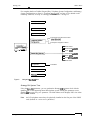
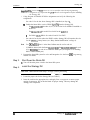
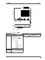
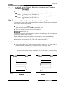
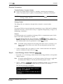
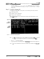
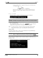
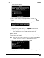
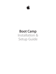
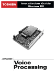
1
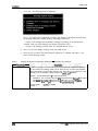
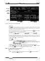
Before You Start...
Get ready to install Toshiba’s Stratagy DK, one of the most efficient voice processing systems
available! To make this installation go smoothly, before
anything else, please read and
complete both sides of this checklist:
1
Do you know
how to handle
Stratagy DK?
care and it will last a
long time.. .
Do you have
everything you
need?
Need more details?
They’re inside the
ins
tion guide.
Is Strata DK
ready?
See the Strata DK
tion
Maintenance and
Programming
Manuals for details
on a specific Strata
DK product.
Whenever handling Stratagy DK, always wear the anti-static
wrist strap (included); keep the strap by the unit. Always
the unit by its edges. Remember that electrostatic charge from
your body, even your own body oils can damage Stratagy DK.
Never drop or jar Stratagy DK! The unit’s hard drive is
extremely sensitive to dropping or excessive force during
installation.
Temperature changes greater than
cause condensation on
Stratagy
hard drive. Wait 24 hours before installation if
there is such a temperature variation.
What comes shipped: Stratagy DK comes complete with
loaded operating software, documentation package and the antistatic wrist strap. Make sure nothing is missing or damaged.
Local Administration? You’ll need a portable/desktop PC with
hard drive space, 3.5” 1.44 floppy drive, and
DOS
null-modem serial cable or
580KB free RAM. You’ll need a
Toshiba’s SG-ADMCBL cable to connect your PC to
Stratagy DK.
a Remote (modem) Administration? Use Stratagy Admin
software (up to 9600 baud) with Toshiba’s SG-FMOD modem or
modem connected to
a Hayes-compatible, 14.4 baud,
Stratagy
serial Port 2; don’t forget the
serial cable.
a You can also use Stratagy
internal (soft)
modem and administrate through its phone connection.
Make sure
DK is compatible with your Strata DK: It
with all
and
systems. It also
works with
with Release 4 software.
Always program Strata slot assignments before installing the
Stratagy DK. Use these slot assignments:
DK424: use a universal slot, starting with slot 12 or 13 if an
is in slot 11; never use slots
68, 71, 77, or 78.
use any universal slot, starting with slot 12 or slot 13 if
is in slot 11 (R3 or higher); never use slots 31 or 51.
an
use any expansion cabinet slot (except slot 18
in the
that takes an eight-port card.
DK96: use any slot after slot 01.
Be sure to set code 31 in Program 03 for the slot where
Stratagy DK will be installed.
All Strata
if receiving Calling Party Control (CPC) or Loop
Open Disconnect from the CO, use Program 15 to enable.
Always remember to shut down Stratagy software before
powering down Strata DK.
Strata DK needs to recognize Stratagy
DTMF signaling.
Make sure an RRCS is installed in the
a
in the
or CRCU in the
DK96.
Run Program 03 and assign these code(s) where the DTMF
receiver is installed:
installed on the RCTU): code
or
94 for slot 00.
code 92 for slot 00.
(CRCU): code 92 or 93 for slot 00.
Is Strata
DTMF tone
detection
enabled?
Make sure a PDKU card is installed that is currently (or can be)
programmed for a DSS Console.
When installing Stratagy DK in an
numbered cabinet make sure the PDKU is in a lowernumbered slot in the same cabinet. When installing in an
even-numbered cabinet, the PDKU must be in a lowernumbered slot in the
odd-numbered cabinet.
set slot 11 in’the Base Cabinet to code 64.
the PDKU must reside in slot 01.
Set code 64 using Program 03 for the PDKU slot.
See the installation guide to program Stratagy DK for this option.
5
Do you want to
activate the
Busy Lamp
feature?
Are you going to
have
a
Want to synch.
Stratagy DK
system time
with Strata DK?
All set?
Just a few more
things...
you
is only available on a
processor or
higher.
Make sure a
card is available.
Set code 43 in Program 03 for
or code 49
for
The
card must be located close to the
Stratagy DK. Install a serial cable between the two.
You’ll need an LCD telephone physically installed on Strata DK;
make sure it’s on the first port of the PDKU card (defined in Step
5 above).
Don’t forget to wear the anti-static wrist strap during handling.
Be sure Stratagy DK has a jumper installed on J4.
If you are using an internal modem in the portable/desktop
computer, remember that Stratagy Admin only works with COM
1 and 2, not COM 3 or 4.
Do not write over the Stratagy Admin subdirectory on your
remote PC when installing the Stratagy Admin
version
you received. Always retain previous versions of Admin.
a Make sure your Strata I&M/Programming Manuals and Stratagy
l&M Manuals are handy. Be sure to read the entire installation
guide before installing.
Remember to back up your database after installation.
and completed this checklist, installation will be a breeze!
started!
4011014
Contents
Stratagy DK
.....1
What’s New? . . . . . . . . .
Internal Modem . . . . . . . . . . . . . . . . . . . . . . . . . . . . . . . . . . . . . . . . . . . . . . . . . . . . . . . . . . . . . . . . . . . . . . . . . . . . . . . . . . . . . . . . . . . . . . . . . . . . . . . . . . . . . . . . . . . . . . . . 1
1
Enhanced Stratagy Admin Software . . . . . . . . . . . . . . . . . . . . . . . . . . . . . . . . . . . . . . . . . . . . . . . . . . . . . . . . . . . . . . . . . . . . . . . . . . . . . . . . . . . .
..................................................................... 2
Parameters . . . . . . . . . . . . . . . . . . . . . . . . . . . . . . . . . . . . . . . . . . . . . . . . . . . . . . .
2
Main Menu . . . . . . . . . . . . . . . . . . . . . . . . . . . . . . . . . . . . . . . . . . . . . . . . . . . . . . . . . . . . . . . . . . . . . . . . . . . . . . . . . . . . . . . . . . . . . . . . . . . . . . . . . . . . . . . . . . . . . . . .
4
Users Menu Options Screen . . . . . . . . . . . . . . . . . . . . . . . . . . . . . . . . . . . . . . . . . . . . . . . . . . . . . . . . . . . . . . . . .
4
Tokens .............................................................................................................................................
4
Features ............................................................................................................................................
5
Installation ..............................................................................................................................................
Step 1: Read Through this Installation Guide First.. .................................................................... 5
Step 2: Program the Strata DK ....................................................................................................
Step 3: Shut Down the Strata DK ................................................................................................ 6
Step 4: Install the Stratagy DK ..................................................................................................... 6
Step 5: Verify Stratagy DK is Functioning Properly ................... . ..............................................
Step 6: Verify that Voice Playback, Basic Auto Attendant and Ports
are Functioning Correctly
Step 7: Connect Portable/Desktop Computer to Stratagy DK ................................................... 10
Local Connection
Remote Connection ................................................................................................................. 11
.................................................................... 11
Step 8: Load Stratagy Admin Software
Step 9: Configure Stratagy Admin Software ............................................................................
14
.......................................................................................................
Step 10: Access Stratagy
Local Access ..........................................................................................................................
Remote Access ........................................................................................................................ 15
Step 11: Configure Stratagy DK .................................................................................................
Toshiba Plug and Play ............................................................................................................. 17
Telephone System Configuration ............................................................................................ 18
Stratagy System Configuration ..............................................................................................
Step 12: Program the Mailboxes .................................................................................................
Step 13: Application Programming.. ............................................................................................ 23
Step 14: Stratagy DK Maintenance .............................................................................................. 25
25
Tools ........................................................................................................................................
Trace Diagnostics ......................... . .......................................................................................... 31
Upgrading Stratagy DK Voice Ports ....................................................................................... 31
Step 15: Shut Down the Stratagy DK .........................................................................................
Stratagy
Installation Guide April 1997
i
Figures
Figure 1
Figure 2
Figure 3
Figure 4
Figure 5
Figure 6
7
Figure 8
Stratagy DK Hardware Components .............................................................. .l
Navigating the Tools Menu ....................................... ..................................... 3
Stratagy
PDKU
Lam Field
Slot Assignment Examples ............................................................................... 8
Stratagy DK ...................................................................................................... 9
RS-232 DB9 to DB9 Cabling ......................................................................... 10
RS-232 DB25 to DB25 Cabling ..................................................................... 10
Main Menu with Sample Data ....................................................................... 16
Options Screen with
Data .................................................................
Tables
Table 1
Table 2
Table 3
Table 4
Table 5
ii
Stratagy Admin Compatibility ..........................................................................
Stratagy DK Slot Assignment ...........................................................................
Stratagy DK Status/Port
..........................................................................
Admin PC Configuration Fields .....................................................................
Stratagy DK System Configuration Parameters Definitions and Settings .
2
7
9
13
0
Stratagy DK Installation Guide April 1997
Stratagy DK
The Stratagy DK voice processing circuit card (see Figure 1 for a photograph) s u p p o r t s up to 8
ports, provides up to 24 hours of storage and is installed in the card slot of a Strata DK Base or
Expansion
The supported systems and recommended
software versions are:
Strata
Strata
Strata
all releases
all releases
Release 4
The Stratagy DK requires Stratagy Admin
software, installed on a separate
compatible portable/desktop computer, for
local or remote administration and
maintenance. With the release of the
Stratagy DK, a new enhanced version of
is available.
Stratagy Adrnin
This enhanced version provides new
utilities, explained in detail later in this
Guide, for configuring and maintaining the
Stratagy DK.
Voice mail integration is provided by
Strata DK in-band
integration.
Strata DK424 and DK280 can also provide
integration using the Simplified Message
Desk Interface (SMDI) output of the PIOU,
PIOUS, RSSU, RSIU, or RSIS SMDI port.
Figure 1
Stratagy DK Hardware
Components
What’s New?
Internal Modem
The Stratagy DK has an internal (soft) modem that operates at up to 2400 baud and can be
used for remote maintenance.
Enhanced Stratagy Admin Software
With the release of the Stratagy DK, a new version of Stratagy Admin
is available.
This new version provides enhanced abilities for configuring and maintaining the
Stratagy
DK Installation Guide April 1997
1
What’s New?
Stratagy DK. Some versions of the Stratagy
Stratagy system software (see Table 1).
Table 1
software are not compatible with the
Stratagy Admin Compatibility
Compatible Stratagy Admin
Software Version
Stratagy DK System
Software Version
Stratagy 4 Lite
software does not support some of the utilities available in
Admin
new menu selection called Tools (see Page 2). If ONLY performing mailbox programming on the
Stratagy 4 Lite (version V4
Admin
can be used. Total compatibility will be available with Stratagy 4 Lite Release 3 software.
Parameters
Because of the unique nature of the interaction process between the Stratagy DK and
Strata DK, four new parameters have been added for use exclusively with the Stratagy DK
(see Table 5 for the definitions and settings for these parameters).
designates the PDKU slot. Stratagy
slot for
status.
tells the Stratagy DK to retrieve BLF busy station information for the assigned
DSS Port field located on the Users Menu Options screen (see Step 12 “Program the
Mailboxes” on Page 22 for information on programming the field).
synchronizes Stratagy
system clock with the system clock of the
supporting Strata DK telephone system.
trace-cap: defines the size of the trace file in kilobytes.
Main Menu
Starting with
Admin, the Main Menu has been changed to include a new menu
selection, called Tools, and the time display (in the upper right corner of the menu) has an
additional feature exclusive to the Stratagy DK. The time display now indicates whether the
Stratagy DK is synchronized with the Strata DK KSU (KSU time) or is running on its own
system clock (standard, daylight savings).
Tools
Tools includes the following selections (see Figure 2):
Backup Utility
Upgrade Utility
Toshiba Plug and Play
Retrieve Trace File
Functions supported by the
2
Restore Utility
Telephone System Configuration
Stratagy System Configuration’
Filecopy’
4
Stratagy
‘Installation Guide April 1997
Strategy DK
What’s New?
For complete details on Toshiba Plug and Play, Telephone System Configuration, and Stratagy
System Configuration, see Step 11 “Configure
DK” on Page 16. For details on the
remaining selections, see Step 14 “Stratagy DK Maintenance” on Page 25.
Backup Utility
Restore Utility
Upgrade Utility
Edit Telephone Systems Dial Codes
Edit System Integration Patterns
Strata DK424
Strata DK424
Strata
Strata DK280
Strata
.
Strata
Strata DK16
Stratagy System
Configuration
Parameters
Retrieve Trace File
Figure 2
Navigating
Menu
Stratagy DK System Time
Using the
parameter, you can synchronize Stratagy
system clock with the
system clock of the supporting Strata DK telephone system. Setting-this parameter to true,
daylight-saving-time parameter. The Main Menu screen displays KSU time when
disables
this feature is enabled.
Note
An LCD telephone must always be physically installed on the first port of the PDKU
card (defined in console-slot-id parameter).
Stratagy DK Installation Guide April 1997
Stratagy
What’s New?
- -
- _ - - - - - -
Users Menu
Options Screen
You’ll notice some changes in the User Menu
are:
Options screen. The changes (see Figure 8)
A new field called DSS Port has been added. This new field replaces the Alternate Rate
feature, which is not available with the Stratagy DK.
The Message Volume feature, although displayed on the screen, is not supported by the
Stratagy DK.
DSS Port
The
Port field corresponds to the “physical” port number of a Strata DK station. This field
enables the Stratagy DK to monitor the Busy Lamp field of a DSS console port to determine if
the station is busy before attempting to transfer.
Tokens
AS with all Stratagy systems the Stratagy DK retains all of the robust application programming
that is provided by tokens. Some new tokens are available exclusively for the Stratagy DK.
They are:
KM Enables a portable/desktop computer’s modem to communicate with the
Stratagy DK internal modem (2400 baud) by sending the call to User ID 993.
KT( )
Directs calls to a designated User ID when:
DSS function is active
= true)
DSS port is assigned in the “answering” mailbox
Night Transfer on the DSS console is ON.
Features
Busy Station Identification
The Busy Station Identification feature enables the Stratagy DK to determine if a station is
“busy” without performing a “hook-flash” and transfer. Stratagy DK “reads” the data of a DSS
console and knows instantly if the station is busy or in Do Not Disturb (DND).
A station in DND mode signals a “busy” condition to a DSS console. DND and busy are
processed the same way by
Stratagy DK (i.e., the Busy chain is executed).
new console-slot-id and
parameters,
To use this feature you must configure
program the new
Port field (see Step 12 “Program the Mailboxes” on Page
and
install/program a PDKU as the DSS console (see
Lamp Feature” on Page 7).
Important! Once the
Lamp feature has been programmed using the two
Stratagy DK must be re-started two times. The
parameters and the
re-start
the
The second re-start “loads” the
DSS
into active memory.
Night Transfer Alternate Routing
Using the new KT( ) token, a new feature called Night Transfer Alternate Routing is now
available. The feature monitors the DSS Night Transfer key in order to activate the
token for alternate routing applications.
4
Stratagy
installation Guide April 1997
--
Limiting
File Size
Trace is a diagnostic tool that is designed to assist you in troubleshooting Stratagy’s activity.
To log the trace data, you can use a text file called TRACE.OUT. The size of the trace file can
be configured using the new trace-cap parameter, which defines the size of the trace file in
kilobytes. When the size of the trace file reaches the setting limit, the existing file is
overwritten, beginning with the oldest record.
Installation
You will be handling the Stratagy DK when it is most fragile
unpackaged and exposed. The
Stratagy DK, if handled properly, will give long, reliable service. To insure that the unit is not
damaged during installation or maintenance, follow these precautions.
CAUTION!
Damage may not always be immediately evident (e.g., no physical damage on the outside
of the unit) and system failure may result weeks or months later.
Step I :
.
Handle the Stratagy DK with care. Mechanical shock from dropping, shaking,
excessive force when seating the board into the slot, rocking a connector on or other
activities can severely damage the disk assembly or the disk’s printed circuit board.
.
Wear the anti-static wrist
included in the package. It can also be re-used and left
with the Strata DK cabinet. An electrostatic charge from your body can damage the
hard drive or other circuitry permanently.
.
Hold the
DK by the edges or the strap and never touch the board’s surface.
Pressure on the printed circuit board or contaminants from your hands (e.g., skin oil,
food particles, hand lotion) can cause component failure.
Read Through this Installation Guide First
Before starting the installation, read through these instructions thoroughly. Important
information is included in this Guide that is crucial to a successful installation.
Step 2:
Program the Strata DK
Note
The following instructions are based on the Stratagy DK being installed in a preexisting Strata DK. If the Strata DK is a new installation, see First Programming in
of the Strata
Programming Manual for more information.
Chapter 1
To the Strata DK processor, the Stratagy DK functions as an analog card
Although
there are some special program settings required for the Stratagy DK (e.g.,
feature),
the Strata DK should be programmed just as it would for any external voice mail system that is
to be connected to it.
Stratagy
DK Installation Guide April 1997
5
Stratagy DK
Installation
Strata DK
1.
initialize some Strata programming
make all such assignments before installing
need to be reset to
assignments. It is important that
the Stratagy DK.
Using Program 03-Flexible PCB Slot Assignments set/verify the following slot
assignments:
.
Set code 31 for the slot where Stratagy DK is installed (see Step 4
Enable the Strata DK to receive DTMF
from the Stratagy DK:
. For
Set codes 92, 93, or 94 for slot 00 for the RRCS installed on
the RCTU.
l
l
Note
l
For
Set code 92 for slot 00 for the
For DK24,
DK96: Set codes 92 and 93 for CRCU.
Set code 64 for the slot where the PDKU resides. Stratagy DK will monitor this slot
for the
Lamp feature (see “Busy Station Identification” on Page 4).
For
slot 11 in the Base Cabinet must be set for code 64.
If SMDI is desired with the Strata
Set
for code
for code 49 to enable the SMDI port (see Program 76 if installing
43 or
RSIU or RSIS SMDI port).
2. Program the Strata DK system for voice mail integration. See the Strata
Manual for details.
Step 3:
Programming
Shut Down the Strata DK
Turn off the main power switch to the Strata DK system.
Step 4:
install the Stratagy DK
CAUTION! See cautions under Step 1 on Page 5 before proceeding.
- 1. Locate the proper slot for the Stratagy DK (see Table 2).
2. Insert the card into the appropriate slot, and apply firm, even pressure to ensure proper
mating of connectors. Do not hit the board for proper seating. This may damage the
Stratagy DK components.
Stratagy DK
April 1997
Stratagy DK
Table 2
Installation
Stratagy
Slot Assignment
DK424
Note
For the
the
feature, the Stratagy DK must reside in a higher-numbered slot than
card that the Stratagy DK will monitor (see Figure 3).
install the card in a universal slot starting with slot 12 (if a PDKU or PEKU
is in slot 11)
Important! Do not install the Stratagy DK in slots 27,
71, 77, or 78.
37, 37,
in slot
or
(if a
47, 48, 57, 57, 58, 67, 68,
To enable end-to-end signaling, ensure that an RRCS -4, -8 or -12 is installed on the RCTU, and verify
that the RCTU code in Program 03 is for RRCS operation.
DK280
The Stratagy DK does not function when installed in slots 31 or 51.
Note
For the
feature, the Stratagy DK must reside in a higher-numbered slot than the
card that the Stratagy DK will monitor (see Figure 3)
DK280 (R2) -install the card in any universal slot (except slots 31 and
Base Cabinet.
starting with slot 12 of the
DK280 (R3 or higher) install the card in any universal slot (except slots 31 and
slot 12 (if a PDKU or PEKU is in slot 11) or slot 13 (if a
is in slot 11)
starting with
(All releases) -To enable end-to-end signaling, an RRCS -4, -8 or -12 must be installed on
the RCTU. Verify that the RCTU code in Program 03 is for RRCS operation.
.
Install the Stratagy DK in any slot in the Expansion KSU where an eight-port card can be inserted. For
see Tables 2-7-2-l 3 in Chapter 2
Configuration the
for
all possible configurations.
Important! Do not install Stratagy DK in slot 78 of the
A
6e.
must be installed in the Base KSU to enable end-to-end signaling
Note
Putting a Stratagy DK into a Strata
eliminates eight telephone lines.
Install the card in any slot after slot 01. A CRCU must be installed to enable end-to-end signaling.
For the
Lamp feature to operate (see “Busy Station Identification” on Page 4 for detailed
information), the Stratagy DK must monitor the
data from a specific PDKU card. The
Strata DK telephone system restricts this capability to certain configurations:
Stratagy DK cannot be installed in the first slot of any cabinet (i.e., 11-71)
The Stratagy DK can only monitor a PDKU that resides in an odd-numbered cabinet.
Stratagy DK must always be in a higher-numbered slot than the PDKU card, even if the PDKU is
in another cabinet.
When Stratagy DK is installed in an odd-numbered cabinet, the system software searches for the
PDKU in all lower-numbered card slots in that cabinet (as defined by the console-slot-id parameter
on Page 21). When the Stratagy DK is installed in an even-numbered cabinet, the system software
searches for the PDKU in all lower-numbered card slots of the preceding odd-numbered cabinet. See
Figure 3 for examples.
Stratagy DK Installation Guide April 1997
Installation
Stratagy DK
- -
Stratagy DK in Even Number Cabinet
Stratagy DK in Odd Number Cabinet
Cabinet 1
Cabinet 2
Stratagy DK
Cabinet 3
PDKU
PDKU
Cabinet 4
Figure 3
Step 5:
Stratagy
PDKU
(console-slot-id configured as 0)
Stratagy DK
Lamp Field Slot
Examples
Verify Stratagy DK is Functioning Properly
Note
Each Stratagy DK has been pre-programmed at the factory for out-of-box (plug and
play) operation on the Strata DK280. This includes the integration and configuration
parameters, default station (extension number) User ID mailboxes, and company
greeting and instructions.
1. Turn on the main power switch to the Strata DK system and the Stratagy DK performs a
self test while booting-up.
2. Let it proceed without any action from you. During this process the status light is blinking
amber and should turn solid
when finished (see Figure 4 and Table 3). The process
should take approximately four to five minutes.
Stratagy DK Installation Guide April
Stratagy
Installation
Backplane Connector
Hard Drive
Side
View
Strap
I
Figure 4
Table 3
Stratagy DK
Stratagy DK Status/Port
Dark
Green
At boot-up:
Dark
No power
Blinking Amber
Power-on, self-test.
Red
Failed self-test. The port
indicate which test(s) failed:
Port LED
Green
Test Failed
1
DRAM
2
RTC
3
EEPROM
4
EPROM Checksum
5
Hard Disk
6
Integration Processor
7
. . .
DSP
While system is
System is operational.
Green
System is operational and hard drive
Green with
Blinking Amber is active.
Stratagy DK Installation Guide April 1997
Port
is on-hook and idle.
Port is off-hook and in use.
Stratagy DK
-
Step 6:
-
that Voice Playback, Basic Auto Attendant and Ports are
Functioning
Dial the extension number for each port, Stratagy should (for each port):
Answer and play the Toshiba Plug and Play company greeting (“Thank you for
calling..
greeting 1 in User ID mailbox 990.
Continue to play the Toshiba Plug and Play caller instructions greeting (“To reach the
greeting in User ID mailbox 991.
person..
Step 7:
Connect Portable/Desktop Computer to Stratagy DK
To program the Stratagy DK, a IBM-compatible portable/desktop computer must be connected
to the Stratagy and have the following:
3.5” 1.44 (high-density)
Hard drive with a minimum of
drive
of available disk space
DOS V6.2 or higher must be resident on the hard drive
RAM memory free
Communication between the portable/desktop computer and the Stratagy DK is accomplished
by one of two methods: local or remote.
Stratagy DK uses the serial Port 2 by default to communicate with the portable/desktop
computer (see Figure 4). This setting can be changed using the admingort parameter in the
System Configuration file (see Table 5 for detailed information).
Local Connection
Using a null-modem cable, connect the portable/desktop computer to the Stratagy DK. A
prefabricated cable (SG-ADMCBL), designed expressly for Stratagy Admin
communication with the Stratagy DK, is available from Toshiba.
Note
For those who wish to purchase individual cabling/connectors/adapters in lieu of
purchasing the Toshiba Stratagy Admin cable, we have provided the following wiring
diagrams.
female
Figure
10
female
2
3
5
3
2
7
a
a
7
FE-232
to
Cabling
female
2
3
4
female
2
3
a
5
Figure 6
DB25 to DB25 Cabling
Stratagy DK
April 1997
Stratagy
Installation
Remote Connection
Portable/Desktop Computer Modem
Prepare the portable/desktop computer by installing, connecting and configuring a
modem. The modem must be capable of communicating at a minimum of 2400 baud
CAUTION! Internal modems configured for COM ports 3 or
Stratagy Admin software.
not supported by
Stratagy Modem
The Stratagy DK can communicate through either an internal or external modem.
Internal
The Stratagy DK has an internal modem that communicates at up to 2400 baud. No additional
equipment is necessary. (See KM token in Step 13 “Application Programming” on Page 23 for
programming information.)
External
An external modem can be installed on the Stratagy DK for a communication speed of 9600
baud. If 9600 baud communication is desired:
1.
the Stratagy DK with a Hayes-compatible 14400
modem. Toshiba’s fax/
modem (SG-FMOD) has been tested for consistent operation and is recommended. Use of
other modem models cannot be guaranteed for trouble
operation.
Note
2.
Step 8:
The default setting configured for the Stratagy DK remote access is serial port 2 (see
Figure 4). Local and remote access utilize the same designated serial port on the
Stratagy DK.
Connect a telephone line to the modem. Use either a station connected to the telephone
system or a dedicated Central Office (CO)
Load Stratagy Admin Software
1. Insert disk 1 of 1 of the Stratagy Admin software into the floppy-disk drive of the portable/
desktop computer.
Note
If currently running Windows@, you will need to obtain a DOS prompt (C :
by shutting down Windows or by using the MS-DOS program or shell.
Do this
2. Type a : install c :
to begin the installation procedure. (It is recommended
that you not overwrite the current Admin directory but create a new directory.)
The following messages are displayed:
DK
installation
Guide April 1997
11
3. Press any key to continue and the Stratagy Admin program is installed on drive C: in
subdirectory ADMIN3.
Step 9:
Configure Stratagy Admin Software
Settings for the communication port in Stratagy Admin must match the corresponding
parameters set in the Stratagy System Configuration file on the Stratagy DK.
For example, if using COM 1 on the portable/desktop computer and serial Port 2 on the
must be identical to the
Stratagy DK, the Stratagy Admin Serial Port definitions for
serial port definitions (i.e., set
in the Stratagy System Configuration file on the
Stratagy DK.
Note
The menu screens detailed in this section are only available with Admin version
or later.
1. From the C :
DOS prompt, type
and p r e s s E n t e r .
The Stratagy Admin Main screen is displayed:
Note
Press
for help with any settings in the Admin Configuration screen.
2. Press 2 or highlight the Configure Admin option and press E n t e r .
The following screen appears:
Note
Press F2 in the Serial Port and Baud Rate fields to display a pop-up box with valid
entries.
3. See Table 4 for a description of each of the fields. To save your changes, you must press
E n t e r or the arrow down
key from the last field (i.e., Modem
String). The
returns to the Admin Main screen.
12
installation Guide April 1997
Stratagy DK
To exit without saving your changes, you may press Esc at any time. The Stratagy Admin
Main screen is displayed.
Table 4
Admin PC Configuration Fields
Field
Advertising
Description/Default
Advertising string that displays when the Main Menu screen blanks after a specified number of
minutes of inactivity (per
parameter in the
file).
string. The single quotes are required.
Possible values:
Default. ‘Stratagy
Log File
System log file name. This log file contains start-up information, any execution error information,
system actions, and shutdown information
Note
a good idea
periodically archive or delete
whenever you perform preventive maintenance.
Possible values: 8-character file name, plus
Default: ‘Remote.LOG’
Serial Port
file once or twice a
character extension. The single quotes are required
Port number
Possible values: l-4
Default: 2
Baud Rate
Baud rate of serial port.
Possible values:
Default: 9600
Modem lnit
String
1200, 2400, 9600
Sets modem initialization string. The modem initialization string can be changed to work with
specific brand modems. Refer to the user’s manual for your individual modem for the initialization
string.
Default: AT&F&Cl
where:
AT
The command that tells the modem to come to Attention.
Return to factory defaults.
instructs the modem to use the factory set parameters.
&Cl
Data Carrier Detect (DCD) signal.
Set to on, it indicates presence of a data carrier.
Ready selected.
LO
Speaker volume.
Off or low volume
Mode responses.
Enables result codes to be issued to the screen.
vo
Result code format.
Numeric format.
Extended result codes
Disables
of busy tones unless forced otherwise by country requirements.
only OK, connect, ring, no carrier, error and no answer result codes.
El
Stratagy
Command Character Echo.
Enables echoing of the commands to the screen
Installation Guide
Sends
Stratagy DK
Installation
Access Stratagy DK
Prior to accessing Stratagy, verify that Stratagy is operational by making a test call into the
system.
Note
Menu screens detailed in this section are available only in Admin version
later.
From the DOS prompt
or
type: admin and press E n t e r .
The following screen is displayed:.
Important! The portable/desktop computer must be
Stratagy Admin prior to performing
for
the correct serial port in
2.
2. Press 1 or highlight the Connect to Stratagy option and press E n t e r .
3. The
software prompts for the Stratagy
(the default is S t r a t a g y ) and press E n t e r .
system password. Enter the password
The following messages are displayed while the Stratagy Admin software checks for the
Depending on whether or not the Stratagy Admin software finds an internal/external
modem connected to the portable/desktop computer, a local or remote connection is
established.
Local Access
If a modem is not detected in
3 above, Admin establishes a direct connection and a
version of the standard Main Menu displays (Figure 7). Proceed to Step 11 “Configure
Stratagy DK” on Page 16.
14
Stratagy DK
Guide April
Installation
-
Remote Access
If a modem is detected in
Stratagy Admin software version
remotely:
3 on Page 14, Stratagy displays the following screen:
has two modes of accessing the Stratagy DK
Direct Dialing Mode
the Stratagy modem has a dedicated telephone line, enabling you
to dial into the number directly.
Manual Dialing Mode
the Stratagy modem does not have a dedicated telephone line
and an operator must transfer the call to the modem number.
Note
Manual dialing requires a standard telephone be connected to
on the portable/desktop computer.
Earlier versions of the Admin software, permit only the
modem being used
mode.
Direct Dialing Mode
Enter the telephone number (15 digits maximum). Do not use dashes (e.g.,
Press Enter.
Once the connection is made to the Stratagy modem, a carrier tone is heard. Admin synchs
up to the modem.
A message reading Connect ion established appears briefly on the screen and a
version of the standard Main Menu displays (see Figure 7). Proceed to Step 11 “Configure
Stratagy DK”.
Manual Dialing Mode
1. P r e s s E n t e r to go to the Manual Dialing Mode screen.
The following messages appear on the screen:
D i a l from a n a l o g p h o n e a t t a c h e d t o t h e m o d e m .
To Connect
once you hear carrier. To Quit press
ESC at any
2.
Go off-hook on the standard telephone and dial the telephone number.
3. Once connection is made to the Stratagy modem, a carrier tone is heard. P r e s s E n t e r .
Admin synchs up to the modem.
Stratagy
Installation Guide April 1997
15
Stratagy
A message reading C o n n e c t i o n e s t a b l i s h e d appears briefly on the screen and a
version of the standard Main Menu displays (see Figure 7). Proceed to Step 11 “Configure
Stratagy DK”.
Step 11: Configure Stratagy DK
To configure the Stratagy DK, you may need to use the following Tools menu selections:
Toshiba Plug and Play
Telephone System Configuration
Stratagy System Configuration.
For a complete description of the standard menu selections and field descriptions, see the
Manual.
Stratagy
Figure 7
Main Menu with Sample Data
Note
To dis lay the detailed help for a field, highlight the field and press
Use the arrow
to scroll through the information. To exit detailed help, press
keys (
1. Press A l t + t for the Tools submenu.
2. Type the password. (The default password is
Note
16
with the first letter uppercase.)
Menu screens detailed in this section are available only in Admin version
later.
DK Installation
or
April
The following screen displays:
Toshiba Plug and Play
The Stratagy DK is pre-installed for the
If you need to change this selection to a
different Strata DK telephone system, change it now using this selection. Otherwise, go to
“Telephone System Configuration” on Page 18.
Selecting this function will:
change all the settings to the new Toshiba telephone system default values
delete any User ID mailbox customizations
install the Strata DK default mailboxes
Note
Existing messages and mailbox greetings are not
when Plug and Play is
selected. For example, if mailbox 200 has messages and greetings and Toshiba Plug
and Play for DK280 is run, then mailbox 200 retains the messages and greetings from
the previous database.
1. From the Tools menu, press 5. The following menu is displayed:
Note
Selection 6
with SMDI will be available in a future release of Strata DK.
2. Enter the number of the selection.
DK
Installation
Guide
1997
17
Installation
I
Stratagy DK
--__-
___-
The Stratagy utility automatically defines the telephone system dial codes and tone
patterns, system integration patterns and default mailboxes for the specific telephone
system.
Note
If you only want to change the
parameter in the
Page 22 for details).
do not use this function. Instead, set the
System Configuration screen (see “pbx-type” on
type,
3.
When the Toshiba telephone system is complete, press any key to reboot.
‘4
The DOS prompt is displayed. To continue, re-enter Stratagy Admin and access the Tools
submenu.
Note
The new telephone system designation will display in the Main Menu.
Telephone System Configuration
This function is to be used to modify the following codes/integration patterns:
Telephone system dial codes Stratagy controls certain actions on your telephone system
by using defined telephone system dial codes. To define the dial codes you must modify
the telephone system dial code parameters.
System integration patterns
Note
Allows modification to the Strata DK integration patterns.
The telephone system configuration is set using the
“pbx-type” on Page 22 for details).
parameter (see
If your system is to be configured for system dial codes or system integration patterns, you
will need to edit them now. As an example:
1.
Press to Edit System Dial Codes.
2.
From the Telephone System Dial Codes screen, delete the suffix
from the line
W h a t to
the User ID extension.
3.
Press
to save your changes without restarting Stratagy.
Otherwise, go to “Stratagy System Configuration” on Page 19.
1. From the Tools menu, press 4. The following menu is displayed:
2. Press 1; the Telephone System Dial Codes screen is displayed (see Figure 4-5 in the
Stratagy I&M Manual).
. ..or press 2; the System Integration Patterns screen is displayed (see Figure 4-8 in the
Stratagy
Manual).
18
Stratagy DK Installation Guide
1997
Stratagy DK
3.
After making the change, press ESC and the following screen displays:
Press 1; the changes are transmitted to Stratagy and Stratagy is shut down and restarted.
By shutting down and restarting Stratagy, the changes take effect.
. ..or press 2; the changes are transmitted to Stratagy but Stratagy is not shut down or
restarted. Until you restart Stratagy, the changes do not take effect.
. ..or press 3; the changes you have made are cancelled and not saved.
CAUTION! Care should be taken when making changes and then restarting Stratagy. In
some cases, if invalid information has been entered, Stratagy niay not reboot
correctly.
Stratagy System Configuration
Use this function to change Stratagy’s system options and parameters, and define time-out
values. Most Stratagy System Configuration options do not require modification.
We recommend that you modify the system password immediately. All other options have
default values, but may be modified as required.
1.
From the Tools menu, press 6. The system configuration file with all parameters in
alphabetical order is displayed.
(See Chapter 4 Configuring Stratagy in the Stratagy Z&M Manual for a complete list of
parameters and their descriptions and Table 5 on Page 20 for a description of new
parameters added for the Stratagy DK.)
Note
2.
Fax settings are not available to the Stratagy DK.
Make changes to the parameters (See “System Configuration” on Page
for instructions on changing the parameters.)
11 of the
Important! Take time to review the new parameters in Table 5 on Page 20. They are
important to the properfunctioning of the Stratagy DK and its new features.
Stratagy DK Installation Guide’.
1097
19
Stratagy DK
3.
Press ESC.
The following menu is displayed:
Press 1; the changes are transmitted to Stratagy and Stratagy is shut down and restarted.
By shutting down and restarting Stratagy, the changes take effect.
. ..or press 2; the changes are transmitted to Stratagy but Stratagy is not shut down or
restarted. Until you restart Stratagy, the changes do not take effect.
. ..or press 3; the changes you have made are cancelled and not saved.
4.
Press 3 to save the changes. Stratagy shuts down and restarts.
5.
Press any key to reboot. The DOS prompt is displayed. To continue with Step 11, you
must re-enter Stratagy Admin.
Table 5
admingort
Stratagy DK System Configuration Parameters
Definitions and Settings
In order for Stratagy to communicate with the portable/desktop computer connected to
one of its serial ports, Stratagy needs to know which port is to be used. This parameter
defines the logical port that Stratagy software uses Assignment of the logical port to the
physical port of the computer is made using the set
parameter.
Example:
Set this parameter to for logical serial port 1
CAUTION! The connection may fail if
baud parameter for
is set higher
or
definitions for
porf do not correspond
than
definitions for
COM
being used on
computer.
Possible values:
Default: 2
1
2 (COM2)
Stratagy
Installation Guide April 1997
Stratagy
Table 5
Stratagy
System Configuration Parameters
Definitions and
Parameter
console-slot-id
Identifies to Stratagy the physical slot in the Strata DK which contains the PDKU
Stratagy DK monitors this slot
programmed for DSS console in Program 03 (type
for the busy lamp field (see
parameter), KSU system time, and Night Transfer
For Strata
DK24,
and DK96: the console-slot-id always set to
(zero). Slot ID 0 corresponds to card slot
for DK16 and
or slot
for DK24,
and DK96
CAUTION! For Strata
this parameter is set to
All ports return
no answer” when dialed.
Stratagy DK is disabled
For Strata DK424 and DK280: set this parameter per the following table.
Console-slot-id
Slot Assignment
0
12,
13,
14,
15,
16,
32,
33,
34,
35,
36,
52
53
54
55
56
2
3
4
5
For this feature work, the PDKU must reside in an odd numbered
cabinet (see Figure 3 on Page 8 for examples)
In all
Sfrafagy DK must reside in a higher-numbered
slot in
same cabinet or
even numbered cabinet as
PDKU
card (defined as console-slot-id).
Possible values: 0
Default: 0 (zero)
daylight-saving-time
Resets
5
system time to daylight savings time.
TRUE:
Stratagy sets the system automatically to daylight savings time at 2:00 a.m.
the first Sunday in April and the last Sunday in October.
FALSE:
Stratagy does not reset system time and continues with standard time
(Stratagy clock).
important! Setting the
parameter
true, disables
setting.
Notes
This function is available
2.
on Stratagy Admin software.
The current setting is displayed at the top right corner of the Main Menu.
Possible values: true, false
Default: true
Enables the Stratagy DK to monitor the Busy Lamp Field
indicators on the
Strata
DSS console port to determine if an extension is busy before attempting to
field assignment in the Users
transfer. This parameter corresponds with the
Option Menu of a User ID.
Important!
this parameter is set to false, the DSS Port field on the Users Option
Menu is disabled.
Possible values: true, false
Default: false
Stratagy DK Installation Guide‘.
1097
21
Stratagy
Installation
System Configuration Parameters
Table 5
Definitions and
Description
Parameter
Synchronizes Stratagy
system clock
Strata DK telephone system.
system clock of the supporting
information obtained by Stratagy DK from the Strata DK system does not contain
“second” time; therefore, there may be a 1 60 second difference between the Strata DK
system and the KSU time displayed on the main menu of the Stratagy Admin program.
Important! Because the Strata
uses a 24 hour system clock, but does not
on the LCD display: it is necessary to program the
notate
correct date and time in the Stratagy DK Main Menu,
function, during the initial installation or when the system has been shut
down for any extended time.
Note
Setting this parameter
true, disables the daylight-saving-time parameter
Possible values: true, false
Default: true
Defines the model of Strata DK that is used as the host system.
Possible values:
DK8,
6,
DK24,
DK96, DK280 (DMTF in-band),
Default: DK280
trace-cap
Defines the size of the TRACE.OUT file in kilobytes. When the size of the file reaches its
defined maximum, new data begins to overwrite the oldest data in the file, generating a
continuous loop of information.
Possible values: Values vary depending on the amount of Trace information required
and the space available on
hard drive. If this value is set high, it could take
an excessive amount of time to copy the file to the portable/desktop computer. A
standard setting is 1440 for copying the file to the portable/desktop computer’s
floppy-disk drive.
Default: 1000 (kilobytes 1 megabyte)
Step 12: Program the Mailboxes
Program the User mailboxes for the customer’s application.
You’ll notice some changes in the User Menu
are:
Options screen. The changes (see Figure 8)
A new field called
has been added. This new field replaces the Alternate Rate
feature, which is not available with the Stratagy DK.
The Message Volume feature, although displayed on the screen, is not supported by
Stratagy DK.
22
Stratagy DK installation Guide April 1997
Stratagy
--
‘Alternate Rate field is replaced
DK
by DSS Port field
Message Volume field is not
supported by
DK
Figure 8
Options Screen with Sample Data
DSS Port
The
Port field corresponds to the “physical” port number of a Strata DK station. This field
enables the Stratagy DK to monitor the Busy Lamp field of a DSS console port to determine if
the station is busy before attempting to transfer.
Due to the Strata DK architecture, only 58 stations can be monitored. User
Port setting will transfer calls in the normal fashion.
Important! If the
disabled.
parameter in the
is set to false,
without a DSS
is
Example: DK station port 000 equals a value of 0, port 032 equals a value of 32. This value is
NOT referenced by the [PDN] number assigned in Program 04, but by the telephone port itself.
Possible values: 0
57, -1 disables feature
Default:
Important! Once the
feature has been programmed using the two
parameters and the
Stratagy DK must be re-started two times. The
re-start configures the
parameters/field. The second re-start “loads” the
into active memory.
All other Users Menu, Auto (Scheduling), and Notify screens remain unchanged. See
Chapter 6 Users Menu, Chapter 7 Auto (Scheduling) Menu and Chapter 8 Notify Menu
in the Stratagy
Manual for complete details on using the screens.
Step 13: Application Programming
Program the applications.
Note
Stratagy DK
See Chapter 10 Token Programming in the Stratagy
details on all the Stratagy tokens.
Guide April ‘1997
Manual for complete
23
Stratagy
Some new tokens are available exclusively for the Stratagy DK. They are:
Enables a portable/desktop computer’s modem to communicate with the
Stratagy DK internal modem (2400 baud) by sending the call to User ID 993.
Example:
KT( ) Directs calls to a designated User ID when DSS function is active
=
true), the DSS port is assigned in the “answering” mailbox, and the Night Transfer on the
DSS console is ON.
Syntax:
where:
Box number used when Night Transfer is ON.
Box number used when Night Transfer is OFF.
Night Transfer Alternate Routing
Using the KT( token a new feature called Night Transfer Alternate Routing is now available.
The feature monitors the
console’s Night Transfer key in order to activate the KT( )
token for alternate routing applications.
The following is an example on how to program this feature. In this example, we will use:
User ID: 900
User ID when Night Transfer is ON: 901
User ID when Night Transfer is OFF: 990
Program Procedure:
1. Define the Users record to contain:
port number
Note
Set this field to the
of the
card designated for
F
console and defined by the
console-slot-id parameter. If PDKU is
in card slot
then DSS Port
assignment is 0. Strata DK assigns the
first port of the slot 64 card as a DSS
2. In the Stratagy System Configuration file:
Select the set
Activate the
parameter for the specific port and type in 9 0 0.
parameter and set it to true.
3. Access the User ID 901 mailbox via telephone and record greeting 1.
When the Night Transfer key is enabled, calls for the specific port will be routed to User ID
901. When the Night Transfer key is disabled, calls route to the User ID 990.
Stratagy DK
Guide April 1997
tion
Stratagy
Step 14: Stratagy DK Maintenance
T o maintain the Stratagy DK, you will need:
Tools (Main Menu selection)
Trace diagnostics
We recommend that before you finish the installation process, you back up your new database,
mailbox names and
Tools
The following Tools menu selections will be needed for maintenance of the Stratagy DK (see
Figure 2):
Backup Utility
Restore Utility
Upgrade Stratagy software
Retrieve Trace File
Backup Utility
The Stratagy Backup Utility is used to back up information from the Stratagy DK hard drive to
the hard drive of the portable/desktop computer.
CAUTION!
Because of possible errors that can be induced through the telephone
network, Toshiba advises that the Backup Utility be performed
Backup functions are available for either a customer’s database or mailbox names and
greetings, or both.They consist of:
Database
All mailbox settings and information, Stratagy system configuration settings, notification
templates, auto schedules, and all information concerning the selected telephone system’s
integration information.
Mailbox names and greetings
All names and greetings that have been recorded for all programmed mailboxes (personal
and company).
Backing up your Stratagy system regularly enables you to restore your system with minimal
data loss if the system fails (hard drive failure, etc.).
Note
1.
Stratagy DK
Messages cannot be backed up.
From the Tools menu, press E n t e r . The following menu is displayed:
April 1997
25
Stratagy
Installation
-
-
-
CAUTION!
-
-
-
-
During the Backup and Restore procedures, the Stratagy DK cannot be
processing calls. When any Backup or Restore function is selected, Admin
will query the Stratagy DK if there are any calls currently in progress. If
calls are in progress, Admin will ask if the calls can be terminated. If call
termination is selected, any current connection will be disconnected and all
ports will be commanded to go off-hook to prevent any further calls. If call
termination is denied, the Backup or Restore procedure is halted.
During a Backup or Restore, the Stratagy DK is in full operation, only the
ports have been busied out. If the connection between the portable/desktop
computer to the Stratagy DK is dropped, communication can be reestablished by simply accessing Stratagy Admin in the usual manner.
If the connection between the portable/desktop computer and the
Stratagy DK is by way of the internal modem, that connection will be the
only one NOT dropped if a Backup or Restore function is selected. If this
type of connection is dropped, the Stratagy port will go idle and will accept
new incoming calls. Connection to the internal modem can be re-established
through this port.
2. Enter the number of your selection and a second screen requesting a backup directory is
displayed. The directory defaults to C :
If you want a different
directory, type over the default. Be sure to enter the complete path, including the drive
letter. P r e s s E n t e r .
Note
Backup of files to the portable/desktop computer’s floppy-disk drive is not supported.
If the directory already exists, you are given the option of entering a new directory or
overwriting the file.
3. If you enter selection 2 or 3, you are also asked to enter a beginning and ending mailbox
number. Press Enter after each entry.
Note
Leaving both fields blank defines all mailboxes.
Once the backup starts, Admin calculates the time the backup will take and displays a
status message.
Important! Since the Backup
is copied to your-portable/desktop computer’s hard drive,
you should
that there is enough available disk space to accommodate it.
Use the following chart to estimate the required hard drive space based on the
estimated Backup time.
Transmitting at:
Bytes Per Second being written to hard drive:
9600 bps
800 bytes
4800 bps
400 bytes
2400 bps
200 bytes
Stratagy DK Installation Guide April 1997
Stratagy
Installation
Example: If Admin displays a
is at 9600 bps, then:
minute backup time and communication
5 min. = 300
300
x 800 bytes = 240,000 bytes
Bytes Per Second values are not exact. Additional amounts have been
factored in to estimate a higher quantity of space than will actually be
required.
4. Press Y to continue.
When the backup is complete, the following status message is displayed.
CAUTION!
5. Press
Y
If Stratagy is not rebooted, all ports will remain in an off-hook condition.
to reboot Stratagy.
DOS prompt. When the
The portable/desktop computer returns to the C :
Stratagy DK status light becomes a solid green, Stratagy is operational.
Note
You will not be able to reconnect to Stratagy using Stratagy Admin until the
Stratagy DK status light is green. Any attempt prior to that time will fail.
.
Restore Utility
The Stratagy Restore Utility is used to restore information
computer’s hard drive to Stratagy’s hard drive.
from
the portable/desktop
CAUTION! Because of possible errors that can be induced through the telephone
network, Toshiba advises that the Restore Utility be performed
Restore functions are available for either a customer’s database or mailbox names and
greetings, or both.
1. From the Tools menu, press 2. The following menu is displayed:
DK installation Guide April 1997
- - - -
Stratagy
---
CAUTION! Stratagy Voice Processing will be suspended during the restore procedure.
Any existing connection is broken. For additional information on the
Restore procedure, see the Caution on Page 26.
2. Enter the number of your selection and a second screen requesting the source directory is
displayed. The directory defaults to c :
If you have the file(s) in a
different directory, type over the default.
sure to enter the complete path, including the
drive letter. Press E n t e r .
Note
Restoring files from the portable/desktop computer’s floppy-disk drive is not
supported.
3. If you enter selection 2 or 3, you are also asked to enter a beginning and ending mailbox
number. Press E n t e r after each entry.
Note
Leaving both fields blank defines all mailboxes.
Once the restore starts, Admin calculates the time the process will take and displays a
status message.
4. Press Y to continue.
When the restore is complete, the following status message is displayed.
CAUTION! If Stratagy is not rebooted, all ports will remain in an off-hook condition.
5. Press
Y to
reboot Stratagy.
The portable/desktop computer returns to the C :
DOS prompt. When the
Stratagy DK status light becomes a solid green, Stratagy is operational.
Note
You will not be able to reconnect to Stratagy using Stratagy Admin until the
Stratagy DK status
is green. Any attempt prior to that time will fail.
Upgrade Stratagy Software
To upgrade Stratagy system software, you will need the correct set of software.
CAUTION! Because of possible errors that can be induced through the telephone
network, Toshiba advises that the Upgrade Utility be performed
1. From the Tools menu, press 3.
28
Stratagy DK Installation Guide
1997
Stratagy
---
The following menu is displayed:
2.
Place the upgrade disk into the portable/desktop computer’s floppy-disk drive.
3.
The default directory is A:. If you need a different drive, type over the default.
Enter.
When the upgrade procedure is complete, the following message is displayed:
4. Press any key.
DOS prompt. When the
The portable/desktop computer returns to the C :
Stratagy DK status light becomes a solid green, Stratagy is operational.
Note
You will not be able to reconnect to Stratagy using Stratagy Admin until the
Stratagy DK status light is green. Any attempt prior to that time will fail.
Retrieve Trace File
This function can be used to copy the trace data log file (trace.out) to the portable/desktop
computer’s hard or floppy-disk drive.
Note
The size of the trace file can be set using the truce-cap parameter in the
of Stratagy (see “trace-cap” on Page 22 for a description of the parameter).
1. From the Tools menu, press
file
The following menu is displayed:
2. The trace file name defaults to TRACE. OUT. If the file has a different name, type over the
default. Press Enter.
Stratagy DK Installation Guide April 1997
Stratagy DK
Installation
_ _ _ _
Note
3.
- - - -
Possible files you might want to retrieve are.
and Stratagy.log.
Enter the directory to which you want the file to be
The default is
C :
. O U T , If you need a different directory, type over the default. Press
Enter.
If the directory already exists, you are given the option of entering a new directory or
overwriting the file.
Note
Be sure to enter the complete path.
Use Stratagy Admin’s
option to copy files to and
Stratagy DK and the portable/desktop computer.
1. From the Tools menu, press
8.
the hard drives of the
The following menu is displayed:
The following screen displays:
2. In the Source System field (where the file currently resides), press
to display a pop-up
box of selections. Highlight P C for the portable/desktop computer or S t r a t a g y for
Stratagy and press E n t e r .
3. In the Copy From field, type the directory name, if necessary, and the file name.
Note
4.
If a directory name is not entered,
searches the Stratagy or Admin directory
(portable/desktop computer) for the file to be copied.
Press E n t e r when finished.
5. In the Copy To field, type the directory name, if necessary, and the file name.
Note
6.
30
If a directory name is not entered,
Stratagy or Admin directory.
Press E n t e r when
is displayed:
assigns the destination for the file to the
the file is being copied, the following dialog status box
Stratagy
Installation Guide April 1997
Stratagy
Installation
When the copy is complete, the following status box is displayed:
7. Press any key to continue.
Trace Diagnostics
Trace is a diagnostic tool that is designed to assist you in troubleshooting Stratagy’s activity.
When Trace is enabled, it is automatically turned on when Stratagy loads up and logs data
until Stratagy software is shut down.
To log the trace data, you can use a text file called TRACE.OUT. The size of the trace file can
be configured using the truce-cup parameter (see Table 5). This parameter defines the size of
the trace file in kilobytes. When the size of the trace file reaches the setting limit, the existing
file is overwritten,
with the oldest record.
Enabling Trace Out
To enable Trace Out
Using the Shutdown function on the Stratagy
Main Menu, select the option
Version.” For more details, see Step 15 “Shut Down the
“Shutdown and Trace
Stratagy
on Page 32.
Stratagy shuts down, then restarts in TRACE mode. Trace will run continuously until Stratagy
is shut down. At that point, the Trace stops but data will still reside in the text file
TRACE.OUT.
Copying Trace Files
The TRACE.OUT file can be copied to a floppy disk and edited.
To copy a Trace file to the portable/desktop computer’s floppy-disk or hard drive
1. From the Stratagy Admin Main Menu, press A l t + T to select the Tools menu.
2. Press 7 to select the Retrieve Trace File option.
3. Enter the trace file name and the directory to which you want the file to be copied. Press
Enter.
4. The file may be edited using an available editing program on the portable/desktop
computer.
Upgrading Stratagy DK Voice Ports
Upgrading the number of voice ports on the Stratagy DK, does not require any hardware.
Please call Customer Service with the following information:
Dealer Name and Number
Number
Dealer Contact and telephone number
DK Installation Guide April 1997
31
Stratagy DK
Site telephone number
Remote system’s password
And the port upgrade will be activated by Toshiba remotely.
Note
The Stratagy DK must be reset for the new ports to be activated.
Step 15: Shut Down the Stratagy DK
Occasionally you will need to shut down, or exit, Stratagy call pro&sing. Circumstances
include:
Turning power off to perform hardware maintenance
Moving the system to another location
CAUTION!
Never shut Stratagy down by turning off the Strata
power. Doing so
may corrupt the system files that are in use and damage the hard disk.
Perform the following first,
1. From Stratagy Admin’s Main Menu, select Shutdown by pressing A l t + S .
2. Enter the password (the default is “Stratagy”) and press E n t e r .
The following screen displays:
The screen enables you to select one of the following options:
Shutdown and Restart CURRENT Version
Restarts Stratagy (equivalent to pressing the Esc key on the current Stratagy
platform).
Shutdown and Trace CURRENT Version
Shuts down, then restarts Stratagy in the TRACE mode (TRACE.OUT file is
on Stratagy hard drive.
Shutdown and Start NEW Version
Shuts down, then restarts Stratagy using the new
database and new Stratagy system software, if any (see “Toshiba Plug and Play” on
Page 17).
Shutdown and Start OLD Version
Shuts down, then restarts Stratagy using the
software version previous to the upgraded software.
Stratagy DK installation Guide April 1997
Shutdown,
restarts Stratagy.
Note
and Restart
There is no screen interaction during the running of the
Shutdown and STOP for power off
Note
3.
Stratagy DK
Shuts down, runs
program and then
Utility.
Takes Stratagy off-line and does not restart it.
The “Shutdown and STOP for power off’ option is not available when accessing
Stratagy
Highlight your selection and press E n t e r .
Guide April