1
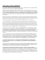
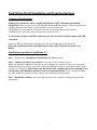
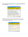
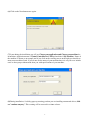
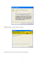
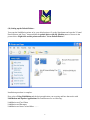
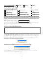
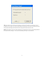
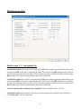
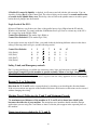
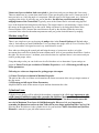
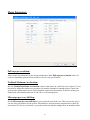
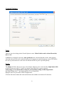
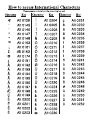
Link
Motion™
by Solustan, Inc.
Tel: 781-449-7666
support @solustan.com
User’s Manual
©Copyrights Reserved 2003-2011
1
SOFTWARE LICENSE AGREEMENT
YOU SHOULD CAREFULLY READ THE FOLLOWING TERMS. YOUR INSTALLATION OF THE PROGRAM
INDICATES YOUR ACCEPTANCE OF THESE LICENSE TERMS.
PLEASE READ THIS AGREEMENT CAREFULLY BEFORE INSTALLING THE PROGRAM. SOLUSTAN, INC.
WILL ONLY LICENSE THE PROGRAM TO YOU IF YOU FIRST ACCEPT THE TERMS OF THIS AGREEMENT
BY INSTALLING THE PROGRAM. SOLUSTAN, INC. PROVIDES THE SOFTWARE FOR TRIAL FOR 15 DAYS
OR 15 LAUNCHES OF THE DRIVER TO PROVE THE FUNCTIONING OF THE DRIVER ON YOUR PC BEFORE
PURCHASING THE LICENSE. ONCE THE LICENSE IS PURCHASED, IT IS NON-REFUNDABLE AND NONRETURNABLE.
These license terms apply to Your installation and use of the program, which program includes copyrighted materials
and programs (collectively referred to as "Program"). This license is granted to You by Solustan, Inc. You may not use
the Program contained in this Package to upgrade any existing Programs that You may have. The Programs contained in
this package are intended only for New Users of LinkMotion and/or MaxMotion and not for any other use.
1. License. This Program is licensed and not sold. Title to the Program does not pass to You. Solustan owns
copyrights in the Program. You obtain no rights other than those granted You under this Program License Agreement.
The term "Program" means the original (including any revisions, enhancements, updates, or the like) and all whole or
partial copies of it, including modified copies or portions merged into other programs. You are responsible for the use
of, and results obtained from the Program. This Program may be used only on one machine at any one time. You may
not reverse assemble or reverse compile the Program, except as specifically provided by law, without the possibility of a
contractual waiver. You may not sublicense, rent, lease, or assign the Program.
2. Disclaimer of Warranty and Limitation of Liability. THE PROGRAM AND ANY OTHER PRODUCT WHICH
WE PROVIDE TO YOU AS PART OF OUR SERVICE ARE PROVIDED "AS IS." EXCEPT AS SPECIFICALLY
SET FORTH HEREIN, NEITHER WE NOR OUR LICENSORS MAKE ANY WARRANTIES, REPRESENTATIONS
OR CONDITIONS OF MERCHANTABILITY, QUALITY, AND FITNESS FOR A PARTICULAR PURPOSE
RELATING TO OUR PROGRAM, SERVICES, AND/OR RELATED PRODUCTS THAT WE OR OUR LICENSORS
PROVIDE.
3. IN NO EVENT SHALL SOLUSTAN BE LIABLE FOR ANY DAMAGES RESULTING FROM THE USE OR
MISUSE OF THE SOFTWARE OR THE ACCOMPANYING MANUAL INCLUDING BUT NOT LIMITED TO
DAMAGES FOR INJURY TO ANY PERSON OR PROPERTY. THE PROGRAM IS DESIGNED TO WORK WITH
MACHINES AND AS SUCH, ANY PART OF THE SYSTEM MAY MISBEHAVE. IT IS IMPORTANT TO TAKE
ALL THE NECESSARY PRECAUTIONS IN OREDR TO AVOID EQUIPMENT DAMAGE AND/OR INJURY.
4. WE DISCLAIM ANY WARRANTY OF TITLE OR OTHER WARRANTIES FOR ANY THIRD PARTY'S
OFFERING(S) OR PRODUCT(S). ALL SUCH WARRANTIES AND REPRESENTATIONS ARE HEREBY
EXCLUDED. WITHOUT LIMITATION, NO WARRANTY IS GIVEN THAT THE PROGRAM OR PRODUCTS
ARE ERROR-FREE.
WE, INCLUDING OUR LICENSORS, DISCLAIM ANY LIABILITY OR RESPONSIBILITY ARISING FROM ANY
CLAIM THAT YOUR ACCESS OR USE OF THE PROGRAM, SERVICE, AND/OR RELATED PRODUCTS WE
PROVIDE INFRINGE ANY THIRD PARTY'S INTELLECTUAL PROPERTY RIGHTS.
IN NO EVENT ARE WE OR OUR LICENSORS ARE LIABLE FOR: A) DIRECT, SPECIAL, INDIRECT,
CONSEQUENTIAL OR INCIDENTAL DAMAGES EVEN IF WE HAVE BEEN ADVISED OF THE POSSIBILITY
THEREOF INCLUDING, BUT NOT LIMITED TO, LOST PROFITS, LOST BUSINESS REVENUE, OR FAILURE
TO REALIZE EXPECTED SAVINGS; OR, B) ANY CLAIMS AGAINST YOU BY ANY OTHER PARTY. This
Section applies to all claims by You irrespective of the cause of action underlying Your claim, including, but not limited
to: a) breach of contract, even if in the nature of a breach of condition or a fundamental term or a fundamental breach, or
b) tort including but not limited to negligence or misrepresentation.
2
In no event are We or Our dealers liable for any damages arising from Your failure to perform Your responsibility in
connection with this Program License Agreement, or arising from any cause beyond Our control, including but not
limited to delay in the performance of Our obligations or misuse of Your User IDs. All limitations and disclaimers stated
in this Section also apply to Our Product Licensors as intended beneficiaries of this Program License Agreement. Any
rights or limits stated herein are the maximum for which we are collectively responsible.
5. Termination. This license is effective until terminated. This license will terminate immediately without notice from
Solustan, Inc. if fail to comply with any of its provisions. Upon termination you must destroy the Software and all copies
thereof, and you may terminate this license anytime by doing so.
6. General. You are responsible for payment of any taxes, including Your personal property taxes, resulting from this
Program License Agreement or Your use of the Program. You agree to comply with all export laws and regulations.
Neither party may bring an action under this Program License Agreement more than ONE years after the cause of
actions arose. This Program License Agreement and all Your rights and obligations are governed by the laws of the
State of Massachusetts.
7. LinkMotion driver software is protected with a software protection key. The protection key is tied to your specific PC
computer using appropriate Microsoft Operating System. If the technology was not available to transfer the license to
another PC, you will be required to buy another license at a full price of the software in case of a PC failure beyond
normal repair. It is very important to safeguard the PC with the license.
8. LinkMotion driver software you purchased can also protected with optionally available hardware ID (dongle) key. If
the ID key fails for some reason, you could return it for replacement. As long as Solustan can identify the key to be the
one issued by us, we will replace it for a fee. On the other hand, if you lose the key, you will be required to buy another
license at a full price of the software. It is very important to safeguard the ID key.
Solustan, Inc. 165 Chestnut St., #200, Needham, MA 02492
Tel: 781-449-7666 Fax: 781-449-7759 EMail: [email protected]
3
LinkMotion Detail Installation and Setup Instructions
Computer Requirements:
Windows XP with Service Pak 2 or higher and Microsoft .NET 2.0 Framework installed,
Parallel Port, Processor speed of at least 800 Mhz, Minimum RAM memory 1 GB or more preferred,
60 MB of Hard drive free space, Screen resolution of at least 800 x 600,
CD-ROM drive is not required, if the driver software was down-loaded from the web site.
CD-ROM drive is necessary, if the software was received on a CD.
Use keyboard and mouse with PS2 connection only. Do not use Keyboard and mouse with USB
connection.
Microsoft .NET 2.0 Framework is available for a free download from the following site:
Microsoft.com>Downloads & Trials>Download Center>.NET Framework Version 2.0 or
Higher.
Installation required for LinkMotion VC:
Part 1 - Second part is installation of LinkMotion VC driver software.
Part 2 - Software License Code procedure is necessary for full working license.
When you install the LinkMotion software on your computer it is good for 30 days or 30 executions.
Within this period you need to get a license code from Solustan to make it a permanent license for the
computer of your choice. Please make sure and install on the computer that you are planning to use
for long term. All LinkMotion product Licenses are non-transferrable. Price is subject to change
any time. Additional software licenses can be made available for an extra charge.
Part 3 - Installation of Fonts is necessary and provided to the customers with Engraving machine
upgrade kits.
4
Part 1 - Installation Procedure for LinkMotion VC driver version 2.7 or
higher:
Note that you must have administrative privileges on the computer in order to install LinkMotion.
Most of the installation process is self-explanatory with following screens. You can stop the installation
at any time by clicking "Cancel".
If you have received the driver software on a CD then follow steps from (1A). If you have down
loaded form the web then go to step (1B). Go to step (2) if you already installed the driver for the
hardware key (dongle).
(1A) Insert the LinkMotion installation CD into your CD-ROM drive. If the Auto-run feature is
enabled, Windows will start the Installation automatically. If the Auto-run feature is not enabled, browse
the CD drive in Windows explorer and double-click on the "Launcher.exe" and installation will begin.
or
(1B) After downloading, unzip the files and save them by creating a folder name LinkMotion. Now
double click on the file name Launcher.exe and installation will begin.
(2) Click on the Next Button.
(3) Click on the Next Button.
5
(4) When you get to the License Agreement dialog (see above), you must read the agreement. If you
agree, go ahead and click the radio button, "I Agree" for the installation process to continue. Then
Click on the Next Button.
(5) After you have read and agreed to the License Agreement, you will be asked to specify the
installation folder. In most cases you can leave this at the default value. You will also be asked to
specify who will be able to run LinkMotion on this computer. In most cases you should specify
"Everyone" and then Click on Next button.
6
(6) Click on the Next button once again.
(7) Later during the installation you will see Choose your application and Choose your machine for
installation. Application name is Virtual Controller for CAM and machine is My Machine. Name of
the machine is shown as an example and if you click on the scrolling arrow on the right you should see
many more machines listed. If you do not see the name of your machine then it is easy for us to include
once we have proper information from you with specifications of your machine.
(8) During installation, if a dialog pops up warning you that you are installing an untested driver, click
on "continue anyway". This warning will be removed in a future release.
7
(9) Click on "Close" when the installation is complete.
Icon shown above should show up in system tray at the bottom right.
8
(10) Setting up the Default Printer:
You want the LinkMotion printer to be your default printer. Go to the Start button and open the "Control
Panel>Printers and Faxes" menu and find the printer driver with My Machine name as shown in the
picture below. Right click on this printer and select "Set as Default Printer".
Installation procedure is complete.
Now refer to Using LinkMotion and the design application you are using and how that works with
LinkMotion and Popular Applications. Document names are as following:
LinkMotion and Corel Draw
LinkMotion and Illustrator
LinkMotion and Auto Cad and More …….
9
Uninstalling LinkMotion:
Please make sure of the following before you uninstall:
Your specific machine related settings are saved as LinkMotion.ini file. This file can be saved from
General Options Menu and simply click on the Save button and give whatever name you prefer. You
can also navigate where in your hard drive you want to save it. Different users can save under different
names. Similarly you can Load that file back after another installation of LinkMotion by going to the
General Options menu and clicking on the Load button. Navigate to the file from your computer where
you saved it earlier. Restore Default button allows you to load default installed INI file that is supplied
with LinkMotion. It is very important to exit LinkMotion applet and Re-launch the applet when
you make any changes for it to be effective.
Uninstall LinkMotion Procedure:
Make sure the LinkMotion applet is closed. Open the Start menu and select the Control Panel.
Double-click on Add or Remove Programs. Look for LinkMotion entry in the list and click on that.
Select "Remove" and answer "Yes" when it asks you if you really want to remove LinkMotion.
LinkMotion.INI file (configuration file) does not get deleted with uninstall
procedure. If you want to delete your existing INI file following is the procedure:
In the hard drive Find folder name Document and Settings> Folder with users (your own name)
name> Folder name Application Data> Folder name Total Graphics Network> Folder name
LinkMotion> LinkMotion.INI. Delete this file.
Re-Launch LinkMotion:
It is extremely important to Re-Launch LinkMotion if you replace or change LinkMotion.INI file
for it to be effective.
Exit the LinkMotion (icon) applet by right mouse click from the systems tray at the bottom right.
LinkMotion icon should go away from the systems tray.
Now launch it back again by following and selecting the path Windows Start button>Program
Files>Solustan>LinkMotion by the arrow of your mouse.
LinkMotion icon should appear again in the systems tray at the bottom right.
10
Part 2 – Software License Key Procedure:
We welcome you for trying out our LinkMotion driver software. You will see the following message on
the screen when LinkMotion is launched from the systems tray every time when you are using the
program as demo.
Click on the Enter key button, whenever you decide to purchase or you have purchased it and you are
ready for full license key. Enter Key will open following dialog box and show the Hardware
fingerprint of your computer.
You need to provide us the proper information for Hardware fingerprint, Business Name, valid email
for Business along with the LinkMotion version and operating system you are using. Fill out this
information in each respective boxes, save the file and email it to us at [email protected]. Solustan
is not responsible for any incorrect Hardware fingerprint code you provide. Please double check
this information before you send it to us. Software license working with Hardware fingerprint and
matching code provided by Solustan, Inc. is intended to work only on the computer with the proper
hardware fingerprint. Key Code will not be generated for any incomplete information.
All LinkMotion product licenses are non-transferrable. User will need to buy another license for
another computer. Additional license can be made available for an extra charge.
Hardware fingerprint:
Name: (Business name or Computer user’s name)
Valid email for Business or User:
11
Your Operating System:
Win 7 64
Win 7 32
Win XP
Your LinkMotion Application:
LinkMotion USB
LinkMotion Lite
LinkCAM M&G
LinkMotion VC
LinkMotion VC-Laser
LinkMotion Galvo
LinkMotion HPGL Eng.
LinkMotion HPGL Vinyl
LinkMotion Leetro
LinkMotion USB and LinkMotion Lite users need to verify Serial number of the USB controller
card. Launch your LinkMotion application and select the Help tab(menu). Last thing at the bottom right
it displays the serial number for the USB Controller. Please write this serial number in the box below.
USB Controller Serial Number:
After you send us all of the information in above boxes, we will send you the customized Key Code.
This key code is long text containing numeric numbers as well as alphabet letters.
Key: (Key Code for LinkMotion License)
We highly recommend that you simply copy and paste this in the Key section by bringing back the
same Enter Key screen. Click OK and you are ready to use your LinkMotion driver software license.
If you did not purchase within 30 days or 30 launchings you will see a last reminder as seen in the
following picture. It will be best to purchase at this point.
Once the trial period of LinkMotion expires, you will see the following message.
Click on the Enter key will always give you the Hardware Fingerprint and you can purchase the
software any time if you were using the trial version.
12
Part 3 - Install Engraving Fonts: (Rotary Engraving machine users only.)
Although, any TrueType font can be engraved under the LinkMotion application, Solustan provides
traditional engraving fonts. All the engraving fonts are not only designed as TrueType fonts but they are
also designed such that engraving bit does not lift up to finish any alphabet character once it starts. We
call them Non Lift Fonts. It will engrave faster and smoother. Multi Line fonts are designed and
Optimized to work with 0.5 inch or higher sizes.
Fonts provided with the LinkMotion driver software (for engraving customers) has the folder name
MaxFonts (Basic Fonts). Fontpak is the optional fonts and you will see this folder only if you have
purchased optional fonts. Customer using Braille option should see a folder name Braille Fonts.
Make sure there is no application launched before starting to install the fonts.
(1A) If you have not removed your CD LinkMotion Installation you can move to the next step. If the CD
was removed you need to put CD back into the CD drive. It will start installing again and you need to
click cancel for automatic Installation.
or
(1B) If you received this by internet when you unzip the software you should see appropriate fonts
folder names as described earlier.
(2) Now go to the Control Panel. On the left side on the top you will see Switch to Classic View.
Click on it. Select Font folder from the list of items you see on the right side.
(3) Select Install New Fonts from the File menu.
(4) Under Driver section select Your CD drive (D or E) if you received the software on CD or your
hard drive C if you down loaded the software from internet.
(5) Under Folder section open MaxFonts folder. Select all fonts from the List of Fonts on the top and
Click OK.
(6) You are done with the Installation. If you have purchased other optional fonts you can install them in
the same way.
Please follow the keyboard layout pictures to enter proper text from each keyboard layouts shown in the
Fonts section of the document Using LinkMotion manual.
13
LinkMotion Virtual Controller for 3 or 4 Axis:
The LinkMotion driver comes with a small application that resides in the System Tray. The System Tray
is the lower right bar of the Windows screen. Double click on the LinkMotion icon to bring up the
application. Based on the selection, the Control Pad will show up in English, Spanish, or symbols.
Control Pad can be designed easily into any of the languages of the world.
Your computer should have Windows XP operating system with Service Pak 2 (SP 2) installed,
one parallel port (on original mother board) and one USB connection. Also you should install
Microsoft .NET Framework Version 2.0. This is available form Microsoft’s web site for you to
download freely:
Microsoft.com>Downloads & Trials>Download Center>.NET Framework Version 2.0
Do not use Keyboard or mouse connected with USB connection. Use PS2 connections.
Install LinkMotion following the instruction that you received with your LinkMotion CD. First
part of the installation is only for LinkMotion I.D. Key driver for customers who purchased the
hardware key option (customers with software protection only will not have this driver) and the
second part will be the LinkMotion driver application. Make sure to select proper application
and your machine name during the last part of the LinkMotion installation.
Warning for Control Pad:
Please avoid using the mouse after you have sent the job for the output. Once the
job is done, your mouse should be available for use. Use the ‘Zero’ or the ‘Space
Bar’ key on your keypad to Pause. You will see a message box asking you if you
want to Continue or Quit the job. (Some times this message box is in the back of
your Control pad and you can bring it to the front simply by clicking on the system
tray’s active LinkMotion application.) At this point you can go to LinkMotion and
change the speed or depth in the materials menu, click apply and then click Yes to
continue the job or No to stop the job completely. Keep in mind that if it is in the
'Move Mode' between the shapes or letters, it may not pause. When jogging the
machine do not press three keys together, it may cause undesirable results. Some
times pressing two keys together for both X and Y movements can cause machine to
continue moving in one direction even if you are no longer pressing the key.
Pressing the same key again or the opposite direction key should stop this
unnecessary movements.
Do not use the arrow keys elsewhere on the keyboard in place of the Control Pad
keys.
Once a job is sent or you have activated the LinkMotion applet then it shows up in
the bottom bar where active applications are displayed. If LinkMotion was already
in active mode and if you launch again from the system tray on the bottom right
14
Control pad of LinkMotion does not become active. User need to either launch it
again from the active mode or needs to close it and re-launch it to make it active.
LinkMotion.INI file can be found as follows:
In the hard drive Find folder name Document and Settings> Folder with user’s(your
own or business name) name> Folder Application Data> Folder Solustan> Folder
LinkMotion> File name - LinkMotion.INI
Open LinkMotion.INI file by double clicking on the file. It is a text file. You will see
all the different machine names at the beginning. Specific machine related controls
are further down in the file. Find the specific settings for your machine and you can
make changes there. Remember to save the file after you make changes. Also,
remember to Re-Launch LinkMotion for your changes to take effect.
Re-Launch LinkMotion:
It is extremely important to Re-Launch LinkMotion if you replace or change LinkMotion.INI file
for it to be effective.
Exit the LinkMotion (icon) applet by right mouse click from the systems tray at the bottom right.
LinkMotion icon should go away from the systems tray.
Now launch it back again by following and selecting the path Windows Start button>Program
Files>Solustan>LinkMotion by the arrow of your mouse.
LinkMotion icon should appear again in the systems tray at the bottom right.
15
Control Pad in English:
The Control Pad is operated using the numeric keypad, the right side of the extended PC keyboard.
Click on the Apply button after any changes you make on any of the Tabs (Menus). Changes are
effective only when you click on these buttons.
Home (Limit) switches (Green or red lights) show up at the top of the Control Pad for each axis. If
switches are present and properly configured, it will show green color when not tripped. We protect you
from driving into the end of an axis where you may have tripped the Home switch already. Move the
table in any one of the axis until the switch is tripped, the green color will change to red. Once the
switch has Settings for the switches are in the Origin Setup menu. Sometime Z axis is either Solenoid or
there may not be a home switch in Z axis and in that case you need to go to the Origin menu and under
Home switches uncheck Z axis Enabled.
Reset Counter – Basic function of this is to Reset Counter to 0 value for each X, Y and Z axis
positions. If you move the tool any where on the table, the X, Y and Z the counter will display the actual
position of the tool. If you then click on the Reset Counter it will make all the display values to 0, 0, 0.
Machines without the Home switches or selecting a new staring position on any machines are some of
the useful functions of Reset Counter button.
16
Move To 0,0 – Clicking on this button will make your machine move your X and Y position to 0, 0
location if the counters show values other than 0, 0. This is a useful function for resetting back to the
start position for the machines without the Home switches.
Clicking on the Solustan logo will take you to Solustan web site, if the computer is online and connected
to Internet.
All the blue colored keys are designed to move X, Y, and Z axis with respective direction. Following
are the keys for each axis X left (4), X Right (6), Y Up (8), Y Down (2), Z Up (-), Z Down (+) and
Move Fast (5).
Move Fast Key (5) is pressed along with X or Y key movement to make it move faster. For faster
movement you also need to have faster speed in the Move section of the materials menu. Move value is
responsible for two functions. One function is fast jog speed and second function is tool up speed when
it lifts up between the shape while doing a job.
Z Ref key (*) is clicked when the tool is just touching the top of the material. LinkMotion will
remember the reference surface for the job. It will use the Z reference to calculate the moves in the Z
axis for the depth and lift as it processes the job. If your machine has the home switch for Z axis and if
it is activated in LinkMotion, Z Reference value is automatically calculated. If your machine does
not have the home switch then you can declare the Z Reference value in the Origin setup in the Z
offset for Start Position and it will go up by that distance with the Z Reference Key. If you traveled
in X and Y direction to do the Z Reference you should go back to home position only by clicking
on the button on the Control Pad ‘Move To 0, 0”.
If your Z stroke is 3 inches or more and you do not care to travel the full stroke while seeking the
home switch during homing operation, you could declare Z home switch not enabled and declare
your own Z-up stroke in the Z-offset in start position of Origin setup menu.
HOME key (7) will move the machine to its Home position, if the machine is equipped with home
switches. Machines may have home switches in X and Y axis or all the three axis. Home key is used
after you do your Z Reference.
I/O Keys (1), (3), (. or Del) and (9) are available for I/O 1, I/O 2, I/O 3 and I/O4 controls. These could
be used to control Z axis movement in case Z axis is not motorized but it is solenoid and is controlled by
air valve, for example. Can also be used for lubrication of tools, vacuum control, laser control, red
diode, air, water etc. Each click of the keys can toggle the I/O position. User can set to make the action
momentary or toggle by way of settings in the LinkMotion .INI file.
Spindle Control for CNC/Engraving type application or Air Control for Laser type application Key (9) I/O 4 is used to control spindle motor or air in case of laser application. Each click of the keys
will toggle the I/O position.
I/O keys to be either momentary or toggle keys find the following lines in LinkMotion.INI file and
in the area of your machine name selection:
17
Key1Toggle=0
Key3Toggle=0
Key9Toggle=0
KeyDeleteToggle=0
These lines control the toggle or no toggle nature of the four I/O keys on the Control Pad. The four
keys correspond to keys 1, 3, 9, and Del. Any key with a declared value of zero is a momentary key
while a declared value of 1 becomes a toggle key.
The big 0 (zero) or Space bar key is available to stop processing of the job anytime.
When job is being processed it is very important to remember not to touch the
mouse and the rest of the keyboard.
Num Lock and \ keys are available only when machine is in motion.
These keys can decrease or increase the speed of the X, Y movements of the machine. Do not keep this
key pressed for long time. Simply press and release gently each click of the key will decrease or
increase the speed according to the settings in the LinkMotion.INI file. OnTheFlySpeedChange=4 is a
default value in the INI file. This number works in percentage value of the original speed specified in
the Job feed rate of the Materials menu. When the machine is in motion user can decrease the speed
by pressing Num Lock Key. Similarly user can increase the speed by pressing the / Key. For safety
reasons increasing the speed will never go above the speed declared in the Job Feedrate of the
Material Properties. Once the job is done the speed again goes back to what is declared in the Job
Feedrate of the Material Properties.
18
Control Pad in Spanish language:
Go into General Options menu. Look at Control Pad Labels. Arrow to the right will show you the
choices you have. Here select the Spanish Control pad and click on Apply button. Now you will see the
Spanish control pad.
19
Control Pad with Symbols:
Go into General Options menu. Look at Control Pad Labels. Arrow to the right will show you the
choices you have. Here select the Symbol Control pad and click on Apply button. Now you will see the
Symbol control pad.
20
Materials Properties Menu:
Material:
Pull down the Material Properties menu to observe a selection of various materials. Pre-select the
values of speed and tool positions for each of the materials. The default values are simply that.
LinkMotion can be employed to work with many different types of machines. Hence, there is no single
value appropriate for all different machines. User’s experience will dictate the values for his/her
machines.
The values can be inches per second or millimeters per second or centimeters per second. General
Options menu allows you to make your selection for this measure of units.
Per-Pen/Color Settings:
Jobs can be designed in color and job feed rate speeds can be defined as percentage of declared values
for each of the color. One of the applications of this feature is to design the same job in different colors
on different layers and sequence the layers appropriately.
Following are the color/pen values for the LinkMotion printer driver. RGB values are given in percent.
Pen number
--------------1
Color
-------Black
R
--0
G
--0
B
--0
21
2
3
4
5
6
7
8
9
10
Red
Green
Blue
Cyan
Magenta
Yellow
Orange
Brown
Purple
255
0
0
0
255
255
255
128
128
0
255
0
255
0
255
128
0
0
0
0
255
255
255
0
0
0
128
If you did not create a color palette with the above RGB values, our understanding of the way GDI
handles this is that GDI will convert the object's color to an RGB value using whatever color correction
model is in effect, then will do a least-squares fit to the 10-color palette (whichever of the 10 colors is
closest to the color of the object on a least-squares bases will be the color that is sent to the printer
driver).
Tool Speed:
Job feed rate is the speed when the tool is engaged into material and working. Bringing your arrow on
the number that shows Job Feedrate (100%) for each pen and Double clicking on the number should
open a box that will allow you to change this number. If your job federate in tool speed is 2in/sec and
you make the red pen to give output at 50% then job should run at 1in/sec.
Jog speed is when the user is jogging the machine with the help of Control Pad.
Move speed has two functions, it is the speed when the tool is retracted and the machine is moving to
the next shape after finishing the previous one and it is also used for fast jogging (holding down fast
key while keeping the directional key pressed).
User can set up separate speeds for Z feed up and Z feed down.
Cutter:
Depth is the value declared for tool to travel in the material. Once the top of the material surface is
determined, depth value controls the movement of the tool in the vertical axis.
Maximum depth per pass is the value declared if you wish to do your job in multiple passes. For
example if you have selected 0.15 in to be your Depth value and you want to do your job in three passes
you can declare 0.05 in value for Maximum depth per pass and your job will be done in three passes.
When you send the job you should see the dialog box for Pause Between passes. User can select to
pause between the passes or continue without the pause in the dialog box when doing the job with
multiple passes as shown on the screen below. Your tool will always return to 0, 0 for X, Y position
(Regardless of weather you have checked or unchecked in the origin setup for Return to 0,0 after job)
and then do the next path. If you declare 0 value in multiple pass it will always do the job in one pass.
22
Lift is the value for tool to lift between the shapes to do the job. If you have several inches of travel
available for Z axis then it saves time to plug in the lift value where it does not travel all the way up for
Z axis between the shapes and instead it travels only by the Lift value and saves time.
Dwell is the amount of time in seconds and fraction of seconds the tool will stay at the same position in
the material before making X, Y move and after finishing the shape to cut the material.
23
Machine properties:
Enable output 1, 2, 3 and Spindle/Air:
If Enable I/O control 1 is checked, it will turn the I/O ON while cutting/engraving a shape during a job
and turn itself OFF at the end of completing the shape. The I/O will stay OFF during the traverse/Move
motion to the beginning of the next shape. You can test the operation of the I/O by either clicking on the
Key 1 button with a mouse or depressing the key on the Control Pad.
If Enable I/O control 2 is checked, it will turn the I/O ON while cutting/engraving a shape during a job
and turn itself OFF at the end of completing the shape. The I/O will stay OFF during the traverse/Move
motion to the beginning of the next shape. You can test the operation of the I/O by either clicking on the
Key 3 button with a mouse or depressing the key on the Control Pad.
Z axis can be selected as solenoid or air controlled. It may be attached to I/O 1 or I/O 2.
If Enable I/O control 3 is checked, it will turn on and off with the job execution. You can check by
clicking Key Del (.) on the Control Pad.
24
If Enable I/O control 4 (Spindle) is checked, it will turn on and off with the job execution. You can
check by clicking Key 9 on the Control Pad. The value of delay can be entered in seconds and fraction
of seconds in the Spindle Delay area. This delay value will allow the spindle motor to reach its speed
before the tool plunges into the material.
Logic levels of the I/O’s
Microsoft Windows sets all the active lines of the parallel port as logic High when the PC and the
Windows are launched. To comply with that, LinkMotion uses Logic Low to activate any of the I/O’s.
We set up a line in the INI file called,
Control Port Default=4 (This makes logic High) or
Control Port Default=11 (This makes logic Low)
If you need to invert any of the I/O lines, you could do that by declaring different values for the above
setting. Following values will give you the following results:
Control Port Default=
I/O1 (Pin14)
I/O2 (Pin1)
I/O3 (Pin17)
I/O4 (Pin16)
1
L
H
H
L
2
H
L
H
L
4
H
H
H
H
7
L
L
H
H
8
H
H
L
L
11
L
L
L
L
15
L
L
L
H
Safety, Limit, and Emergency controls
Pin 15 on the parallel port is available for connecting safety, limit, and emergency switches. We will
expect Logic 0 on pin 15 for the machine to operate normally. When we see logic 1 on pin 15, the
job will be aborted or will not start. Once job is aborted, it cannot be recovered. It has to be restarted.
We feel Logic 1 is failsafe and requires active response from the safety apparatus for it to work properly.
Reverse X, Y, or Z direction:
Directions for X, Y and Z can be set properly here by checking or un-checking the direction button.
If the axis movements are opposite to the intended directions, the direction or directions can be reversed
without changing the wiring.
Machine Travel (Table size) for X and Y and Maximum Z travel:
The maximum travel distances of the machine in X, Y and Z axis is shown here which is also
known as the table size of your machine. The maximum travel numbers should match the Design
applications you are using like Corel Draw or Auto Cad for the job to appear in the expected place on
the machine.
Linear travel per revolution for X, Y, and Z:
25
Linear travel per revolution (lead screw pitch) is shown here and you can change this if necessary.
There are unknowns in a system from time to time. These are the pitch of the screw (2 turns per inch, 5
turns per inch, etc.), full step angle of a step motor (200 full steps for 360 degree turn, etc.), and micro
stepping of the driver. If you know any two of the three, the third one can be determined using
nudging feature of the Control Pad. Typically, most of the Control Pad is activated using physical
keys of the keyboard and using them with fingers. The nudge feature is activated using a single click of
the mouse on the appropriate key on the screen. Nudge a distance by declaring the distance in the
General Options. Next, measure the actual distance moved by the machine. Make the necessary
correction of the value for the unknown parameter until you get the desired distance by nudging.
Machine setup Test:
There is one simple test you can do using the nudge value in the General Options tab. Default nudge
value is 1inch when you install LinkMotion. User can change this nudge value (0.25 or 0.5 inches) for Z
axis if your machine is designed to travel very small distance overall.
Now when you bring up the control pad and bring the arrow of your mouse on the x axis right
movement arrow and click with the left mouse button and X Axis of your machine should move 1inch to
the right. If it does not move 1 inch then your values declared as explained above is not correct and you
need to get the proper values.
Using that nudge value you can do this test for all of the three axis to determine if your settings are
proper in Linear Travel per revolution of Machine Properties as well as Microstep per full step in
Motor parameters.
Following two values are important for getting proper size output.
(1) Linear Travel per revolution in Machine Properties
The pitch of the screw in all three axis determines the linear movement of the axis per single rotation of
the step motor.
(2) Microstep per full step in Motor Parameters
Amplifier Drivers used for the motors of your machine determine this value.
Cylindrical Axis:
Cylindrical axis choices will be offered if the machine is equipped with it. It is very important to quit
and Re-launch LinkMotion applet after you make this selection. Maximum Travel size of the table
in X or Y will change when you Enable Cylindrical Axis Support. You do not need to enter this
new size in Maximum Travel area in LinkMotion applet. However, it is very important to
remember the dimensions and create that Table size in your design applications like Corel or Cad.
Selecting X or Y whichever is the cylindrical axis for your machine. Motor Gear Ratio and Job Piece
Diameter is entered for your job in the bottom section.
26
Motor Parameters:
Full steps per revolution:
Above values are determined by the motor manufacturer. Enter Full steps per revolution values for
each axis depending upon the motor and the lead screw size specifications.
Toolhead Maximum Acceleration:
Declare Toolhead Maximum Acceleration values for the motors in each of the axis in in/seec^2. You
may need to adjust this numbers to get proper acceleration constants for smooth motion. Check with
your machine manufacturer for the correct numbers required for the machine. In absence of that, you
should start with a number between 25 and 100 as a safe starting point.
Microsteps per every full Step:
Set the Microsteps per every full Step for your system for each of the axis. This is necessary only if
you are using step motors in your system. This number is derived from the Amplifier driver used for
your motors. In case of servo motors, you need to make sure that the multiplication of numbers in this
27
area as well as in the number of full steps per revolution of the motor in the Motor parameters match
your encoder number for the feedback. Generally, it would be a good idea to declare number 1 as the
number in microsteps per every full step and the encoder resolution number in the number of full steps
per revolution in the motor parameters location.
Maximum Motor RPM:
Maximum Motor RPM number should be selected by the specifications given by your motor
manufacturer.
Machine setup Test:
There is one simple test you can do using the nudge value in the General Options tab. Default nudge
value is 1inch when you install LinkMotion. User can change this nudge value (0.25 or 0.5 inches) for Z
axis if your machine is designed to travel very small distance overall.
Now when you bring up the control pad and bring the arrow of your mouse on the x axis right
movement arrow and click with the left mouse button and X Axis of your machine should move 1inch to
the right. If it does not move 1 inch then your values declared as explained above is not correct and you
need to get the proper values.
Using that nudge value you can do this test for all of the three axis to determine if your settings are
proper in Linear Travel per revolution of Machine Properties as well as Microstep per full step in
Motor parameters.
Following two values are important for getting proper size output.
(1) Linear Travel per revolution in Machine Properties
The pitch of the screw in all three axis determines the linear movement of the axis per single rotation of
the step motor.
(2) Microstep per full step in Motor Parameters
Amplifier Drivers used for the motors of your machine determine this value.
28
Origin Setup:
Go Home After Job:
If you have not checked this box then after finishing the job the tool will travel up on Z axis and stop at
the position where it finished the last shape. It does not move the X and Y position. It does not go to the
start position. Checking this box makes your tool go back to the starting position (parking position)
for X, Y and Z axis. Most of the time parking positions are 0, 0 for X and Y. If you have the need to
sense the Home switches again then you need to make sure your surfacing value in the Z axis (Origin
Setup and Z offset value in Start Position) is proper and then click on the Home key on the control pad
and that will place you tool in the Home position. If you need to change the surfacing value then you
need to surface the tool again and then go home.
Disable Home (Limit) Switch:
Checking this box disables the home switches. Un checking the box activates the limit switches. If
limit switches are present, pin numbers need to be assigned in home switch wiring section where the
switches are connected to the computer. It is also important to declare the logic level of the switch in
normal conditions high or low.
29
Home Switch Position:
This is the parking position of the tool of your machine. Bottom Left and Top Left are the choices.
Top Right and Bottom Right are not available at present.
It is important to understand the setting of the origin for the machine. If the machine has home switches,
it will have a defined Home position. It should be selected. The offsets from the limit switch sensing
serve two purposes:
A. It is advisable to get off the switch once sensed. The offset value will allow the machine to move
back by the declared distance after reaching the switch.
B. The offset values can be adjusted to get to a specific position such as the very corner of the table
where the user may want to start every job.
C. This position shall be recalibrated every six months or anytime the sensor is replaced.
Homing Speed:
The Homing speed for finding and going Home is different than the jogging or move speed.
LinkMotion forces the machine to go Home twice when asked to go Home. The Home key is key 7 on
the Control Pad. The first time the machine travels at a higher speed. Once reaching Home the first
time, the machine travels back into the working area of the table and hunts for Home again at a slower
speed. This will allow the table to get to the exact Home position every time.
Start Position:
Bottom Center, Bottom Left, Bottom Right, Center, Top Center, Top Left and Top Right are the
choices.
If your Home Position and Start Positions are the same following are the selection necessary:
Top left and Bottom left are the only two home positions supported at this point if your machine
has the home switches.
Home Position Selection
Start Position Selection
Bottom Left
Bottom Left
Top Left
Top Left
Job start position can be different than the Home position. Job start position may be,
- Where the jig is positioned (Home Position)
- Center of a machine in case of a vise type machine with offset values in X and Y where both
jaws move
- Top center of a machine with offset value in X only in case of a machine where only bottom
jaw moves
In above situations and others, it is necessary to select Start Position and declare offset values for X and
Y appropriately.
30
If you suspect that there is a problem with one or more limit switches and it is hindering your
production, check the Disable home (limit) switch box at the top. This will allow the operation of the
machine while the limit switches are being investigated.
Home Switches:
Home Switches for each axis can be selected individually by selecting the pin numbers. This depends
on how your machine is built and wiring is connected. Some machines have home switches for all three
axis and some have for X and Y but not for Z axis. Make proper selection for your machine.
Home Switch Polarity selection is available for Normally High or Low and it depends on how the
wiring is done for your home switches. LinkMotion will sense those switches and show you green
lights on the control pad (next to X, Y and Z movement boxes) when we sense proper switches. If you
do not know how your machine is wired then try selecting one after another and when the lights are
green you have made the proper selection.
Select Not Present when machine you are using does not have home switches.
31
32
General Options:
Units:
There are just a few things in the General Options screen. Units of choice can be selected from inch,
mm, or cm.
LinkMotion is designed to provide a slow speed move for a declared amount of time, when jogging.
After that, the tool will move at the declared speed of jogging in materials property screen. This allows
the user to position the tool or the laser red indicator diode at a precise position quickly.
Nudge:
The Nudge will allow the axis to move a fix distance when any axis is moved with a single mouse click
on the keys that move the X, Y and Z axis when Control Pad tab is open or selected.
Using nudge you can do the basic testing for your machines settings in following manner:
Set up the Nudge to be 1” and Apply and save. Go to Control Pad.
Bring the arrow of your mouse on the X-Right arrow.
Click the left mouse button and watch and measure the machines movement in X direction.
33
If it moved 1” to the right then your settings are proper. If it moved less or more distance then 1” you
need to change linear travel per revolution in Machine properties as well as check your Microsteps
per full steps (dependent upon drivers used for the motors) declared in the Motor Parameters.
Port:
Port: LinkMotion will send the jobs to the selected port. If it is used for Virtual Controller applications
where machine is connected to parallel port. You can specify the port’s Base address.
Control Pad Labels:
Control Pad Labels: Arrow to the right will show you the choices you have. Here select the English,
or Spanish or Symbol and click on the Apply button. Now you should see the control pad you have
selected.
Enable Braille support:
Enable Braille support is an optional feature and it is designed to drill dots. This is used for creating
Braille signs. Adot is the font we provide when Optional Braille support is purchased. Selecting this
option makes your tool travel to the begin point of each shape and go down to create a mark or a hole
and go back up and go to the begin point of the next shape.
OEM Settings:
Hide OEM setting is for OEM customers only and it hides some of the control pad settings as
requested. It is controlled by a line User Type=0 or 1 in the LinkMotion.INI file. One value enables
OEM settings and Zero value displays all settings. Checking the button in the General Options menu
will hide some of the settings and user needs to change the value back to Zero in the LinkMotion.INI file
manually to bring back those hidden settings.
Save Settings:
Save:
Once the machine is properly configured and is working well, it is advisable to Save the settings on
the hard disk drive. This is saved as LinkMotion.INI file.
LinkMotion.INI file is located on your hard drive C:\ Document and Settings> Folder with
computer users name> Folder name Application Data> Folder name Solustan> Folder name
LinkMotion> LinkMotion.INI.
Click on the Save button and it will ask you to give a file name. Make sure to remember the file name,
and where you are saving it. You can navigate on your hard drive where you want to save. You can also
rename the file with what ever is easy for you to remember. Mostly our customers rename the file with
their machine name.
Load:
34
In case the LinkMotion needs to be loaded again from the CD supplied by Solustan, or you need to
load upgraded version the user will be able to reload all the settings with your .INI file without
wasting any time. For loading the settings back select Load button and navigate to the saved .INI file
and click on Apply and OK. Now click on the right mouse button when you are on the LinkMotion
appellate and exit the program. Go to the start button and launch back LinkMotion. You should see all
your saved settings here now.
Restore Defaults:
Clicking on this button will load default LinkMotion.INI file that we supply with the LinkMotion
driver.
It is very important to exit Link applet and Re-launch the applet when you change
and select another INI file for it to be effective.
LinkMotion driver mode of operation:
General purpose mode – This is loaded by default. This mode is used when you use Corel, AutoCAD
type of design softwares and use LinkMotion to send files to your machine. Only MaxMotion users do
not need to use this mode.
MaxMotion mode – This mode is used when you use MaxMotion virtual controller applications.
MaxEng, MaxCAM, MaxMark, User needs to change this after you install LinkMotion. After
changing to MaxMotion mode you need to apply and close the LinkMotion applet. Exit LinkMotion
applet by right mouse click. Relaunch the LinkMotion applet. This is necessary only when you change
the mode. Not switching to this mode can result into undesirable results.
Font Height Control is necessary for working in the MaxMotion applications. Please follow the
instructions below for correct font size output.
Pass through mode – This mode is no longer supported and it will not show up in newer versions.
This mode is used when you use MaxMotion HPGL and Unica applications. MaxHPGL, MaxUnica.
User needs to change this after you install LinkMotion. After changing to Pass through mode you need
to apply and close the LinkMotion applet. Exit LinkMotion applet by right mouse click. Re-launch the
LinkMotion applet. This is necessary only when you change the mode.
Font Height Control is necessary for working in the MaxHPGL and Unica applications. Please follow
the installation instructions for correct font size output.
Setting up MaxMotion font sizes:
Because of differences in the way Windows 98 and Windows XP handle screen resolution, you may
have to adjust the way MaxMotion displays and handles fonts. To see if you need to make an
adjustment, start one of the MaxMotion applications, pull down the "Job Design" menu, and select
"Fonts ". Choose the A3Roman fonts, set the size to 1 inch, and click OK. Now choose the font tool and
35
type an uppercase T and an uppercase E. Now choose the arrow tool and select the text you just typed;
you will see a blue box around the text. The text should be the same height as the box, like this:
These are cases of incorrect font sizes:
36
If your fonts are too big, you need to make the Font Size factor larger. If your fonts are too small, you
need to make the Font Size factor smaller. As an example if font size shown in the picture above that is
smaller you need to enter .80 or for the larger you need to enter 1.25 as a value. To change the Font Size
factor, launch LinkMotion, select the "General Options" tab, and select the Font Size factor you want.
There are three preset values you can try (Normal, Higher, and Lower) or you can enter your own
custom value. Remember to click "Apply" and "OK".
You must exit from your LinkMotion and MaxMotion application and restart it before the new setting
will take effect.
After this setup you can start using MaxMotion Applications.
Using MaxMotion application with LinkMotion:
To run the legacy MaxMotion applications, go to the Start Menu, find the Solustan menu, open the
MaxMotion submenu, and click on the MaxMotion program you want to run.
MaxMotion for XP does not support the Print command to print to a regular Printer.
Once you design in MaxMotion application you can use windows Print Screen key command, Paste it in
the Paint Program and Print to a regular printer.
LinkMotion does not support dot design from MaxMotion for output. Scoring output from
MaxEng application is not supported. Bridge, lead in and 3D output features from MaxCam
application are not supported. Bottom left is the only home and start position supported from
MaxCam. Dotted output for Marking application is also not supported.
Instructions for I.D. key Upgrade:
This is used only if you have hardware key.
37
This is required only when you need to upgrade the features offered or upgrade to use with the
new version of LinkMotion or upgrade the number of executions for the I.D. Key.
To upgrade your I.D. key you will receive a code as a text file from us.
Note pad or Word pad type of utility should open this code.
Simply highlight the code with a cursor. Right mouse click and select Copy.
Now launch LinkMotion Icon. Click on the General Options menu. Click on the button Update I.D.
Key. A dialog box will open. Right mouse click inside the Authorization Code box. Select Paste. Click
OK. Click on OK in General Options menu.
Now right mouse click on the LinkMotion icon and select Exit.
Go to the Start button. Select All Programs. Select Solustan folder and select LinkMotion application.
Now you will see a LinkMotion Icon on the bottom right again. You are all set to work with your
updated I.D. Key.
38
Engraving Fonts:
39
40
41
42
43
44
Application Compatibility with LinkMotion:
Go to www.solustan.com/support and download instructions for the appropriate design application you
might be using. Some applications have their own limitations and mostly it is listed in the document.
We are adding information as we test with respective applications.
Solustan tests the primary function of accepting hair lines (vector lines) from the third party application
software to make the vector moves on the machine using LinkMotion driver. Solustan may test
additional functions. However, it is not a detailed testing. The developer and marketer of the third party
software make changes to their applications quite often. It is the responsibility of the user to make sure
that the necessary functions are available while making the choice of off-the-shelf application software.
Solustan's liability is limited to the purchase price of the LinkMotion driver software.
1.
Corel Draw version 9, 10, 11, 12, X3, X4 and X5
2.
Corel Paint Shop Pro (Raster Only)
3.
Adobe Illustrator
4.
EngraveLab / SignLab version 6.0 and higher
5.
FlexiExpert
6.
FreeHand MX
7.
Gerber ArtPath and Composer
8.
Vinyl Express
9.
Xenetech
10. AutoCAD version 2000 and higher
11. DesignCad
12. DolphinCAD specially designed version for LinkMotion
13. Instant Engineer 14
14. Rhino 4.0 Beta
15. IntelliCAD (AcceliCAD)
16. BarTender (Raster only)
17. Microsoft Word (Raster only)
18. PhotoShop (Raster only)
19. MaxMotion – Windows XP and 2000 (Not supported in Vista, Win 7 32 or Win 7 64)
45
Frequently Asked Questions:
Section I - Microsoft Windows configuration and computer related
questions:
1. What is the minimum configuration required for the PC?
Windows XP operating system with Service Pak 2 or higher and Microsoft .NET 2.0 or higher
Framework installed and one Parallel port, one USB port if your want hardware option,
Processor speed of at least 800 Mhz, minimum RAM memory 512 MB, 1 GB preferred.
40 MB of Hard drive free space, Screen resolution of at least 800 x 600.
Service Pak and .NET 2.0 Framework are (free) downloadable from Microsoft’s website.
CD-ROM drive is not required, if the driver software was down loaded from the web site.
CD-ROM drive is necessary, if the software was received on a CD.
2. How to check if I have installed Service Pak2 or higher on my computer?
Go to the Start button. Select Control Panel. Select System. Now in General menu it should show if
Service Pak 2 is installed. Also you can install and uninstall by windows standard Add/Remove
program procedure. Make sure you install LinkMotion after you install windows operating system
related update first.
3. How to check if I have installed .NET Framework 2.0 or higher on my computer?
Go to the Start button. Select Control Panel. Select Add/Remove programs. Here you should see if
you have installed the .NET Framework 2.0 of Microsoft. This is required to work with our new
version of LinkMotion.
4. How can I check the processor speed and RAM memory on my PC?
Go to the Start button on the System Tray on the bottom left and select Control Panel. Select System
from the Control panel. Here you should see information for the version of your operating system and
under Computer you should see the processor speed and the RAM memory installed on your
computer.
5. How to see hidden folders in windows?
Go to the Start button. Select Control Panel. Select Tools Menu and select Folder option. Click on
the View menu. You should see a folder called Hidden files and folders. Here select the button for
Show hidden files and folders. Click on the Apply button. Now you will see all the folders. This is
useful to see the configuration file name LinkMotion.INI for LinkMotion driver application.
46
Section II - LinkMotion Driver:
1. Do I need to access LinkMotion driver software once loaded?
Generally, you simply deal with your job design software and your machine. We do provide an
accompanied settings application. This application can be invoked from its icon in the System Tray area.
This application will allow you to choose a few settings by going to different tabs (menu) like Material
Properties, Machine parameters, Origin setup and Motion Control Boards. Make proper selection, click
on the apply button and then start the design application.
2. How do I know if my LinkMotion is installed properly?
When you launch LinkMotion applet does it show the title “LinkMotion for My Machine-USB – Ver.
X.XX” (version that you have). If this is not proper you may have installed for the wrong machine.
You need to uninstall and re-install LinkMotion again by windows standard uninstall procedure.
If you had a trial version you need to purchase the full working version.
3. How to see the file for my LinkMotion related configuration settings?
This file is named LinkMotion.INI.
Go to your C:\ > Documents and Settings > Folder with computer User’s name (how ever you
have set up your computer) > Application Data > Total Graphics Network > LinkMotion >
LinkMotion.INI.
This file has all your machine related settings. You can save this file under different name as well
as reload this file from where you might have saved this file.
4. I click on Z axis and I do not see any movement on Z axis. Why?
You may have solenoid controlled Z axis or motor control Z axis. In case of solenoid Z axis you can see
the control from the I/O 1 or I/O 2 depending on how it is connected. In case of motorizes Zaxis it
should move up and down by – and + keys on the control pad. Also, it is possible that you may have
selected a wrong machine while installing LinkMotion.
5. My machine is connected. I can jog the machine using the ControlPad. However,
the directions are wrong. What do I do?
Launch LinkMotion from SysTray. Go to Machine Properties menu. Reverse the direction of the axis
that are wrong. Click Apply. Read the details in the HELP tab under the chapter How to use
LinkMotion.
6. Can I change speeds of operation? How?
47
Launch LinkMotion from SysTray. Go to Material Properties. Set values for speeds of operation for
different materials. Click Apply. Read the details in the HELP tab under the chapter How to use
LinkMotion or LM&USB.PDF.
7. Can I preset values for speeds of operation for different materials? Where?
Launch LinkMotion from SysTray. Go to Material Properties. Set values for speeds of operation and
other settings for different materials. Read the details in the HELP tab under the chapter How to use
LinkMotion.
8. How can I change starting positions of a job?
Check the Origins Setup tab in the LinkMotion settings. Note the Home Positions and Start Positions
and the offset values for each axis. Read the details in the HELP tab under the chapter How to use
LinkMotion.
9. How can I check and make sure my Home switches work properly?
You can check a few clever things easily before exercise Home switch command.
Set up your switch polarities in LinkMotion. Turn on the power to your controller and machine. You
should see green lights for X, Y and Z axis (If you have a motor and a home switch in the Z axis) on the
Control Pad of LinkMotion next to the X, Y and Z coordinate values. If you can get to the home
switches, actuate the switch and see that the appropriate light turns red. If not, you may have a wrong
connection, no connection, loose connection, broken switch, or wrong selection of the pin number or the
polarity in the Origin Setup.
10. I want to design in millimeters and not inches. How do I change?
Simply go to the General Options tab and change from inches to mm by clicking on the scroll down
arrow and then click on the Apply button. Similarly you can change to cm also. It is that easy.
11. I am sending file for printing and nothing is happening. What am I doing
wrong?
This situation may occur due to any of the following:
(A) Check all hardware cable connections and lights for your equipments.
(B) Check the settings in General Options tab of LinkMotion for proper selection on Parallel (printer)
port and its address where you have connected the parallel port cable on your computer.
(C) Check if you have given the Print command from your design application.
(D) Check the print queue for any extraneous documents and remove them.
48
(E) Check the job feed rates and other settings to make sure that they are all correct.
(F) Printer driver installed for your machine may not have been selected as DEFAULT DRIVER.
Please check in Control Panel>Printers and Faxes>Your Machine Driver (this should be selected
as default driver).
(G) You might have selected thick outline or filled object in your design. White fill is also not
proper to send the job to a machine. Use only Hairline for any job you design with graphics or
text. If you sent the file for print by mistake with thick line or the filled object go to the print
spooler and make sure you delete the file properly before sending the new corrected file.
(H) If Service Pak 2 was not installed on your Windows XP operating system you may see the
problem of LinkMotion not sending anything to the machine. You need to uninstall the LinkMotion
and then install the Service Pak 2 and re-install the LinkMotion driver.
(I) Make sure to design the job within the size of plotting area available with your machine table size.
12. Can I preset or change the values for the speeds of operation for different
materials? Where and How?
Launch LinkMotion from Systems Tray. Go to Material Properties. Set values for Job Feed Rate of
operation for different materials. Click Apply and then send the file again to the machine. Read more
details in the HELP tab under the chapter Using LinkMotion or LM&USB.PDF.
13 I have setup and customized LinkMotion for my needs. Now, you sent me
information for new version of LinkMotion. How can I preserve my settings while
upgrading to a new version?
It is very easy. Remember to first save your older configuration file and then uninstall. Follow the
uninstall instruction (from the end of the document) from installation instructions. Now install the new
version and bring back you older configuration file from General Options tab by Load button. ReLaunch LinkMotion driver one time and then work with your new version.
14. How do I Pause a job?
Space Bar or Zero Key on your accounting key pad of your Key board will pause the job any time.
After a job is paused you get a message if you want to continue or quit. Make your selection. If you
select continue then it will finish the rest of the job. If you select not to continue it will ask you if you
wish to go back to 0, 0 position or you wish to stay at the position where you are. Make your selection
and work accordingly.
15. My machine is in motion doin th job and my computer screen behaves extremely
strange and I am unable to do anything about it. Why?
49
This is LinkMotion Virtual Controller driver. It is communication to your machine continuously thru the
parallel port of your computer. We advise you not to touch your mouse and key board while job is in
process. Please wait until the job is finished to use your computer for any other work.
Section III - LinkMotion and Design Applications:
1. My machine moves properly with Control Pad of LinkMotion but when I send the
job I have a problem. Why?
You need to make sure that your page size in the design application is same as the machine (table) size
declared in the machine properties of LinkMotion. Printer driver selection from your application should
be for Linkmotion driver installed for your machine. Shapes you design should have either hair line,
thinnest line or zero width line selected for vector output. Shapes cannot be filled for vector output.
Please refer to the most recent document on help section or LM&USB and LM & Popular applications.
2. Can you tell me briefly the settings I should make sure of in Corel Draw! version
11 or 12 to make Corel and LinkMotion compatible with each other?
Yes, we suggest that you take a look at the HELP section and read the chapter on LinkMotion and
popular applications. We have listed a number of settings and suggestions.
Also check help menu or LM&Vc and LM&Popular applications.
3. How can I change starting positions of a job?
Starting position is controlled by your design application as well as what you have selected in Start
Position under Origin Setup of LinkMotion. Please read and understand functions of both
applications from their help section before using it.
4. Why is my job being cut goes back and forth all over the machine?
Most design applications generally will output jobs in the order that it was designed. If you wish to see a
different order then you need to use sorting available from the Design Application. Please check your
design application functions. LinkMotion and specific Design Application document has more detail
explanation.
5. How can I design a job in different colors or layers?
These functions are available from the design Applications. Please check the document of your design
application or the document name LinkMotion with popular applications.
50
6. How can I duplicate my design to cut several times?
These functions are available from the design Applications. Please check the document of your design
application or the document name LinkMotion with popular applications.
7. Can I cut the same job again since it was not cut all the way (depth) properly?
User should always do preliminary testing for proper depth and then send the job for production.
Following conditions will allow you to cut the job again.
Check the box under Origin setup for Return to 0,0 after job. This allows your tool to be parked back
in the same position as before.
Make sure to make changes in the depth selection of Material Properties, Click on the Apply button
for it to be effective.
Now you can select the object or the shapes that did not cut properly and send it again to the machine.
Make sure to look at the preview before you create the file for proper location of the output.
8. Can I cut any part of the job again without sending a complete job again?
Yes, Follow the same procedure as in answer no. 5 from above.
9. Can I use any design applications to save my job?
Yes, you can use other applications as long as the design application is capable of sending a vector
output file. Design application should allow you to design shapes with thinnest line or hairline or zero
line width and no fill. Word processing type applications are not capable of sending the vector output.
Please check with your supplier for more information. We document the one we do testing with.
10. What can I do to get more help?
Support is freely available by email – [email protected]
51