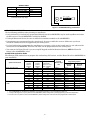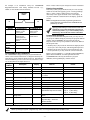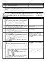
1
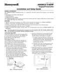
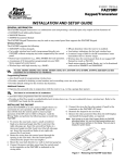
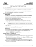
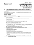
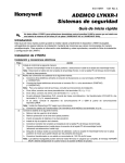
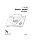
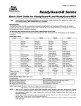
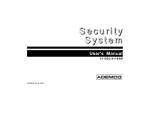
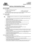
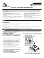
K4460-11 10/08 Rev A
6150RFAPX2
6150RFAPX2
Keypad/Transceiver
INSTALLATION AND SETUP GUIDE
GENERAL INFORMATION
The 6150RFAPX2 is a combination unit incorporating a normally-open relay output, a fixed English keypad and a transceiver.
The 6150RFAPX2 Keypad/Transceiver may be used on any control panel that supports the 6150 Keypad. The 6150RFAPX2
supports the following:
• 5828/5828V wireless keypads.
• Up to eight wireless keys locally (programmed directly into
6150RFAPX2) without occupying any zones supported by the
control panel.
• Button-type transmitters (e.g., 5804, 5804BD) for local operation.
• A maximum of 16 transmitters programmed into any 5800
Series-supported control panel.
• RF jam detection when the receiver is enabled.
UL
• Low-battery indications for the local wireless keys.
• A nominal range of 200' for the RF transmitters (some
transmitters have a shorter range).
• Wireless keys for control panels that do not support RF
themselves (such as 4110DL).
• Sends status signals (Armed, Ready, etc.) to two-way
units such as 5804BDV and 5828/5828V.
The 5802, 5802MN, 5802MN2, 5804, 5804BD, 5804BDV, 5804E, 5814, 5816TEMP, 5819, 5819BRS, 5819WHS, 5828/5828V and 5850
transmitters are not intended for UL installations.
Programming Features
• Auto Enroll mode for programming wireless keys.
• Provides a method for deleting a serial number and re-enrolling a new one in its place.
• Provides default settings for the wireless key functions.
Additional Features
• Optional back case available for use when mounting adjacent to AVST-APX Audio Verification System Remote. Order Part
# 6150APX-CASE.
• Operates the on-board relay in conjunction with the receiver (e.g., to trip a garage door opener).
UL
This feature is not intended for UL installations.
• Activates relays programmed into the control panel.
• Provides an End User mode to enable/disable local wireless keys (e.g., if a user accidentally loses a wireless key). Refer to the
6150RFAPX2 User Guide for this procedure.
Locate the 6150RFAPX2 in an area and at a height where it
is convenient for user operation. The 6150RFAPX2 must be
at least 10 feet from the control panel to ensure proper
operation of the RF receiver. Perform the following steps.
1. Push the two case release snaps at the bottom of the
keypad with the blade of a medium screwdriver (this will
push in the release snap), then pull that side of the case
back away. Insert the screwdriver in the side of the
keypad (between the front and back case) and gently
twist to release the side locking tab. Repeat for the other
side. Refer to Figure 1 for location of the case back
release snaps and locking tabs.
2. Route the wiring from the control panel through the
opening in the case back. (See the control panel’s
instructions for proper wire run lengths.)
3. Mount the case back directly to a wall or electrical gang
box.
4. Connect the power and data wires from the control panel
to the terminals on the 6150RFAPX2 as indicated in the
wiring table adjacent to Figure 2.
5. Connect the wires for the relay output (if used) to the
terminals on the 6150RFAPX2’s PC board.
Note: Upon power-up or exiting the Program Mode, the 6150RFAPX2
alternately flashes "Ad" and the 2-digit keypad address and the
2-digit receiver address on the display. Press any key to
display the system status.
6. Reattach the keypad to its case back.
ARMED
READY
WW W.APX A LARM.CO M
NOTE:
TO REMOVE CASE BACK
PUSH IN THE TWO MOUNTING
SNAPS LOCATED ALONG THE
BOTTOM OF THE KEYPAD
AND LIFT UP.
RETAINING
SNAPS
LOCKING
TAB
6150APX-001-V0
INSTALLING THE 6150RFAPX2
Figure 1 – Removing the 6150RFAPX2 Case Back
WIRING TABLE
Control Panel
Data In
− Aux Pwr (GND)
+ Aux Pwr
Data Out
Wire Color
Green
Black
Red
Yellow
Note: NO (normally Open) and C (common) are the
connections for the relay output
Y
+
Keypad
▲G
−
+
▼Y
G
NO C
6150RF-003-V2
Figure 2 - 6150RFAPX2 Wiring Connections
APPLICATION GUIDELINES
Use the following guidelines when planning an installation:
• Local wireless keys (wireless keys programmed directly into the 6150RFAPX2) may be used regardless of whether
the RF receiver in the 6150RFAPX2 is enabled or disabled.
• If using bi-directional devices, be sure to enable the transmitter module in the 6150RFAPX2.
• If transmitters are programmed into the control panel, be sure to enable the receiver. (Make sure you do not
exceed the number of receivers supported by the control panel.)
• If a local wireless key is programmed to arm/disarm or to trigger a relay on the control panel, a user code must be
entered into the 6150RFAPX2. This user code must also be programmed into the control panel.
• You must set the House ID only if you are using RF keypads and/or bi-directional devices; AND the House ID
Source is the 6150RFAPX2 (Local).
6150RFAPX2 Application Guide
The following guide outlines how to program the wireless keys, RF receiver, and the House ID in the 6150RFAPX2 for
your installation.
Are you using
Program
Wireless Keys
Into
6150RFAPX2
Programming Options
RF keys
beyond
system’s
capacity?
RF receivers
beyond
system’s
capacity?
RF keypads and/or
Bi-directional
devices on more
than 1 partition?
VISTA-10P, VISTA-15P
NO
YES
YES
NO
NO
YES
N/A
N/A
N/A
System
6150RFAPX2
6150RFAPX2
ON [1]
ON [1]
OFF [0]
System [1]
System [1]
Local [0]
VISTA-20P
NO
YES
YES
NO
YES
NO
NO
YES
YES
YES
NO
NO
NO
YES*
YES*
System
6150RFAPX2
6150RFAPX2
System
6150RFAPX2
ON [1]
ON [1]
OFF [0]
OFF [0]
OFF [0]
System [1]
System [1]
Local [0]
Local [0]
Local [0]
VISTA-40, VISTA-50P, VISTA128BP
NO
YES
YES
NO
YES
NO
NO
YES
YES
YES
NO**
NO**
NO**
YES
YES
System
6150RFAPX2
6150RFAPX2
System
6150RFAPX2
ON [1]
ON [1]
OFF [0]
OFF [0]
OFF [0]
System [1]
System [1]
Local [0]
Local [0]
Local [0]
System Control Panel
Receiver
Enable
House ID
Source***
* Two 6150RFAPX2s are needed for this application: one assigned to partition 1 and one assigned to partition 2.
** If using an RF keypad on only one partition, the 6150RFAPX2’s partition assignment in panel programming must match the partition.
*** If set for Local on a partition control, the 6150RFAPX2’s partition assignment must match the one programmed in the BD device.
-2-
shown. These values may be changed to suit the installation.
An example of an installation using two 6150RFAPX2
Keypad/Transceivers with 2-Way Wireless Devices (e.g.,
5828V) on Two Partitions is shown below:
Entering Program Mode
Press the [1] and [3] keys simultaneously for a few seconds,
within 30 seconds after applying power. The keypad beeps
three (3) times, and two dashes and two zeroes flash
alternately in the upper left-hand corner of the display. If
any other numbers or letters flash in the display, press the
[✻] key.
CONTROL
PANEL
6150RFAPX2
#1
Settings
6150RFAPX2
#2
6150RFAPX2 #1
Note: The keypad will not enter programming mode if the
system has been armed before the 6150RFAPX2 was
powered up or down.
Pressing the [1] and [3] keys 30 seconds or more after
applying power allows you to enter the User mode. This
mode allows you to enable and disable individual local
wireless keys (useful if, e.g., a user accidentally loses a
wireless key). Refer to the User Guide for instructions.
6150RFAPX2 #2
Keypad:
Must be assigned to
Partition 1 in the
control panel
Must be assigned to
Partition 2 in the
control panel
House ID:
Match Partition 1
House ID in the
control panel and
House ID in Wireless
Device
Match House ID in
Wireless Device
House ID
Source:
System
Local
Receiver
Enable:
On
Off
Transmitter
Enable:
On
On
Programming Operations
Once you have entered the Program mode, you may move to
any program address simply by entering the program address
number. The 6150RFAPX2 will automatically exit the
Program mode if no keys are pressed for 90 seconds. While in
the Program mode:
• Pressing the [✻] key stores the information displayed, then
moves you to the next prompt, and the keypad beeps twice.
• Pressing the [#] key erases the current information and
moves you back so you may enter the correct information.
PROGRAMMING THE 6150RFAPX2
Enter a program address (e.g., press [1] for Keypad Address;
[2] for Receiver Address) to set the parameters in the
6150RFAPX2.The following chart lists the program
addresses, the keypad display, and the choices.
The 6150RFAPX2 is shipped with pre-programmed default
values. Later in these instructions are diagrams showing the
wireless keys' loops and their default functions. Regardless of
which wireless key you use (even if it is one not shown), loops
1-4 are defaulted for all eight devices as
Program
Address
1
2
3
4
Keypad Address
Receiver Address
House ID
House ID Source
cA
rA
HI
hS
5
Wireless Key Editing
d-
6
7
8
8 then 2
8 then 4
Receiver Enable
Transmitter Module Enable
Wireless Key Auto Enroll
Wireless Key User Code
Wireless Key Loop Function
rE
tE
d*
u4
Ln
8 then 5
Wireless Key On-Board Relay
Assignment
Restore Defaults
o-
Description
Display
Choices
Default
01-31
00-30
01-31
1 = System
0 = Local
Enter Existing Device Number
31
00
10
1 System
1 = On 0 = Off
1 = On 0 = Off
Enter Serial Number
Enter 4-Digit User Code
Enter Loop Number then Function
(See Wireless Key Function Chart)
1 Enable
1 Enable
Enter Loop Number then Relay
Action
9
EE
1 = Restores Defaults
Any Other Key = Does Not
Restore Defaults
0
High Security Mode✝
En
1 = Enable; 0 = Disable
* The keypad will display the next number that can be enrolled (i.e., “d3”)
Loop 2
Loop 3
Loop 4
Loop 1
1 (Disarm)
2 (Arm Away)
3 (Arm Stay)
Close for 2 Seconds
0 Disable
✝ When operating the system in High-Security mode, non-encrypted wireless keys will not function.
-3-
Defaulting the 6150RFAPX2
To restore the 6150RFAPX2 to the default values, perform the following steps:
Step
Action
1
Enter the Program mode by pressing the [1] and [3] keys simultaneously for a few seconds within 30 seconds after
applying power. The keypad alternately flashes “oo” and two dashes.
2
Press the [9] key. The display flashes “EE.”
3
Press the [1] key to restore the default values, or press any other key to exit without restoring the default values.
If you pressed [1], the keypad beeps three (3) times and returns to alternately flashing “oo” and two dashes. If you
pressed any other key, the keypad will beep two (2) times, and return to alternately flashing “oo” and two dashes.
4
Press [✻] to exit the 6150RFAPX2 Program mode.
Programming Procedure
This section is divided into two parts.
•
•
Programming for an installation WITHOUT local wireless keys.
Programming for an installation WITH local wireless keys.
Using the programming procedure WITH local wireless keys, is necessary only if you plan to use wireless keys
beyond the control panel’s capacity, or on a system that does not support 5800 Series wireless. Refer to the
6150RFAPX2 Application Guidelines section for installations that require these settings.
Note: See the control panel's installation instructions for the acceptable keypad and receiver addresses.
If you are using a wireless key in High-Security mode (5804E) in the control panel, it will occupy one of the devices in the
6150RFAPX2.
Programming for an Installation WITHOUT Local Wireless Keys
To program the 6150RFAPX2 for an installation without any local wireless keys, perform the following steps:
Step
Action
Display
1.
Enter the Program mode by pressing the [1] and [3] keys
simultaneously for a few seconds within 30 seconds after applying
power or within 30 seconds after removing the case back.
Alternately flashes "oo" and two dashes.
2.
Enter [1] (Keypad Address). Enter the 2-digit keypad address (01-31).
Press the [✻] key to continue.
Alternately flashes "cA" and the 2-digit keypad
address.
3.
Enter [2] (Receiver Address). Enter the 2-digit receiver address (00-30).
Press the [✻] key to continue.
Alternately flashes “rA” and the 2-digit receiver
address.
4.
Enter [4] (House ID Source). Enter [1] (System) to use the House ID
programmed into the control panel, if RF keypad(s) and/or bidirectional device(s):
• Are used on the control panel.
OR
• Neither is used.
Enter [0] (Local) to use the House ID programmed into the
6150RFAPX2 (Program Address 3).
Note: If the House ID Source is:
• System (1), RF keypad and bi-directional units MUST match the
House ID programmed into the control panel.
• Local (0), RF keypad and bi-directional units MUST match the
House ID programmed into the 6150RFAPX2.
Press the [✻] key to continue.
Alternately flashes “hS” and either "1" or "0."
5.
Enter [6] (Receiver Enable). Enter [1] to enable, or [0] to disable.
Enable the receiver if RF transmitters or wireless keypads are
programmed into the control.
Note: Make sure the number of receivers set for Enable (1) does not
exceed the capacity of the control panel.
Press the [✻] key to continue.
Enter [7] (Transmitter Module Enable). Enter [1] to enable, or [0] to
disable. Enter [1] if bi-directional devices are being used.
Note: If the House ID Source is System and more than one 6150RFAPX2
is used, make sure each of the keypads have the Transmitter
Module enabled. See Note under House ID Source step 4.
Press the [✻] key.
Alternately flashes “rE” and either "1" or "0."
6.
-4-
Alternately flashes “tE” and either "1" or "0."
Step
Action
Display
Enter [0] (High-Security Mode). To put the system into High-Security
mode, enter [1]. Enter [0] to disable.
Press the [✻] key to exit the 6150RFAPX2 Program mode.
7.
8.
En
“READY” or “NOT READY”
Note: This is all the 6150RFAPX2 programming necessary for this application. Upon exiting the Program mode, the 6150RFAPX2
alternately flashes "Ad," the 2-digit keypad address, and the 2-digit receiver address. If either of these is incorrect, repeat steps 1
through 3.
Programming for an Installation WITH Local Wireless Keys
• The 6150RFAPX2 is supplied with default settings for the functions of the wireless keys. See page 3.
• If, during the programming of the wireless keys, you make a wrong entry and want to reprogram a wireless key, simply
press the [#] key, then enter the correct information.
Perform steps 1-6 in the Programming for an Installation Without Local Wireless Keys section. Then perform the
following steps:
Step
1.
2.
3.
4.
5.
6.
Action
Enter [3] (House ID). Enter the 2-digit House ID for the 6150RFAPX2
(01-31).
Note: The House ID is needed only if RF keypads and/or bi-directional
units are used and House ID source is set for Local.
The House ID entered here MUST match the House ID
programmed in the RF keypad and the bi-directional unit.
Press the [✻] key to continue.
Enter [8] (Wireless Key Auto Enroll). The 6150RFAPX2
automatically advances to first available device number.
Note: If all 8 devices have been enrolled, the 6150RFAPX2 beeps three
times and continues to alternately flash "oo" and "--."
Press any button on the wireless key to enroll the serial number. The
keypad will beep three times.
Note: If enrolling a wireless key (5804E) in high-security mode, press all
four buttons on the wireless key simultaneously.
Press the [✻] key to accept the serial number; OR press the [#] key to
reject the serial number.
If you accept the serial number, the 6150RFAPX2 beeps two times. If
you reject the serial number, the 6150RFAPX2 beeps once and returns
to the “enroll serial number” prompt.
Note: A maximum of 8 wireless keys may be enrolled into the
6150RFAPX2. These wireless keys DO NOT occupy any zones
supported by the control.
If you are finished programming for now, press [✻] to exit. Otherwise,
continue with step 5.
Enter [2] (User Code). Enter the 4-digit user code for the wireless
key.
Note: The user code must be a valid code that is programmed in the
control panel.
Press the [✻] key to accept the user code.
If you are finished programming for now, press [✻] to exit. Otherwise,
continue with step 6.
Enter [4] (Loop Functions). Enter the loop number (1-4).
Note: The 6150RFAPX2 is shipped with the loop functions preprogrammed. Perform steps 6 through 10 only if it is necessary to
change any of the loop functions.
Loop 1 Close the 6150RFAPX2 On-Board Relay for 2 sec.
Loop 2 1 (Disarm)
Loop 3 2 (Arm Away)
Loop 4 3 (Arm Stay)
See the Wireless Key Function Chart below for the choices.*
* Entering a number other than the one specified may give
unpredictable results
-5-
Display
Alternately flashes “hl” and a 2-digit number.
Flashes "d" with the next available device
number; followed by “- -“ (four times) and then
repeats the sequence.
Alternately flashes "d" with the device number
and the serial number.
If you accept the serial number, the display
flashes the device number and a hyphen.
If you reject the serial number, the display
flashes "d" with the device number followed by
“--” four times.
Flashes "u4." Once the 4-digit user code is
entered, the display flashes "u4," the first two
digits, and then the last two digits of the user
code.
Flashes "Ln."
Once the loop number is entered, alternately
flashes "L" with the loop number; and the present
function.
Step
6.
(Cont’d)
Action
Display
Wireless Key Function Chart
Function
Disarming
Arming Away
Arming Stay
Arming Maximum (Away Instant)
Arming Instant
Panic Alarm
Produces type of alarm [* & #]
programmed in control panel.
Default Loop Functions
Entry
1
2
3
4
7
Loop 3
Arm AWAY
Loop 2
Disarm
Loop 4
Arm STAY
Loop 1
Close on-board relay
for 2 seconds
# + 99
5804
# + 7 (VISTA-10SE, VIA-30PSE)
# + 7 + n (VISTA-10P, VISTA-15P,
VISTA-20P, VISTA-20SE(HW))
# + 8 (VISTA-10SE, VIA-30PSE)
Manually Stop a Relay Action
# + 8 + n (VISTA-10P, VISTA-15P,
VISTA-20P, VISTA-20SE(HW)
Activate Relay as Programmed in
# + 71 (VISTA-40, VISTA-50P,
Control
VISTA-128B)
Activate Relay as Programmed in
# + 72 (VISTA-40, VISTA-50P,
Control
VISTA-128B)
Activate Access Control Relay for
0 (VISTA-40, VISTA-50P, VISTAPartition
128B)
n = Device Number programmed in panel to be controlled
Loop 2
Disarm
Manually Start a Relay Action
Loop 1
Close on-board relay
for 2 seconds
••
•
••
Press the [✻] key.
Loop 4
Arm STAY
Loop 3
Arm AWAY
••
• • ••
• •• • ••
••
SET
HOUSE
CODE
5 8 0 4 B D / 5 8 0 4 B DV
NOTE: If the loop is defaulted with a function (e.g.,
Arm, Disarm) and also is assigned to activate
the on-board relay, the system performs
BOTH functions.
7.
Repeat step 6 for the rest of the loops of the wireless key.
8.
To program a button on the wireless key to control the on-board
relay, enter [5] (On-Board Relay Assignment).
Flashes "o-."
9.
Enter the loop number of the wireless key (1-4). Enter the relay
action (0 = no action; 1 = relay off; 2 = relay on; 3 = relay toggles on
and off; 4 = relay closes for 2 seconds).
Flashing “o” and the loop number.
Once the action is entered, displays “o” and
alternately flashes the loop number and the relay
action.
Note: The relay action must be "0" for UL installations.
Press the [✻] key.
10.
Repeat step 9 for the rest of the loops.
11.
When all loops have been programmed for the wireless key, press the
[✻] key.
The 6150RFAPX2 automatically displays the next available device
number (one that does not have a serial number).
If you want to program additional wireless keys, repeat steps 3
through 10. Otherwise, press the [#] key. This takes you back to the
main display, which alternately flashes “oo” and “- -.”
Enter [0] (High Security Mode). To put the system into High-Security
mode, enter [1]. Enter [0] to disable.
12.
13.
14.
Flashes “d” followed by the device number.
Flashes “En” and “0” alternately OR “En” and
“1” if the keypad is in high-security mode
Press [✻] to exit the 6150RFAPX2 Program mode.
Note: Upon exiting the Program mode, the 6150RFAPX2 alternately flashes "Ad," the 2-digit keypad address, and the 2-digit receiver
address. If either of these is incorrect, repeat steps 1 through 3 in the Programming for an Installation Without Local Wireless
Keys section.
Deleting, Replacing, or Editing Wireless Keys
Use the following procedure to delete, replace, or change any of the programming for a wireless key.
Step
Action
Display
1.
Enter the Program mode by pressing the [1] and [3] keys
simultaneously for a few seconds within 30 seconds after applying
power.
Alternately flashes "oo" and two dashes.
2.
Enter [5] (Wireless Key Editing). Enter the device number for the
wireless key you want to edit. This must be a device that has its
serial number programmed in the 6150RFAPX2 already.
To delete the serial number, press [✻], then press [9], and press [✻]
again.
To exit without deleting the serial number, press the [#] key.
Press the [✻] key to continue.
Flashes the device number and a hyphen.
-6-
Once the device number is entered, alternately
flashes "d" with the device number; and the serial
number.
Step
Action
Display
To change any of the programming for the wireless key, perform one
of the following steps in the Programming for an Installation WITH
Local Wireless Keys section.
•
For the user code, perform step 5.
•
For the loop functions, perform steps 6 and 7.
•
For the on-board relay assignment, perform steps 8 to 10.
When you have completed editing the wireless keys, press the [✻] key
4.
twice to exit the Program mode.
* The keypad will display the last number that was enrolled (i.e., “d3”)
3.
Alternately flashes "d*" with the device number;
and “--.”
Note: Upon exiting the Program mode, the 6150RFAPX2 alternately flashes "Ad," the 2-digit keypad address, and the 2-digit receiver
address. If either of these is incorrect, repeat steps 1 through 3 in the Programming for an Installation Without Local Wireless
Keys section.
TROUBLESHOOTING
The following error messages cause the 6150RFAPX2 to produce rapid beeps for 5 seconds. The table below
describes the error messages and the corrective actions.
Display
Probable Cause
Corrective Action
Lb
Low battery in a wireless key
1.
2.
OC
1C
Check 09 OR
Check 100 OR
Check 1nn *
Replace the battery in the wireless key.
Replace the transmitter if the wireless key does not have a replaceable
battery.
Verify that the Data Out wire is connected properly.
Verify that the control panel is not a First Alert-type control panel.
1. Verify that the Data In wire is connected properly.
Open circuit
Incompatible connection
1. 6150RFAPX2 Receiver is
not communicating
2. Another device on the
2. Verify the wiring connections between the control and all other devices.
keypad terminals is not
communicating to the
control panel
E8
Too many RF zones
Verify the number of transmitters programmed into the control panel
programmed
*nn = receiver address programmed in VISTA control panel
SPECIFICATIONS
Physical:
Wiring:
6-1/4” H x 4-7/8” W x 1” D
(158.75mm x 123.8mm x 25.4mm)
Refer to Wiring Table on page 2
Range:
200' nominal
Frequency:
345 MHz
Voltage:
Current:
Relay:
Sounder:
12VDC
Standby 80mA
Backlighting on and
Sounder on 105mA
Normally-Open, 1A, 28VDC
Piezo-electric (fire alarm is loud pulsing tone;
burglary/audible panic alarm is two tone
sound
FOR DETAILS ON THE LIMITATIONS OF THE ENTIRE ALARM SYSTEM, REFER TO THE INSTALLATION INSTRUCTIONS
FOR THE CONTROL PANEL WITH WHICH THIS DEVICE IS USED.
-7-
This device complies with Part 15 of the FCC rules. Operation is subject to the following two conditions: (1) This device may not cause harmful
interference, and (2) This device must accept any interference received, including interference that may cause undesired operation.
FEDERAL COMMUNICATIONS COMMISSION (FCC) Part 15 STATEMENT
This equipment has been tested to FCC requirements and has been found acceptable for use. The FCC requires the following statement for your
information:
This equipment generates and uses radio frequency energy and if not installed and used properly, that is, in strict accordance with the manufacturer's instructions, may cause interference to radio and television reception. It has been type tested and found to comply with the limits for a
Class B computing device in accordance with the specifications in Part 15 of FCC Rules, which are designed to provide reasonable protection
against such interference in a residential installation. However, there is no guarantee that interference will not occur in a particular installation. If this
equipment does cause interference to radio or television reception, which can be determined by turning the equipment off and on, the user is
encouraged to try to correct the interference by one or more of the following measures:
•
If using an indoor antenna, have a quality outdoor antenna installed.
•
Reorient the receiving antenna until interference is reduced or eliminated.
•
Move the radio or television receiver away from the receiver/control.
•
Move the antenna leads away from any wire runs to the receiver/control.
•
Plug the receiver/control into a different outlet so that it and the radio or television receiver are on different branch circuits.
If necessary, the user should consult the dealer or an experienced radio/television technician for additional suggestions. The user or installer may
find the following booklet prepared by the Federal Communications Commission helpful: "Interference Handbook"
This booklet is available from the U.S. Government Printing Office, Washington, DC 20402.
The user shall not make any changes or modifications to the equipment unless authorized by the Installation Instructions or User's Manual.
Unauthorized changes or modifications could void the user's authority to operate the equipment.
For the latest warranty information, please go to:
http://www.security.honeywell.com/hsc/resources/wa/index.html
5132 North 300 West
Provo, Utah 84604
(800) 216-5232
www.apxalarm.com
ÊK4460ÊK4460-11;Š
K4460-11 10/08 Rev A