1
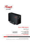
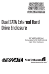
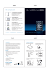
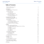
DF-7506
1-to-2 SATA II
RAID Box
User Manual
Version 1.0
DF-7506 1-to-2 SATA II RAID Box
Table of Contents
Chapter 1
1.1
Product Introduction .................................................................................3
Features.......................................................................................................................................................................3
1.1.1
Shipping Package Content.........................................................................................................................3
1.2
Front View ..................................................................................................................................................................4
1.3
Rear View....................................................................................................................................................................6
1.4
Disk Drive Installation Steps:..............................................................................................................................7
1.5
RAID Concepts .........................................................................................................................................................8
1.5.1
RAID Modes .....................................................................................................................................................9
Chapter 2
Getting Started .........................................................................................12
2.1
Preparing the Subsystem.................................................................................................................................. 12
2.2
SteelVine Manager GUI ..................................................................................................................................... 14
2.2.1
Appliance-Only Mode ............................................................................................................................... 14
2.2.2
GUI-Only Mode............................................................................................................................................ 15
2.2.3
Status-Only Mode....................................................................................................................................... 21
2
User Manual
DF-7506 1-to-2 SATA II RAID Box
Chapter 1 Product Introduction
1.1 Features
¾
1-to-2 Intelligent SATA II RAID Solution
¾
RAID Levels Supported: FAST (RAID 0), SAFE (RAID 1), JBOD, BIG, SAFE33
and SAFE50
¾
Up to SATA II 3Gbps host and device port capability
¾
Automatic Failover support in RAID 1 mode
¾
Automatic Rebuild in RAID 1 mode
¾
Easy to use automatic RAID mode configuration
¾
100GB/hr Rebuild speed without increased the host CPU load
¾
Device-to-device(s) copy during rebuild without the performance penalty on
host CPU
¾
Platform Independent: Supports virtually any platform with SATA drive port
¾
OS Independent: Support virtually any OS that supports SATA drive
¾
Simplicity: Can be directly attached to a SATA I or II host drive port
¾
Ease of Integration: Standard full-height 5.25 in. form factor
¾
Serviceability: Drive bays with hot-swap capability
¾
Cost Effectiveness: Supports two 1-inch SATA drives
¾
Indicators: LED for disk access, disk failure, over-heating and rebuild status
¾
Failure Notification: Front panel LED indicators for fan failure additionally
backed up by an audible alarm
¾
Advanced Management and configuration utilities: GUI based management
and configuration
1.1.1 Shipping Package Content
The product package contains the following items:
- One RAID Box
- One SATA female-female flat cable
- Installation Guide (CD), Screws and key set package
User Manual
3
DF-7506 1-to-2 SATA II RAID Box
1.2 Front View
LEDs Status Table
Function LED
Disk
Access
Disk
Access
Disk
Status
Disk
Status
Disk
Status
Host
Power
Host
Access
Status
Solid Red
Blinking
Red
Solid
Green
Blinking
Green
Blinking
Amber
Solid
Green
Solid Red
Disk Power On
Disk Accessing
√
√
No disk / Disk
failed
√
Disk Verifying
√
Array Rebuilding
√
√
√
√
Host Connected
Host Accessing
√
√
√
Over
Temperature
(55℃ / 131℉)
4
User Manual
√
DF-7506 1-to-2 SATA II RAID Box
Door Latch
The door latch is used to open the door to gain access to the disk slots.
Disk Slots
There are two disk slots for inserting disk drives.
RAID Mode Confirm (SW 2)
After power on, use this switch to apply the RAID Mode change.
NOTE: Whenever the RAID mode is modified (SW3 is changed) from
one mode to another, the RAID Mode Confirm must be pressed after
system power on to enable the RAID box to detect and save the new
RAID mode.
Disk Slot Lock
The Disk Slot Lock, when in locked position, will power on the disk drive in the
slot. It also serves to secure the disk drive inside the slot.
NOTE: The Disk Slot Lock must be locked in order for the RAID box to
detect the disk drive in the slot.
Mute Buzzer
Use this to silence the alarm buzzer.
User Manual
5
DF-7506 1-to-2 SATA II RAID Box
1.3 Rear View
SATA Port - The RAID box has one SATA port for connecting to Host/Server.
Switch 3 (SW3) - Use this switch dial to change the RAID Mode setting. Refer
to Section 1.5 for more information about RAID Modes. By default, the RAID
box is configured to RAID 1 (SAFE) mode.
Fan - The fan provides proper ventilation for the RAID box.
Power Input Socket - Use the Power Input Socket for connecting the power cables
in the Host/Server.
JP6 - Reserved. (Please do not remove this jumper.)
Fan Fail Alarm Disable (JP5)
JP5 SETTING
6
User Manual
1–2
OFF
2–3
ON
DF-7506 1-to-2 SATA II RAID Box
1.4 Disk Drive Installation Steps:
1. Pull out an empty disk tray (You can install in any available slot.)
2. Place the hard drive in the disk tray.
3. Install the mounting screws on each side to secure the drive in the disk tray.
4. Slide the tray into a slot until it clicks into place.
5. Lock the disk tray by using the key (included in your package) and turning it
clockwise. The RAID box, when powered on, will detect the hard disk when in
locked position. This will also lock the disk tray into the RAID box providing disk
drive security. If you are replacing a new hard drive, make sure to unlock it by
turning the key counter-clockwise
NOTE: The Disk Slot Lock must be locked in order for the RAID box to
detect the disk drive in the slot.
6. The Disk Status LED will turn green. If the Disk Status LED did not turn green,
check the hard drive if it is in good condition. When the hard drive is being
accessed, the Disk Access LED illuminates.
User Manual
7
DF-7506 1-to-2 SATA II RAID Box
1.5 RAID Concepts
The basic idea of RAID (Redundant Array of Independent Disks) is to combine multiple
inexpensive disk drives into an array of disk drives to obtain performance, capacity and
reliability that exceeds that of a single large drive. The array of drives appears to the
host computer as a single logical drive.
From (PC) host controller, each logical device (RAID volume) controlled by the RAID box
acts just the same as single regular hard disk although a RAID volume generally consists
of more than one hard disk drives.
The RAID box provides several RAID Modes as described below.
SW3
RAID Mode
0
BIG
1
JBOD
2
RAID 0
3
RAID 1
4
SAFE 33
5
SAFE 50
6
Reserved
7
GUI Only
8
Reserved
9
Reserved
NOTE: By default, the RAID box operation mode is RAID 1 (SW3 is set
to 3).
NOTE: In GUI Only Mode, the RAID Mode is configured only in the
SteelVine Manager GUI.
8
User Manual
DF-7506 1-to-2 SATA II RAID Box
1.5.1 RAID Modes
BIG (Concatenating)
This mode concatenates the physical hard drives as a single large volume with larger
capacity. In this mode, the capacity of Disk 0 and Disk 1 are concatenated as a single
virtual volume.
If any one hard disk gets defective, information stored in this RAID Mode will become
invalid.
JBOD (Just a Bunch of Disks)
This mode enables each hard drive to be seen separately as individual drive. When using
a SATA host controller, JBOD should only be used if the SATA host controller provides
Port Multiplier (PM) support. If a host is not PM-aware, only a single drive is presented
(Disk 0).
If any one hard disk gets defective, information stored in this RAID Mode will become
invalid.
RAID 0 (FAST)
RAID 0 (also called Striping) is the segmentation of logically
sequential data, such as a single file, so that segment can
be assigned to multiple hard disks in a round-robin fashion
and thus written concurrently.
Advantage of RAID 0 is to achieve high performance by
accumulating each individual hard disk performance.
However, if any one hard disk gets defective, information
stored in this RAID Mode will become invalid.
The RAID subsystem will just make use of the same disk
space for each hard disk under RAID 0 condition. For
example, if a RAID 0 logical volume consists of 2 different
size hard disks, the total usable space of this RAID 0
volume will be capacity of smallest size hard disk times 2.
User Manual
9
DF-7506 1-to-2 SATA II RAID Box
RAID 1 (SAFE)
RAID 1 (also called Mirroring) is the replication of data onto
the other hard disk in real time to ensure continuous data
availability. In a RAID 1 system with two hard disks, the
data in one hard disk will be exactly the same as the data in
the other hard disk.
The capacity of the RAID 1 volume will be equivalent to the
size of one drive (if both drives are the same) or the smaller
of the two drives (if they are different).
RAID 1 provides that highest level of data protection. Failure
in one hard disk will cause the RAID 1 volume to enter into
degraded mode. The host controller can still read/write data
to the volume without knowing any hard disk failure. When
the failed hard disk is replaced, an on-line rebuild will be
started automatically to restore data redundancy.
Although the volume remains accessible during rebuild process, the volume is
susceptible to data loss through damage to the remaining drive until redundancy is
restored at the end of the rebuild and verification process. Host access takes precedence
over the rebuild process. If the volume is continually used during the rebuild, the rebuild
process will take a longer time to complete, and the host data transfer performance will
also be affected.
SAFE 33
The SAFE33 RAID mode creates two virtual volumes; one SAFE (RAID 1) volume and
one BIG volume, and should be used when you need the high reliability for some of your
data (with the added overhead of mirroring) but you don’t need high reliability for the
remainder of your data. SAFE33 reduces the cost of additional hard drives in operations
where non-critical data could be lost without severe consequences.
SAFE33 uses a SAFE volume that is mirrored across two hard drives to protect your
critical data in the event a hard drive failure. If one drive fails the SAFE volume is
retrievable although the BIG volume is not. When you replace the failed drive, the SAFE
volume is automatically rebuilt on to the replacement drive.
For example, if you are using a video editing application that stores the primary source
data and also uses some temporary storage for editing, you need protected storage that
is offered by SAFE for the primary source data, but you do not need protected storage
for the temporary data. Therefore, the combination of SAFE and BIG would be the most
efficient utilization of your available storage capacity. If either hard drive fails the
primary data stored on the SAFE volume would still be available whereas the temporary
data stored on the BIG volume would be lost.
10
User Manual
DF-7506 1-to-2 SATA II RAID Box
The size of the SAFE volume of a SAFE33 RAID mode will be one-third of the size of one
hard drive (if they are equal) or one-third of the size of the smaller (if they are not
equal.) The size of the BIG volume will be the combination of all remaining capacities.
For example: if there are two 300GB hard drives used in SAFE33 RAID mode, the
capacity of the SAFE volume will be 100GB (1/3 of 300GB) and the BIG volume will be
400GB (the remaining capacity after allocating 100GB from each hard drive).
A SATA host connection must have a PM (Port Multiplier) aware host adapter when using
SAFE33 so that the two volumes can be detected by the host. If your SATA host adaptor
is not PM aware, then ONLY the SAFE volume will be detected and the BIG volume will
not be accessible.
SAFE 50
The SAFE50 RAID mode creates two virtual volumes; one SAFE (RAID 1) volume and
one BIG volume, and should be used when you need the high reliability for some of your
data (with the added overhead of mirroring) but you don’t need high reliability for the
remainder of your data. SAFE50 reduces the cost of additional hard drives in operations
where non-critical data could be lost without severe consequences.
SAFE50 uses a SAFE volume that is mirrored across two hard drives to protect your
critical data in the event a hard drive failure. If one drive fails the SAFE volume is
retrievable although the BIG volume is not. When you replace the failed drive, the SAFE
volume is automatically rebuilt on to the replacement drive.
For example, if you are using a video editing application that stores the primary source
data and also uses some temporary storage for editing, you need protected storage that
is offered by SAFE for the primary source data, but you do not need protected storage
for the temporary data. Therefore, the combination of SAFE and BIG would be the most
efficient utilization of your available storage capacity. If either hard drive fails the
primary data stored on the SAFE volume would still be available whereas the temporary
data stored on the BIG volume would be lost.
The size of the SAFE volume of a SAFE50 RAID mode will be one-half of the size of one
hard drive (if they are equal) or one-half of the size of the smaller (if they are not equal).
The size of the BIG volume will be the combination of all remaining capacities.
For example: if there are two 300GB hard drives used in SAFE50 RAID mode, the
capacity of the SAFE volume will be 150GB (1/2 of 300GB) and the BIG volume will be
300GB (the remaining capacity after allocating 150GB from each hard drive).
A SATA host connection must have a PM (Port Multiplier) aware host adapter when using
SAFE50 so that the two volumes can be detected by the host. If your SATA host adaptor
is not PM aware, then ONLY the SAFE volume will be detected and the BIG volume will
not be accessible.
User Manual
11
DF-7506 1-to-2 SATA II RAID Box
Chapter 2 Getting Started
2.1 Preparing the Subsystem
1. The default operation mode of the RAID box is RAID 1. If you need to modify the
RAID mode, adjust Switch 3 (SW3) on the rear panel.
SW3
RAID Mode
0
BIG
1
JBOD
2
RAID 0
3
RAID 1
4
SAFE 33
5
SAFE 50
6
Reserved
7
GUI Only
8
Reserved
9
Reserved
NOTE: In GUI Only mode, the RAID Mode is configured only in the
SteelVine Manager GUI.
NOTE: Please make sure your SATA host controller supports Port
Multiplier (PM) before setting the JBOD/SAFE33/SAFE50 mode.
2. Power off the computer and disconnect power cable(s) from source. Install the
RAID box and make sure you have the correct fitting kit for your computer, if
necessary.
12
User Manual
DF-7506 1-to-2 SATA II RAID Box
3. Connect the power cables from power supply to the Power Input Socket.
4. Connect the SATA cable to the SATA port (the other end is connected to the SATA
host controller).
5. Re-connect the power cable(s) of computer to the power source.
6. Install the disk trays with disk drives, if not yet installed.
NOTE: The Disk Slot Lock must be locked in order for the RAID box to
detect the disk drives in the slots.
7. Power on the computer. Press the “RAID Mode Confirm (pin tip)”, which is
marked SW2, with a pin tip during system boot up (to let the RAID box detect
and save new RAID mode).
NOTE: Whenever the RAID mode is changed from one mode to
another, the RAID Mode Confirm must be pressed after system power
on to enable the RAID box to detect and save the new RAID mode.
WARNING: When one disk drive fails, always use a new disk drive as
replacement. Do not use another disk drive from another RAID box as
replacement.
User Manual
13
DF-7506 1-to-2 SATA II RAID Box
2.2 SteelVine Manager GUI
NOTE: The SteelVine Manager GUI requires Microsoft .NET Framework,
which can be downloaded from
http://www.microsoft.com/downloads/details.aspx?FamilyID=0856E
ACB-4362-4B0D-8EDD-AAB15C5E04F5&displaylang=en.
The SteelVine Manager GUI installer is included in the CD that comes
with the RAID box. Install the .NET Framework first then install the
Manager GUI.
The GUI has three modes of operation:
a. Appliance-Only Mode
b. GUI-Only Mode
c. Status-Only Mode
2.2.1 Appliance-Only Mode
This mode allows you to use the RAID box with the device’s LEDs to indicate status,
without using the SteelVine Manager GUI software. To select a RAID mode in this mode
the first time that a new factory-shipped product is used, ensure that the hard disk
drives are installed, set the rotary switch on the back of the RAID box to the desired
RAID mode (not the GUI Only selection) and turn on the power. To change the RAID
mode thereafter, set the rotary switch (SW3) to the desired position and press the RAID
Mode Confirm (SW2) with a pin tip to create the new virtual volume(s). Creating new
virtual volumes will destroy any existing data that existed on the previous volume.
NOTE: By default, the RAID box operation mode is RAID 1 (SW3 is set to 3).
14
User Manual
DF-7506 1-to-2 SATA II RAID Box
2.2.2 GUI-Only Mode
This mode allows you to use the SteelVine Manager GUI to configure the RAID mode and
other settings as well as monitor the status of the RAID box (i.e. storage capacity,
volume status, and RAID mode of the desired hard drive). To select this mode the first
time that the product is used, ensure that the hard disk drives are installed, set the
rotary switch (SW3) on the back of the RAID box to the GUI-Only position and turn on
the power. In this mode, no virtual volume(s) will be created until the RAID mode and
volume selections are made through the GUI. To change from GUI mode to some other
fixed RAID mode thereafter, set the rotary switch (SW3) to the desired position and
press the RAID Mode Confirm (SW2) with pin tip to create the new virtual volume(s).
Configuration in GUI-Only Mode
To use the SteelVine Manager GUI in MS Windows OS:
1. To start the SteelVine Manager GUI, select Start Æ Program Files Æ Silicon Image
Æ 57XX SteelVine Æ SteelVineManager. Once started, the SteelVine Manager
Application icon can be found in the Notification Tray located at the bottom right
hand corner of the screen. Double click the notification tray icon to open the
SteelVine Manager GUI status window. The SteelVine Manager icon remains
active in the notification tray even if you close the SteelVine Manager window. It
can be closed by right-clicking on the icon and selecting “Exit”.
The SteelVine Manager GUI
User Manual
15
DF-7506 1-to-2 SATA II RAID Box
Menu Options available in the SteelVine Manager GUI
File Menu:
File Menu Items
Description
Change Password
Opens a dialog to establish a new password.
Scan Devices
Refreshes the status details presented on the
Status window.
Change Connections
Opens a dialog to make remote connections.
Quit
Exits the SteelVine Manager GUI (Windows
systems only)
Edit Menu:
Edit Menu Items
Description
Configure Box
Opens the “Basic Configuration Wizard”.
Schedule Disk Verify
Schedule a disk Verify activity (enabled only in
SAFE, SAFE33 or SAFE50 modes)
Configure Pop-Ups
Configure the Pop-Up messages.
Specify Policy
Display the Rebuild policy settings (enabled only in
SAFE, SAFE33 or SAFE50 modes)
Setup Email
Notification
Opens the “Setting-up Email Notification” dialog.
Event Log
Opens the “Event Log” viewer.
Specify Firmware
Opens the “Firmware Selection” dialog.
Backup Button
Open the “Accessing the Backup Button Dialog”
dialog.
Action Menu:
Action Menu Item
Description
Start Rebuild
Initiates a Rebuild to the target drive
Start Verify
Initiates a Verify activity on the selected drive
Abort Rebuild
Abort the rebuild process (only selectable when a
Rebuild operation is active)
Abort Verify
Abort the Verify process (only selectable when a
Verify operation is active)
NOTE: These Action Menu items are available only when a RAID 1
(SAFE) volume is configured.
16
User Manual
DF-7506 1-to-2 SATA II RAID Box
Toolbar Buttons:
Button
Description
Configure Box
Opens the Basic Configuration Wizard.
(appears only when using GUI
Configuration mode)
Schedule Drive
Verify
Schedule a disk Verify activity. (appears
only when SAFE volume exists)
Configure Pop-Ups
Configure the Pop-Up messages.
Specify Policy
Information
Shows the Rebuild Policy settings (appears
only when SAFE volume exists)
Specify Email
Notification
Configure the operation of email message
notification.
Event Log
View the Event Log.
Specify Firmware
View the current version or download an
updated version of the SteelVine Storage
Processor firmware.
Backup Button
Configure the third party backup application
that should be launched when the Backup
Button is pressed on the SteelVine Storage
RAID box.
2. Select a desired menu option. When prompted, enter the administrative password
(default password is admin).
User Manual
17
DF-7506 1-to-2 SATA II RAID Box
The Configure Box
To use the Configure Box to change the RAID Mode setting and create volume:
1. Select Configure Box from Edit menu or click the Configure Box from Toolbar. The
Basic Configuration Wizard will be displayed.
2. When prompted, enter the administrator password (default password is admin).
3. Select a Storage Policy.
18
Policy
Description
JBOD
Creates a logical volume for each physical
hard drive. Available only for SATA host
controllers that provide Port Multiplier
support, and only available for the top-level
node of a cascaded configuration.
SAFE (RAID 1)
Creates one volume. One hard drive mirrors
the other. The system automatically restores
data redundancy to a SAFE volume when an
offline drive comes back online.
BIG
Concatenates all hard drives into a single
volume.
SAFE33
Creates one SAFE volume that has one-third
of the available storage capacity of the
smaller hard drive and one BIG volume that
has the remaining capacity.
SAFE50
Creates one SAFE volume that has one-half of
the available storage capacity of the smaller
hard drive and one BIG volume that has the
remaining capacity.
FAST (RAID 0)
Creates one volume that is striped across two
hard drives to expose double the capacity of
the smaller drive.
User Manual
DF-7506 1-to-2 SATA II RAID Box
4. When prompted to acknowledge that the configuration change may result in data
loss, click “Yes” to accept the configuration. This clears the previously configured
RAID mode and deletes the Volume(s).
5. Select Save to Config File from the File menu to save the configuration.
6. Click Apply to create the selected configuration. Close the Wizard, and display the
volume(s) in the Status Window. (It may take up to one minute to display.)
NOTE: When SAFE (RAID 1) RAID mode is configured, the RAID 1
Volume will undergo Rebuilding and Verification process (initializing
the Volume). The RAID 1 Volume is already accessible while
initializing.
NOTE: When SAFE33 and SAFE50 RAID mode is configured, the RAID
1 Volume will also initialize.
User Manual
19
DF-7506 1-to-2 SATA II RAID Box
RAID box in SAFE (RAID 1) mode during initialization:
RAID box in SAFE (RAID 1) mode after initialization:
7. Create partition on the volume(s). Open Computer Management Console and use
Disk Management. You may also need to check if the logical device exists in
Device Manager Æ Disk Drives.
WARNING: When one disk drive fails, always use a new disk drive as
replacement. Do not use another disk drive from another RAID box as
replacement.
20
User Manual
DF-7506 1-to-2 SATA II RAID Box
2.2.3 Status-Only Mode
The Status Only Mode is entered when the rotary switch (SW3) is in the JBOD, BIG,
RAID 0 (FAST), RAID 1 (SAFE), SAFE33, or SAFE50 RAID mode.
This mode allows you to use the SteelVine Manager GUI to monitor the status of the
RAID box (i.e. volume capacity, volume status, and RAID mode), but not to change the
RAID mode configuration through the GUI. To select a RAID mode in Status Only Mode,
the first time that the product is used, ensure that the hard disk drives are installed, set
the rotary switch (SW3) on the back to the desired RAID Mode (not the GUI selection)
and turn on the power. To change the RAID Mode thereafter, set the rotary switch to the
desired position and press the RAID Mode Confirm (SW2) with a pin tip to create the
new virtual volume(s). Note that creating new virtual volumes will destroy any existing
data that existed on the previous volume.
NOTE: In Status Only mode, the “Configure Box” menu item is not
visible.
RAID box in SAFE (RAID 1) before initialization:
User Manual
21
DF-7506 1-to-2 SATA II RAID Box
RAID box in SAFE (RAID 1) after initialization:
WARNING: When one disk drive fails, always use a new disk drive as
replacement. Do not use another disk drive from another RAID box as
replacement.
22
User Manual