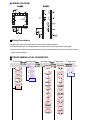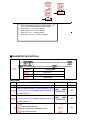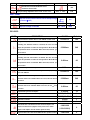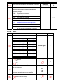
1
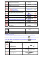
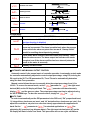
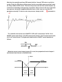
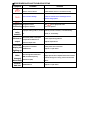
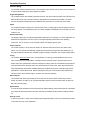
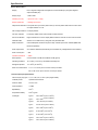
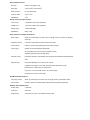
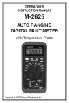
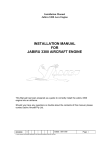
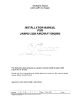
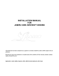
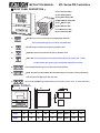
VFL Series PID Controllers
INSTRUCTION MANUAL
■FRONT PANEL DESCRIPTION:
(1) PV-Process Value
(2) SV-Setting Value
(3) AT-Auto tuning LED
(4) MA-Manual mode LED
(5) A1-Alarm 1 LED
(6) A2-Alarm 2 LED
(7) C1-Control 1 LED
(8) C2-Control 2 LED
-SET KEY. Press once to access the next programmable parameter.
(1)
Press and hold this key for 5 seconds to reset alarm timer.
(2)
-UP KEY. Press to increase the set point or parameter value.
(3)
-DOWN KEY. Press to decrease the set point or parameter value.
(4)
-SHIFT KEY. Press the shift key for 5 seconds to execute Auto Tune process (Yes. 1 mode)
To abort an Auto Tune process, press and hold the shift key for 5 seconds.
(5)
-Press the SET and UP keys once to return the normal operation.
(6)
-LEVEL KEY. Press the SET & SHIFT keys simultaneously for 5 seconds to select programming
level, then press the SET key to enter this level.
---Press the UP & DOWN keys simultaneously for 5 seconds to access “LnLo” & “LnHi” parameters.
(7)
■PANEL CUTOUT:
Model
A
B
C
D
E
a
b
c
d
48VFL
48
48
6
100
45
45+0.5
45+0.5
60
48
96VFL
96
96
10
80
91
92+0.5
92+0.5
120
96
(Units: mm)
■ WIRING DIAGRAM
■Wiring Precautions:
1. Before wiring, verify the controller label for correct model number and options.
2. For thermocouple input, use the appropriate compensation wire. And note the polarity of input signal.
3. To avoid noise induction, keep input signal wires away from instrument power lines, load lines and power lines of
other electrical equipment.
■ PROGRAMMING LEVEL PARAMETERS
■
lst. Prog. Level
2nd. Prog. Level
3rd. Prog. Level
4th Prog. Level
5th. Prog. Level
+
1. When 2nd Output (Cooling) is not selected, CPb、Cti、
Ctd、HYS2 and db parameters are not available.
2. When Pb≠0.0, HYS1 will be skipped.
3. When CPb≠0.0,HYS2 will be skipped.
4. When Pb=0.0,ti、td will be skipped.
5. When CPb=0.0,Cti、Ctd will be skipped.
■PARAMETER DESCRIPTION:
LEVEL Selection
Press
keys for at least 5 seconds to access Soft Level. Use
key to select programming level. Then press
LEVEL
or
key to enter this level.
Description
SoFt Level
PID Level
Option Level
USER LEVEL
CODE
DESCRIPTION
Set point value of control
Alarm 1 set point value/Timer set value while A1FU is set to
T.on or T. off, the unit can be HH.MM or MM.SS. It depends on
RANGE
LoLt - HiLt
Default
500
-1999 - 9999/
00.00~99.59
10
-1999 - 9999/
00.00~99.59
10
the “P.tnE” parameter.
Alarm 2 set point value/ Timer set value while A2FU is set to
T.on or T. off, the unit can be HH.MM or MM.SS. It depends on
the “P.tnE” parameter.
:Auto-tuning is disable
:Standard type auto-tuning.
Autotune PV is compared wit SV during auto tuning.
:Low PV type auto-tuning.
no
PV is compared with SV-10%FS during Auto-tuning.
:Disable the manual mode Manual control
no
:Enable the manual mode.
Output percentage. Adjustable when “Hand” is set to “Yes”
-100.0
-
0.0
100.0
SOFT LEVEL
Code
Description
Ramp rate for the process value to limit an abrupt Change
of process (℃/min)
Set point value of soft-start
Output percentage of soft-start
Range
0 - 9999
(0.0 –
999.9)
Default
0.0
LoLt - HiLt
0
0.0 - 100.0
100.0
PID LEVEL
CODE
DESCRIPTION
RANGE
Default
0.0-300.0%
10.0
0-3600sec
240
0-900sec
60
0-100sec
15
0.0-300.0%
10.0
0-3600sec
240
0-900sec
60
0-100sec
15
Hysteresis for ON/OFF control on output 1
0-2000(0.0-200.0)
1
Hysteresis for ON/OFF control on output 2
0-2000(0.0-200.0)
1
Hysteresis of alarm 1
0-2000
1
Hysteresis of alarm 2
0-2000
1
Proportional band variable. Set to 0.0 for ON/OFF control mode
Integral time (Reset). This value is automatically calculated by
activating the Autotune function. If desired, the user can later
adjust this parameter to better suit the application. When PB=0.0,
this parameter will be not available. When set to zero, Pb & td ≠ 0
for PD control
Derivative (Rate). This value is automatically calculated by
activating the Auto tune function. If desired, the user can later
adjust this parameter to better suit the application. When PB=0.0,
this parameter will be not available. When set to zero, Pb & td ≠ 0
for PI control
Proportional cycle time of output 1
Proportional band variable for secondary control output (cooling).
Set 0.0 for ON/OFF
Integral time for secondary control output. When PB=0.0, this
parameter will be not available. When set to zero, Pb & td ≠ 0 for
PD control
Derivative time for secondary control output. When Pb=0.0, this
parameter will be not available. When set to zero, Pb & ti ≠ 0 for
PI control
Proportional cycle time of output 2
Dead band value. This defines the area in which output 1 and
output 2 are both active (negative value) or the area in which
output 1 and output 2 are both inactive (positive value)
Set point offset. This value will be added to SV to perform control.
-1000-1000
(-100.0-100.0)
-1000-1000
0
0
(-100.0-100.0)
It mainly used to eliminate offset error during Pb control
-1000-2000
Process value offset. Permits the user to offset the PV indication
0
(-100.0-200.0)
from the actual PV
Parameter lock. This security feature locks out selected levels or
single parameters prohibiting tampering and inadvertent
programming changes
0000
All parameters are locked out
0001
Only SP is adjustable
0010
Only USER level is adjustable
0011
USER and PID levels are adjustable
0100
USER,PID,OPTI levels are adjustable
0101
USER, SOFT, PID, OPTI levels are adjustable
0100
0101~0111 All parameters in all levels are unlocked
1000=0000,1001=0001,1010=0010,1011=0011,1100=0100
1000~1111
The only difference is that Output 2 is unlocked
OPTION
LEVEL
CODE
DESCRIPTION
RANGE
Default
Refer to figure.
K
Input type selection.
tYPE
J
K
T
E
B
R
S
N
C
D-PT
J-PT
LINE
RANGE(℃)
RANGE(℉)
-50 ~ 1000
-58 ~ 1832
-50 ~ 1370
-58 ~ 2498
-270 ~ 400
-454 ~ 752
-50 ~ 750
-58 ~ 1382
0 ~ 1800
32 ~ 3272
0 ~ 1750
32 ~ 3182
0 ~ 1750
32 ~ 3182
-50 ~ 1300
-58 ~ 2372
-50 ~ 1800
-58 ~ 3272
-200 ~ 850
-328 ~ 1652
-200 ~ 650
-328 ~ 1202
-1999 ~ 9999
Unit of process value
:Degrees C
℃
:Degrees F
: Engineer units for linear input
Decimal point selection
0000
0000:No decimal point
000.0
000.0:0.1 resolution
0000
00.00
00.00:0.01 resolution, used for linear input only
0.000
0.000:0.001 resolution, used for linear input only
Output 1 control action.
: Reverse action for heating
: Direct action for cooling
Low limit of span or range. Set the low limit lower than the
Full range
0
Full range
1000
0.0-99.9
10.0
00.00~99.59
00.00
lowest expected SV and PV display
High limit of span or range. Set the high limit higher than
highest expected SV and PV display
Software filter.
Time scale for timer alarm.
Hours:Minutes;
Minutes:Seconds
None, Hi, Lo,
dif.H, dif.L, bd.Hi ,
bd.Lo
If A1FU=None, the alarm function is cancelled
t.on, t.oFF
none, Stdy,
Alarm 1 mode. Refer to alarm mode section for detail..
Lath, St.La
Alarm 2 function. Refer to alarm function section for detail none, Hi, Lo, dif.H,
dif.L, bd.Hi, bd.Lo
If A2FU=None, it means alarm fuction is cancelled.
t.on, t.oFF
none,
Stdy,
Alarm 2 mode. Refer to alarm mode section for details
Lath, St.La
Alarm 1 function. Refer to alarm section for details
Controller address. For use with PC RS-485 interface
0 - 255
0
Baud rate. 2.4k=2400bps, 4.8k=4800 bps, 9.6k=9600 bps,
2.4k, 4.8k
19.2k=19200 bps
9.6k, 19.2k
9.6k
Description
Default
Code
Range
Low Scale of Linear Input
-1999~9999(-199.9~999.9)
0.0
High Scale of Linear Input
-1999~9999(-199.9~999.9)
100.0
Scaling for Linear Input
1. Press and hold the UP and DOWN keys simultaneously for 5 seconds to access the “LnLo” parameter.
2. Adjust “LnLo” setting to correspond to the low scale; after adjustment, press
key once to access “LnHi”
3. Adjust “LnHi” setting to correspond to the high scale; after adjustment press
key once to exit
ALARM FUNCTION
A1FU/A2FU
ALARM TYPE
Alarm function OFF
ALARM OUTPUT OPERATION
Output OFF
Process high alarm
▲
SP
PV
Process low alarm
▲
SP
PV
Deviation high alarm
▲
SP+ALSP
PV
Deviation low alarm
▲
SP+ALSP
Band high alarm
▲
SP-ALSP
OFF
▲
SP-ALSP
Band low alarm
PV
OFF
▲
▲
PV
SP SP+ALSP
OFF
▲
▲
PV
SP SP+ALSP
On-timer
ALSP
▲
▲
SP
Off-timer
ALSP
▲
▲
SP
PV
PV
ALARM MODE
A1MD/A2MD
DESCRIPTION
Normal alarm mode/ When timer function is selected, with the PV<SV,
the timer function is disabled
Standby mode When selected, in any alarm function, an alarm on
power-up is prevented. The alarm is enabled only when the process
value reaches the alarm set point. Also known as “Startup inhibit”
(useful for avoiding alarm trips during startup)
Latch mode. When selected, the alarm output and indicator “latch”
when the alarm occurs. The alarm output and indicator will remain
energized even if the alarm condition has been cleared (unless the
power to the meter is removed)
Standby and latch mode
■AUTOMATIC AND MANUAL OUTPUT CONTROL
Automatic control is the normal mode of controller operation. In automatic control mode
the controller automatically adjusts the control output percentage, using PID, to bring the
PV equal to the SV. The PID parameters Pb, Ti and Td can be automatically determine
using the Auto Tune procedure.
Manual control allows the user to manually drive the output percentage from 0.0 to
”parameter to “
”, the right-most
100.0%. To access the manual mode, set the “
decimal (MA) on the SV display will flash. The “
” parameter will then alternately
display
and the process value. The output percentage can then be adjusted using
” to “
”.
the UP or DOWN keys. To abort the manual control, simply set “
■AUTO TUNE
In order to automatically set the PID parameters in the PID level (“Pb” proportional band,
“ti: integral time, also known as ‘reset’, and “td” derivative time, also known as ‘rate’), first
adjust the controller’s set point to a value that closely approximates the application at
” parameter to “
” for standard applications or “
” for
hand. Set the “
minimizing SV overshoot (see diagram below). The right-most decimal point (AT) on the
PV display will flash in Auto Tune mode. This procedure will run two cycle oscillations.
After that, the controller performs PID control with the “learned” PID value to verify the
results. Finally the PID values will be entered into the nonvolatile memory and then starts
the Fuzzy enhanced PID control. The auto tune process can last from several minutes up
to two hours, depending on the process in question. A time out error will occur if the auto
tune process can not be completed within two hours, in this case, try to set the PID
parameters manually. To abort an auto tune process, simply set the “
” parameter to
”.
“
The controller can also be set to ON/OFF, PI, PD and P control mode. Set Pb = 0 for
ON/OFF control mode. Set ti = 0 for PD control mode. Set td = 0 fro PI control mode and ti,
td = 0 fro P control mode. The Hysteresis (dead band) for ON/OFF control operates as
follows:
ON
OFF
SP-HYST
▲
SP+HYST
SP
When the second control output (output 2) is used, the proportional band of output 2
and the dead band interact as detailed below:
Output
Heating
Cooling
PV
Overlap
Dead
Band
Band
■ERROR MESSAGE AND TROUBLESHOOTING
Symptom
Probable
Solution
- Sensor break error
- Replace sensor
- Sensor not connected
- Check that the sensor is connected correctly
- Unit must be repaired or replaced
- A/D converter damage
- Check for outside source of damage such as
transient voltage spikes
- Auto tune time out error
Set Pb, ti, td manually
Keypad not
- Keypad is locked
- Set”
functioning
- Keypad is defective
- Have unit repaired
Process
value
unstable
No heat or
output
LEDs and
display not
lighting up
Process
Value
changed
abnormally
Entered
data lost
”to an appropriate value
- Improper setting of Pb, Ti, Td and - Start AT process to set Pb, Ti, Td automatically
CT
- Set Pb, Ti, Td manually
- No heater power or fuse open
- Check output wiring and fuse
- Output device defective or
- Replace output device
incorrect output used
- No power to controller
- Check power lines connection
- SMPS failure
- Replace or repair meter
- Suppress arcing contacts in system to eliminate high
- Electromagnetic Interference
voltage spike sources. Separate the sensors and the
(EMI) or Radio Frequency
controller wiring from “noisy” power lines. Ground
Interference (RFI)
heaters
- EEPROM error
- Replace or repair meter
Controller Overview
Controller Wiring
The controller must be wired before use. The controller’s input, outputs, and AC power are connected via
its rear terminals. Refer to the wiring diagram for details.
Programming Menus
The controller uses a menu-based programming format. The menu levels are USER, PID, OPTION, and
SOFT-START. Each menu includes a series of parameters that customize the controller. The menu
structure and parameter descriptions are detailed in the instructions on reverse side of this sheet.
Inputs
The controller accepts an input from a Thermocouple, RTD, or Analog signal. Wire the input as shown in
the wiring diagram. The measurement (PV for Process Variable) is displayed on the controller’s top LED
readout in red.
Setpoint Value (SV)
The Setpoint Value (SV) is the process application target value. For example, in an oven application the
desired oven temperature is the SV. This SV is changed adjusted as described in the operating
instructions. The SV is shown on the controller’s lower LED display digits in green.
Control Outputs
The control outputs (C1 & C2) are to be wired to an external control device such as a heater, valve,
switch, etc. The controller automatically adjusts external devices to bring the Process Variable (PV) in
line with the Setpoint Variable (SV). Available outputs are Relay, Pulsed DC, and 4-20mA Analog Output.
Tuning
The controller must be tuned for every new application. It is strongly recommended that user run the
Auto Tune function (AT). Note that the controller must be wired and ready to go before Auto Tune is
started. Auto Tune optimizes the controller’s response to exactly match the characteristics and dynamics
of the process at hand. Although auto tuning will be sufficient in most cases, there may be times when
manual adjustments are required. Qualified personnel can Manually Tune the controller using the PID
parameters in the PID Menu Level. Note that improper tuning can cause sever process disturbances;
Use Auto Tuning when possible. Again, use Auto Tune whenever possible.
Alarm Outputs
The controller has alarm output relays (A1 & A2) that can be used to switch on/off a lamp, sound a
buzzer, shut down a heater, etc. at a programmed alarm setpoint. Refer to the discussion of Alarms on
the main instruction page.
System Reset
To revert all of the parameters to their original factory default settings, press and hold the UP and DOWN
arrow keys simultaneously while turning the controller ON. Release the keys after the display switches
on.
Security LOCK
To lock the controller, in order to avoid setpoint and program tampering, refer to the information provided
in this manual for the ‘LOCK’ parameter.
Specifications
General Specifications
Display
Dual 7-segment 4-digit LED: Red digits for Process Variable (PV) and green digits for
Setpoint Variable (SV)
Display range
-1999 to 9999
Indicating accuracy
± (0.2% full scale + 1 digit)
Display update rate
4 readings per second
Output status indication Front panel Alarm (A1 and A2) and Control (C1 and C2) status LED’s inform the user when
an output switches on or off.
Out-of-range indication PV display flashes.
‘No input’ indication
PV displays ‘OPEN’ when input terminals are disconnected.
Auto Tune indication
Right-most decimal on the PV display flashes while the controller is in the auto tune mode.
Calibration data
Stored in non-volatile memory along with user parameter edits.
Meter construction
Case is ABS plastic and the front panel is drip- and dust-proof Lexan material (NEMA and
IEC IP55 equivalent)
Power requirement
90 to 264VAC 50/60Hz (automatically accommodates any voltage between 90 to 264VAC)
Power consumption
< 5VA
Insulation Resistance
> 50MΩ
Noise rejection
Common Mode: 120 dB; Normal Mode: 60 dB (typical)
Operating conditions
14 to 122 F (-10 to 50 C); 90% Relative Humidity max.
Storage temperature
-4 to 140 F (-20 to 60 C)
o
Panel cut-out dimensions
o
o
o
1.77 x 1.77" ±0.02" (45.0 x 45.0mm ±0.5mm) for 48VFL
3.62 x 3.62" ±0.02" (92.0 x 92.0mm ±0.5mm) for 96VFL
Thermocouple Input Specifications
Thermocouple (TC) types
J, K, T, E, B, R, S, N, and C (user programmable)
TC Break protect
Upscale and Downscale
Lead wire effect
0.015% / ohm
Input impedance
> 10MΩ
Repeatability
0.83 C
Temperature stability
5uV/ C typical
TC Ranges
Type K:
-58 to 2498oF (-50 to 1370oC)
Type J:
-58 to 1830 F (-50 to 1000 C)
Type B:
32 to 3272 F (0 to 1800 C)
Type T:
-454 to 752oF (-270 to 400oC)
Type E:
-58 to 1382oF (-50 to 750oC)
Type R:
32 to 3182 F (0 to 1750 C)
Type S:
32 to 3182 F (0 to 1750 C)
Type N:
-58 to 2372oF (-50 to 1300oC)
Type C:
-58 to 3272 F (-50 to 1800 C)
o
o
o
o
o
o
o
o
o
o
o
o
RTD Input Specifications
RTD type
Platinum 100Ω (DIN or JIS)
RTD range
-328 to 1202oF (-200 to 650oC)
Break protection
Up- and down-scale
Lead wire effect
0.015 / Ohm
Repeatability
0.2oC
o
Analog (Linear) Input Specifications
Current Input
4 to 20mA DC (2.7Ω input impedance)
Voltage Input
1 to 5V DC (>10MΩ input impedance)
Display range
-1999 to 9999 digits
Repeatability
Within 1 digit
Relay and Pulse DC Output Specifications
Relay outputs
SPST (dry contact) relays can switch up to 5 Amps @ 110V AC or 24VDC (for resistive
loads only)
Pulsed DC outputs
0 to 24 VDC output (drives resistive loads to 250Ω max.)
Control actions
Indirect or reverse acting (heating) and direct acting (cooling)
Control types
ON/OFF control with Hysteresis (dead band)
Time proportioning control (for relay or pulsed DC output)
Standard proportional output (analog output)
Automatic tuning
Push-button activation. Automatically tunes the proportional band and integral/derivative
times.
Manual Tuning
Proportional Band (Pb): 0.0 to 300.0% of Full Scale
Integral time or ‘Reset’ (Ti): 0 to 3000 seconds (includes anti-reset wind-up)
Derivative time or ‘Rate’ (Td): 0 to 900 seconds
Cycle Time: 0 to 100 seconds (set to ‘0’ for 4-20mA output)
Hysteresis: 0.0 to 25.5% of Full Scale
ALARM Output Specifications
Alarm relay outputs
SPST, dry contact relay can switch up to 3 Amps @ 110VAC; (for Resistive Loads)
Alarm modes
Deviation, Absolute, and Band Alarms with dead band (Hysteresis) adjustment.
ANALOG Output Specifications
Analog output
4-20mA DC
Load limits
600Ω max.
Programming
Set Cycle Time (Ct) to ‘0’ to enable the analog output
Warranty
EXTECH INSTRUMENTS CORPORATION warrants this instrument to be free of defects in parts and workmanship for one year
from date of shipment (a six month limited warranty applies to sensors and cables). If it should become necessary to return the
instrument for service during or beyond the warranty period, contact the Customer Service Department at (781) 890-7440 ext. 210
for authorization or visit our website www.extech.com for contact information. A Return Authorization (RA) number must be issued
before any product is returned to Extech. The sender is responsible for shipping charges, freight, insurance and proper packaging to
prevent damage in transit. This warranty does not apply to defects resulting from action of the user such as misuse, improper wiring,
operation outside of specification, improper maintenance or repair, or unauthorized modification. Extech specifically disclaims any
implied warranties or merchantability or fitness for a specific purpose and will not be liable for any direct, indirect, incidental or
consequential damages. Extech's total liability is limited to repair or replacement of the product. The warranty set forth above is
inclusive and no other warranty, whether written or oral, is expressed or implied.
Calibration and Repair Services
Extech offers repair and calibration services for the products we sell. Extech also provides NIST certification for most products.
Call the Customer Service Department for information on calibration services available for this product (refer to the phone, email,
and website information in the support box provided below). Extech recommends that annual calibrations be performed to verify
meter performance and accuracy.
Technical Support
To contact Technical Support, refer to the phone, email, and website information in the support box provided below.
Before contacting Extech, please have the following information handy:
Detailed description of concern
Current settings of all controller programming menu levels
Controller wiring diagram or schematic
Documentation for the process to which the controller is connected (description, schematic, wiring, block diagrams, etc.)
Instruction manual for the controller
Error messages from controller’s display (if any)
Support line (781) 890-7440
Technical support: Extension 200; E-mail: [email protected]
Repair & Returns: Extension 210; E-mail: [email protected]
Product specifications subject to change without notice
For the latest version of this User’s Guide, Software updates, and other
up-to-the-minute product information, visit our website: www.extech.com
Extech Instruments Corporation, 285 Bear Hill Rd., Waltham, MA 02451
Copyright © 2007 Extech Instruments Corporation
All rights reserved including the right of reproduction in whole or in part in any form.