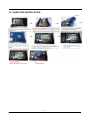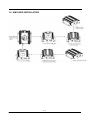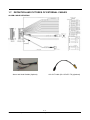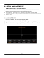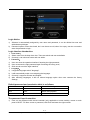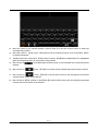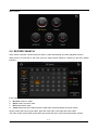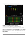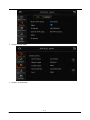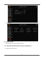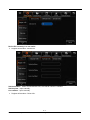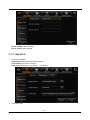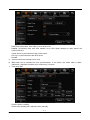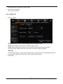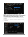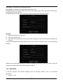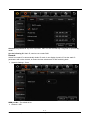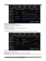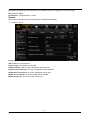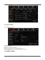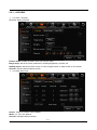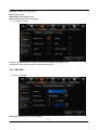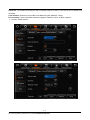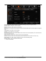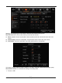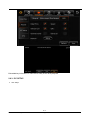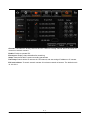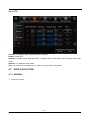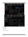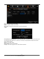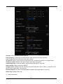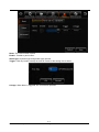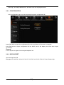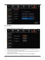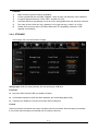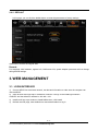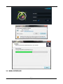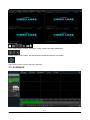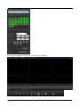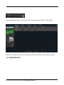
1
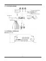
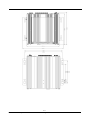
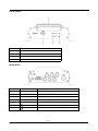
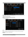
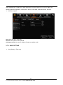
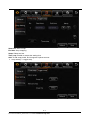
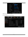
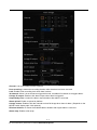
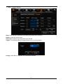
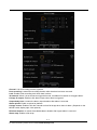
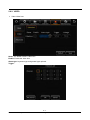
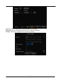
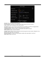
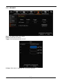
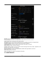
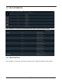
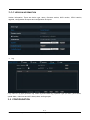
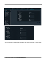
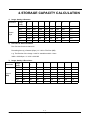
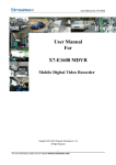
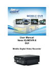
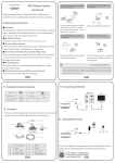
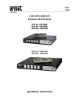
The Intelligent Security Solution User Manual For MDVRHB9605 Mobile Digital Video Recorder Hybrid Series Copyright 2013-2015, XTS Corp.All Rights Reserved 1 - 73 For more information, please visit our website www.xtscorp.com Notice The information in this manual was current when published. The manufacturer reserves the right to revise and improve its products. All specifications are therefore subject to change without any notice. The purpose of this manual is to kindly aid the user for the operation for our MDVRHB. The user shouldhave a basic understanding of computer operation and basic knowledge of how to connect peripheralsand make some settings. Copyright Under copyright laws, the content of this manual may not be copied, photocopied, reproduced, translated or reduced to any electronic medium or machine- readable form, in whole or in part, without prior written consent of XTS Corp. Copyright (2013-2015) 2 -73 For more information, please visit our website www.xtscorp.com Guarantee & Warnings 1) Electrical Apparatus Safety All installation and operation should comply with local electrical safety norms. 2) Transportation In the process of transportation, storage and installation, please avoid heavy stress, violent vibration, impact and water splashing. 3) Installation Install the equipment in accordance with the requirements, handle carefully. Do not heavily press the equipment before the MDVRHB installation is finished. 4) Requirements on Engineers & Technicians All the work of checking and maintenance should be done by qualified technicians and engineers. We do not undertake any responsibility caused by unauthorized modifications. 5) Requirements on Environment The equipment should be installed and stored in a cool and dry place, away from direct sunlight, flammable or explosive substances, etc. Keep gaps not less than 3cm around the device to facilitate ventilation for cooling. 6) Accessories Make sure to use accessories from the manufacturer recommended in the attachment. Insulate circuit ground and metal shell for all the peripherals. Before installation, please open the package and ensure that all parts are included. If there are any problems, please contact us as soon as possible. 3-73 For more information, please visit our website www.xtscorp.com Contents 1. 2. 3. PRODUCT CHARACTERISTICS................................................................................................................... 6 1.1. OVERVIEW.........................................................................................................................................6 1.2. SPECIFICATIONS............................................................................................................................. 6 1.3. SYSTEM DIAGRAM..........................................................................................................................8 1.4. EXTERNAL INTERFACE................................................................................................................. 8 1.5. HARD DISK INSTALLATION......................................................................................................... 11 1.6. SIM CARD INSTALLATION........................................................................................................... 12 1.7. DEFINITION AND PICTURES OF EXTERNAL CABLES........................................................ 13 LOCAL MANAGEMENT................................................................................................................................. 14 2.1. LOGIN INTERFACE........................................................................................................................ 14 2.2. RECORD SEARCH:........................................................................................................................17 2.3. LOG SEARCH.................................................................................................................................. 20 2.4. SYSTEM STATUS........................................................................................................................... 22 2.5. BASIC SETUP..................................................................................................................................24 2.5.1. REGISTER INFOMATION (SETUP VEHICLE INFORMATION).....................................24 2.5.2. TIME SETUP............................................................................................................................ 26 2.5.3. START UP.................................................................................................................................28 2.5.4. USER SETUP...........................................................................................................................29 2.5.5. NETWORK................................................................................................................................30 2.5.6. APPLICATION..........................................................................................................................34 2.6. SURVEILLANCE..............................................................................................................................34 2.6.1. LIVE VIEW................................................................................................................................ 35 2.6.2. RECORD...................................................................................................................................36 2.6.3. IPC SETUP............................................................................................................................... 40 2.6.4. PTZ.............................................................................................................................................42 2.7. DATA COLLECTION........................................................................................................................42 2.7.1. GENERAL................................................................................................................................. 42 2.7.2. SNAP SETTING.......................................................................................................................44 2.7.3. ECO-DRIVING ....................................................................................................................... 46 2.8. ALARM.............................................................................................................................................. 47 2.8.1. BASE..........................................................................................................................................47 2.8.2. VIDEO........................................................................................................................................54 2.8.3. ADVANCE................................................................................................................................. 57 2.9. MAINTENANCE............................................................................................................................... 58 2.9.1. CONFIGURATION...................................................................................................................59 2.9.2. DATA EXPORT.........................................................................................................................59 2.9.3. UPGRADE................................................................................................................................ 60 2.9.4. STORAGE.................................................................................................................................61 2.9.5. DEFAULT.................................................................................................................................. 62 WEB MANAGEMENT..................................................................................................................................... 62 3.1. LOGIN INTERFACE........................................................................................................................ 62 3.2. MAIN INTERFACE...........................................................................................................................63 4-73 For more information, please visit our website www.xtscorp.com 3.3. 3.4. 4. 5. PLAYBACK....................................................................................................................................... 64 MAINTENANCE............................................................................................................................... 66 3.4.1. BASIC INFORMATION........................................................................................................... 67 3.4.2. DEVICE MODULE...................................................................................................................67 3.4.3. STORAGE DEVICE................................................................................................................ 68 3.4.4. VERSION INFORMATION..................................................................................................... 69 3.5. CONFIGURATION...........................................................................................................................69 STORAGE CAPACITY CALCULATION.......................................................................................................71 FREQUENTLY ASKED QUESTIONS.......................................................................................................... 72 5-73 For more information, please visit our website www.xtscorp.com 1. PRODUCT CHARACTERISTICS 1.1. OVERVIEW MDVRHB9605 is a functional Mobile Digital Video Recorder Hybrid Series specially designed for vehicle video surveillance and remote monitoring. It has a high-speed processor and embedded operating system, combining with the most advanced H.264 video compression / decompression technology, 3G network (Optional), GPS positioning technology, as well as WIFI (Optional). It supports not only video recording in 720P, WD1, WHD1, WCIF, D1, HD1 and CIF formats, but also vehicle travel information recording and wireless data upload. With center software it also achieves alarm linkage central monitoring, remote management and playback analysis. It is easy to use with simple design, multi-functions, superioranti-vibration, flexible installation and high reliability. 1.2. SPECIFICATIONS Function Overview System Video Audio Display Preview, Recording, Playback, Network, Locating OS Linux 3.0.8 Control Mode LCDCP7-TS, MNVR-EC, Network, Mouse Input 4 channels WD1+1 channel 720P Output 1 channel Total Resource (4x30)FPS WD1 NTSC / (4x25)FPS WD1 PAL (1x30)FPS 720P Video Signal Standard Electrical level: 1Vpp Impedance: 75Ω NTSC/PAL Optional Input 5channels (1 channel IPC audio input) Output 1channel Audio Signal Standard Electrical level: 2Vpp Display Split 1/4/9 OSD GPS information, date/time Operation Interface Semi-transparent GUI Video/Audio Compression Recording Image Resolution Input impedance: 4.7kΩ alarm, vehicle No., speed, Video: H.264 Audio: ADPCM, G.711A , G.711U Analog: NTSC:WD1(928X480),WHD1(928X240), WCIF(464X240),D1(704x480),HD1(704x240), CIF(352x240); PAL:WD1(928X576),WHD1(928X288), WCIF(464X288),D1(704X576),HD1(704x288), CIF(352x288); Digital: 720P(1280X720); 6-73 For more information, please visit our website www.xtscorp.com Image Quality 1-8 levels adjustable (1 is the best) Recording Mode Boot up/Manual/Schedule/Alarm Pre-recording 0-60minutes Post-recording 0-30 minutes Playback Channel 1 channel by local playback Search Mode Date/time, channel, event 3G EVDO/WCDMA (Optional) WIFI 802.11b/g/n (Optional) Network connection WIFI/3G (Optional) IPC Ethernet 6-pin M12( 10/100M x 4, PON power supply) Locating GPS (Included) Location tracking, speed detection and time sync Storage Hard Disk 2.5" SATA hard disk x 1 (1TB included) USB USB2.0 x 1 SIM SIM slot x 1 RS232 RS232 x 1 Sensor 8 inputs, 2 outputs Speed 1 channel pulse speed detection Control panel LCDCP7-TS (Optional) Intercommunication Input I mic interface DC8-36V,Ignition signal Output 5V@1A Max Power Consumption 32W Standby Power Consumption ≈0W Dimension (L × W × H)(mm) 206.0 x 170.0 x 70.4 Weight (with hard disk) 1.24Kg Operating Temperature -40℃- +70℃(With heater) or -10℃- +70℃ Operating Relative Humidity 8%-90%(No Condense) Playback Network Interface Power Physical Characteristic Environment 7-73 For more information, please visit our website www.xtscorp.com 1.3. SYSTEM DIAGRAM 1.4. EXTERNAL INTERFACE DIMENSION (Unit: mm) 8-73 For more information, please visit our website www.xtscorp.com 9-73 For more information, please visit our website www.xtscorp.com FRONT PANEL Serial No. Description 1 Hard disk module 2 Lock 3 Status LED 4 USB interface REAR PANEL Serial No. Print Description 1 Power DC 8-36 V Power Input 2 Sensor & Serial The Interfaces of Serial Port and Switch 3 A/V IN1~4 Audio & Video Input 1-4 4 A/V OUT Audio & Video Output 5 IPC The Interface of PON Power Supply 6 GPS Antenna Interface (Included) 7 3G/WIFI Antenna Interface (Optional) 10-73 For more information, please visit our website www.xtscorp.com 1.5. HARD DISK INSTALLATION 11-73 For more information, please visit our website www.xtscorp.com 1.6. SIM CARD INSTALLATION 12-73 For more information, please visit our website www.xtscorp.com 1.7. DEFINITION AND PICTURES OF EXTERNAL CABLES ALARM CABLE DEFINITION Alarm and Serial Cables (Optional) A/V OUT Cable (For LCDCP7-TS) (Optional) 13-73 For more information, please visit our website www.xtscorp.com 2. LOCAL MANAGEMENT N9M supports 3 kinds of local setting methods: 1) Connect monitor to mobile DVR and make sure it can play real time output image. Then connect mouse to USB interface at the front panel to have MDVR parameter setting. 2) Connect the touch panel LCDCP7-TS to mobile DVR to have MDVR parameter setting. 3) Connect the MNVR-EC to USB port of mobile DVR and via WIFI you could have access to MDVR parameter setting. 2.1. LOGIN INTERFACE 1) 2) 3) When operate the device, user needs to have permission certified. Press the remote control 【LOGIN / LOCK】or【SETUP】, the login screen will pop up. Right click the mouse, the shortcut menu will pop up, left click login picture, login screen will pop up. Left click on the login button to login and right click to log out. 14-73 For more information, please visit our website www.xtscorp.com Login Notice: 1) 2) Software is automatically assigned by user name and password, it can be divided into user and administrator privileges. Password options cannot be closed, but it can be set to null; when it is empty, user do not need to enter the password to login。 Login interface Introduction: 1) 2) 1) 2) 3) 1) 2) 3) 4) User name: Select users from the drop-down box. There are admin and user as defaults. Currently, it can show two users and one admin. Password: User can enter the operation interface if entering the right password; User must enter the right password again if entering the wrong ones; Click cancel to exit the login interface; Language: It supports language switch "language". It will automatically switch once selecting the language. Currently, it supports Chinese and English; After switching languages, it will not restore language option when user restores the factory Settings; Default password and permission table is as follows: Default Password Related User Related Authority admin admin All Authorities User user Search and playback The password input Instruction: 1) User can set password with remote controller (only applicable to some models), mouse or touch panel LCDCP7-TS. Move cursor to password, click Enter and enter the right number. 15-73 For more information, please visit our website www.xtscorp.com 2) 3) 4) Move the cursor to the number position, press 【 Enter 】 or left click mouse button to select the corresponding number. Move the cursor to 【123】, press 【Enter】or mouse to choose input type, such as numbers, letters, or special characters. 【ab】means lower case letters,【123】means numbers,【AB】means capital letters; the highlighted place of background refers to the current cursor position. 5) Move Cursor to entered. , Press【Enter】or left click mouse to move between the contents that have 6) Move Cursor to , Press 【Enter】or left click mouse to delete the previous input contents. 7) Move Cursor to , Press 【Enter】or the left click mouse to exit the keypad, the entered 8) contents will be written to the edit box. Move Cursor to【Esc】 position, Press【Enter】or the left click mouse to exit the keypad, the entered contents will not be written to the edit box. 16-73 For more information, please visit our website www.xtscorp.com Main interface 2.2. RECORD SEARCH: Video search interface contains video file search, video data backup and video playback function. When there is a hard disk or SD card, enter the video search interface. Following is the REC Search interface: In the calendar, the color below the dates means: a. No color means no video. b. Green means common video. c. Red means alarm video. d. Yellow means there are alarms and the video files are automatically lock (lock video). Source: select the source of the video, there are main video, sub video and mirror video. The main record means HDD record while sub record and mirror record are dual-stream records. 17-73 For more information, please visit our website www.xtscorp.com Select the date with record, click next, and then enter the following interface: Following are the search options and search result interface: Video type: User can choose all record, alarm record or normal record. Channel: The channel is optional and mark with color that has record. The channel with gray cannot be chosen if there is no record. As to different record type, it will show different relates. Click search button in the record search detail page, user can enter then record search result page. Time Bar: Time bar shows three time points, 0 o'clock, 12 o'clock, 24 o'clock. It shows what type of videos during the time according to the marked channel. Channel No: According to the situation of video for each channel video the day, the video will be displayed on the time line. Tick the channel if user wants to playback the video. Note: channel number is displayed from 1~20, please up page up/page down button to change channel Button description Video playback: Choose the channel No., select start time to play < default start from 0 >, click the playback button to playback the video. 18-73 For more information, please visit our website www.xtscorp.com In playback interface, user can choose fast forward or fast backward to play the video, the button in the middle of screen can switch the channels. The image stops and it will not exit automatically when playing to the last video of the day. Time period settings: Click the time setting button, select start time and end time, it will back up or playback the video in the selected time period. Click clip to export the video, the file format can be.264< comprehensive file >, also can be.avi format. Video export: Select the channel that has the video files, click this button, all the video files in the effective time period will be exported to the external USB peripherals, file format can be.264<comprehensive file >, also can be avi format. User can also get out the hard drive or SD card, export and playback the video by professional software. 19-73 For more information, please visit our website www.xtscorp.com 2.3. LOG SEARCH In the log search interface, it records and displays all alarm events and login operation log. Enter the "log query”, the interface will be shown as following: Log Search interface instruction: Calendar: the date with log will be marked on the calendar with green color. Remark: There is no color classification in the “log mark”, and all are green ones. 20-73 For more information, please visit our website www.xtscorp.com Log search interface instruction: Start time: the start time for searching log files End time: the end time for searching log files Log types: classification of log search, including the operation log and alarm log and locking log Operation log search interface instruction Log includes the following information: Log time: the time when event is triggered Log name: event content Supports page up/page down and export all log files of the specified date. Do not support link to video file. Log search Alarm type: It includes all alarms, IO alarm , panic alarm and over speed alarm. Log includes the following information: 21-73 For more information, please visit our website www.xtscorp.com Log time: the time when event is triggered Log name: event content Supports page up/page down and export all log files of the specified date. Supports link to video file, click on button to playback video files Lock log search Log includes the following information: Log time: the time of when event triggered. Log name: event content Log will be recorded according to channel number, each channel will have a lock log file. Support page up and page down. Can’t export all log files of the specified date. Can link to video file, click on button to playback video files. Unlock: Select log, and unlock it. Then the alarm log of lock will be cleared. Remark: When lock the video file, system will record alarm log and lock log. The locked video file can only be unlocked from alarm log. 2.4. SYSTEM STATUS User can login the interface with no access restrictions. System- Version information System- Modules 22-73 For more information, please visit our website www.xtscorp.com System-Server status System - Environment 23-73 For more information, please visit our website www.xtscorp.com System-Storage: 2.5. BASIC SETUP Click setup button and enter the following interfaces: 2.5.1. REGISTER INFOMATION (SETUP VEHICLE INFORMATION) Register information-Device info: 24-73 For more information, please visit our website www.xtscorp.com Device ID: Currently, it is not useful. Register information- Vehicle info Vehicle Number:When connected with PAD, the vehicle number is needed. Vehicle plate:Input manually. Line number:Input manually. Register information—Driver info: 25-73 For more information, please visit our website www.xtscorp.com Driver number: Input manually. Driver name: Input manually. 2.5.2. TIME SETUP Time setup-General Date format: Setup the date format of device Time format: 24 hours or 12 hours Time zone: Range from -12th district ~ +13th district Time-Time Sync 26-73 For more information, please visit our website www.xtscorp.com 1) 2) Date/Time: Device time, from 2000-01-01 to 2036-12-31 Satellite: Synchronize time with GPS satellite. Once GPS signal changes to valid, device will synchronize time Center Server: synchronize time with center server NTP sync: synchronize time with NTP server Remark: Synchronize time according to time zone Multi-mode can be selected for time synchronization. If one works, the others take no affect. Otherwise, it switches to another sync mode every 5 minutes. Time setup-DST Enable: Select to enable Offset: After enabling DST, adjust the hour manually 27-73 For more information, please visit our website www.xtscorp.com Mode: Setup DST according to week or date Start: Time to start DST End: Time to end DST 2.5.3. START UP Startup-ON/OFF ON/OFF mode: 3 modes, including ignition, timer and ignition or timer. Ignition: Input ignition delay time for shutdown delay function Timer: When setup the start mode as Timer, please setup the start time and end time Under this mode, MDVR’s start up or shut down time will not affect the ignition. Remark: If use setup as Ignition or Timer Mode, Ignition ON or Timer start time can trigger MDVR start up. And only when Ignition off and Timer end time, MDVR will shut down. Start-Sleep 28-73 For more information, please visit our website www.xtscorp.com Sleep Mode: Currently, there is only no consumption standby mode available. Low Volta protect: Enabling the low voltage shutdown protection mode selected. Battery low voltage: Protect the vehicle battery. When consistently below the standard value, it will countdown shutdown. As for a 12V vehicle, the default is 9V, while a 24V vehicle is 21V. Voltage start up: low-voltage protection, when the battery voltage is consistently greater than the standard value, it will automatically boot. As for a 12V vehicle, the default is 12.5V, while a 24V vehicle is 24.5V. Low volt upload: The low-voltage protection will be reported to the platform after it is ticked. 2.5.4. USER SETUP In the basic settings, click user settings, enter the following interface, user can enter setting menu. 29-73 For more information, please visit our website www.xtscorp.com User name: The default ones are admin and user. User Group: It is divided into administrator and ordinary user. It supports delete user function. Select the user and click "Delete User" button. Please be noted that the administrator cannot be deleted. It supports add user function. Click "Add User" button, then enter the following interface. Remark: 1) 2) 3) Only administrators can add users. Users can add up to two. User name cannot be empty, not the same with the existed user name while the user password can be empty. User name and password can be modified. Select a user, click the "Edit User" button, enter the following interface: Modify the user name and password to confirm the operation temporarily. There is no need to verify the old password, Administrator user name cannot be modified. 2.5.5. NETWORK In the basic settings, click Network Settings, enter the following interface, user can set network parameters. Network - Local 30-73 For more information, please visit our website www.xtscorp.com Automatically obtain IP: Dynamic acquisition, DNS can also be statically configured to dynamically obtain. Use the following IP: Static IP, need to use a static DNS. Remark: Switch from static IP to automatically obtain IP mode, it can display dynamic IP, but the static IP parameters will not be covered, to restore the last saved static IP after switching back. Network Settings - Ports: WEB port No.: The default is 80. Network- WIFI 31-73 For more information, please visit our website www.xtscorp.com Enable: Select to enable WIFI ESSID: Manually input the address of AP Encryption: It supports NONE, WEP and WPA Password: Manually input Static IP: Select to use static IP, or MDVR will get dynamic IP Network-Communication: Dialing wireless network, user needs to choose the module type and setup dialing parameters When entering the dialing setup interface, it searches the wireless module type automatically. It shows No Service when there is no module. Network type: The default one is Mix, 2G/3G and 2G/3G/4G (Optional). Dialing parameter:It includes access point, user name, password, data service number, and enter SIM 32-73 For more information, please visit our website www.xtscorp.com parameters provided by the manufacturer. The default is empty, the program comes with empty arguments by dialing. Certification:Supports PAP or CHAP. Remark: When there is SIM and normal 3G/4G signal, it will dial automatically. Network- Server Center server: It supports 6 servers at most, and server 1 cannot be deleted manually. ON: Enable the current server. Protocol type: The default one is N9M. Enable network: There is local, WIFI and module optional Register server address: To run the registration server address. Registration server port: To run the registration server port. Media server address: To run the media server address. Media server port: To run the media server port. 33-73 For more information, please visit our website www.xtscorp.com 2.5.6. APPLICATION Application-FTP Client FTP Enable: Enable FTP. Server: To run FTP server address. Port: To run FTP server port. (The default one is 21.) User name/password: The accounts distributed by FTP server. 2.6. SURVEILLANCE 34-73 For more information, please visit our website www.xtscorp.com 2.6.1. LIVE VIEW Live view-->Preview Real-time Setting Interface: Preview audio: Enable the audio when live view the video. Image setup: Set the live-view parameters, including brightness, contrast, etc. Startup Screen: Set the live-view screen, it can be single-screen or quad screen or nine screen Channel: Set the channel when live-view Live view-Auto Loop: Screen: Totally 32 screens can be added. Mode: 1x1, 2x2, 3x3 optional. Channel: Included channel number. 35-73 For more information, please visit our website www.xtscorp.com Duration: Duration for each screen. Edit: Delete or Edit. Add screen: Add polling screen Auto polling: Enable the auto pulling Live view-Live OSD : It displays the information on screen, such as time, speed, license plate, GPS... The default is only the time, and the position cannot be set. 2.6.2. RECORD Record-->General Video type: Default is PAL, NTSC optional 36-73 For more information, please visit our website www.xtscorp.com Overwrite: The earliest recording file will be deleted while the HDD or SD card is full to realize loop recording. Lock duration: Protect the record file to be deleted by fault, default is 7 days. Pre-recording: Pre-record before the alarm happens. Default is 15min, 0-60min optional. Record-->Main Stream: 37-73 For more information, please visit our website www.xtscorp.com Channel: The total channel numbers of the device, including analog and digital channels. Channel name: Change the name manually. Enable: Enable the main stream record function Resolution: The analog channel supports D1/HD1/CIF/WD1/WHD1/WCIF while the digital one supports 720P. Frame Rate: Frame Rate of the recording. Quality: Picture Quality of the recording. Record mode: Ignition, Time, Event optional. Each channel can be set separately. The sub-stream and mirror record are the same Audio: Enable the audio. Note: Audio cannot be record separately I frame: Enable to let the frame rate invalid, record file that does not have alarm is I frame only. Alarm quality: The alarm image is different from the normal recording image. Encode mode: It supports VBR and CBR modes. Record- Dual stream 38-73 For more information, please visit our website www.xtscorp.com Storage: The storage type for sub stream, internal SD and external SD optional. Record mode: Mirror record, alarm back-up record and sub stream. Mirror record: Channel is selectable. Video resolution and frame rate are the same with main stream. Alarm backup: Channel is selectable. The parameters are the same with main stream Sub stream: Channel is selectable. Recording parameters are configurable Sub stream includes channel number, enable or not, audio, resolution, frame rate and image quality. Sub stream channel: It is selectable according to recording mode. Record-->OSD 39-73 For more information, please visit our website www.xtscorp.com Embedded key information to video file for easily check when playback. 2.6.3. IPC SETUP IPC setup: 40-73 For more information, please visit our website www.xtscorp.com Channel: It includes the analog channels and IPC channels. Analog channel will not be shown if it connects to network camera. Enable: Enable to operate IPC. IP and port: Display channel details after searching. Setup: Search and edit IP camera recording parameters Fast setup: Search all the IP cameras in LAN network, and auto assign IP address to IP camera. IPC local address: To search network camera of local area network at Intranet. The default one is 10.100.100.1. 41-73 For more information, please visit our website www.xtscorp.com 2.6.4. PTZ Channel: It includes analog channels and IPC channels. Enable: Enable PTZ. Operate: It includes serial, N9M and ONVIF. It supports Pelco-D and Pelco-P PTZ protocols with serial mode. Address: It is valid with serial mode. Test: It is to test PTZ is available or not. Click it to pop up PTZ control panel. 2.7. DATA COLLECTION 2.7.1. GENERAL General-->Sensor 42-73 For more information, please visit our website www.xtscorp.com Sensor number: The total alarm input numbers of MDVR. Sensor name: IO sensor name, it can set manually. The sensor name of alarm setting interface will update synchronously after setting. OSD name: The information embedded to video image. Copy: Copy the configuration and use it for other sensors. General-->Serial port: RS232-1 and RS232-2, with the following features: three axis sensor, expansion, 485 bus and GPS data. RS485-1 and RS485-2, with the following features: PTZ, control panel, 485 bus and GPS data. Baud Rate: 2400-115200, 9 classes optional. Remarks: 43-73 For more information, please visit our website www.xtscorp.com Some models have 4 serial ports, while others have only one RS232 port, but it can realize the following features: expansion, control panel, 485 bus, GPS data, three axis sensor, and PTZ. General-->speed Unit: KM/H and MPH selectable. Source: GPS, pulse or both optional. Calibration mode: No need to calibrate if setup as satellite mode. 2.7.2. SNAP SETTING Snap Setting-->Time snap 44-73 For more information, please visit our website www.xtscorp.com Start time: Start to snap. End time: Stop snapping. Setup: Delete and set. Time snap: Enable to snap at the setting time. Add: To add snap period, and it supports 8 pieces at most. Snap Setting--> Trigger snap 45-73 For more information, please visit our website www.xtscorp.com Trigger snap: It snaps when alarm is trigger. 2.7.3. ECO-DRIVING (It is still developing.) 46-73 For more information, please visit our website www.xtscorp.com 2.8. ALARM 2.8.1. BASE Base-->Speed alarm 47-73 For more information, please visit our website www.xtscorp.com Name: The current name is over speed Enable:Enable or disable, tick to enable Alarm type: It includes the following types, important and general. Trigger: Over speed pre alarm difference: To set the pre alarm data. For example, if speed is 60 km/hour, and over speed pre alarm difference is 10 km/hour, TSS sends over speed alarm broadcast and records when it reaches 50 km/h. Speed: It is the alarm speed. Alarm duration: Alarm output duration Linkage: When alarm triggered, link to other business operation. 48-73 For more information, please visit our website www.xtscorp.com Channel: Link to recording channel, optional. Post recording: It means the recording duration after the alarm has been removed. Lock: Enable to link recording lock when there is alarm. 3G network: When it is set as sensor trigger dial mode, it enables 3G network as it triggers alarm. Linkage IO output: Enable to link alarm output when alarm is triggered. Output delay time: It means the alarm output duration after alarm is removed. Alarm upload: Enable to upload to platform. Linkage screen: Enable to link the channel to show full image when there is alarm. ( Depends on the MDVR model, display split 1/4/9 optional.) PB alarm duration: It means the available alarm duration after urgent alarm is removed. Alarm snap: Enable to link snap. Base- Panic alarm: 49-73 For more information, please visit our website www.xtscorp.com Name: The current name is panic. Enable:Enable to panic button. Alarm type: Important type and general type optional. Trigger: Click any button to delay the time till it reaches the setting time to alarm. Linkage: When alarm is triggered, link to business operation. 50-73 For more information, please visit our website www.xtscorp.com Channel: Link to recording channel, optional. Post recording: It means the recording duration after the alarm has been removed. Lock: Enable to link recording lock when there is alarm. 3G network: When it is set as sensor trigger dial mode, it enables 3G network as it triggers alarm. Linkage IO output: Enable to link alarm output when alarm is triggered. Output delay time: It means the alarm output duration after alarm is removed. Alarm upload: Enable to upload to platform. Linkage screen: Enable to link the channel to show full image when there is alarm. (Depends on the MDVR model, display split 1/4/9 optional.) PB alarm duration: It means the available alarm duration after urgent alarm is removed. Alarm snap: Enable to link snap. 51-73 For more information, please visit our website www.xtscorp.com Base – IO alarm interface: Name: From Sensor1 to Sensor8 (It includes all the alarm input numbers.) Enable: Enable the sensor alarm. Alarm type: Important type and general type optional. Trigger: Low and high optional. It triggers alarm when it is low as default. Linkage: When alarm is triggered, link to business operation. 52-73 For more information, please visit our website www.xtscorp.com Channel: Link to recording channel, optional. Post recording: It means the recording duration after the alarm has been removed. Lock: Enable to link recording lock when there is alarm. 3G network: When it is set as sensor trigger dial mode, it enables 3G network as it triggers alarm. Linkage IO output: Enable to link alarm output when alarm is triggered. Output delay time: It means the alarm output duration after alarm is removed. Alarm upload: Enable to upload to platform. Linkage screen: Enable to link the channel to show full image when there is alarm. (Depends on the MDVR model, display split 1/4/9 optional.) PB alarm duration: It means the available alarm duration after urgent alarm is removed. Alarm snap: Enable to link snap. 53-73 For more information, please visit our website www.xtscorp.com 2.8.2. VIDEO Video-Video loss Name: The default name is video loss. Enable: Enable the video loss. Alarm type: Important type and general type optional. Trigger: 54-73 For more information, please visit our website www.xtscorp.com Video loss set: It includes all video channels that can be selected. Set period: Set the checking period when video loss alarm is triggered. Linkage: When alarm is triggered, link to business operation. 55-73 For more information, please visit our website www.xtscorp.com Channel: Link to recording channel, optional. Post recording: It means the recording duration after the alarm has been removed. Lock: Enable to link recording lock when there is alarm. 3G network: When it is set as sensor trigger dial mode, it enables 3G network as it triggers alarm. Linkage IO output: Enable to link alarm output when alarm is triggered. Output delay time: It means the alarm output duration after alarm is removed. Alarm upload: Enable to upload to platform. Linkage screen: Enable to link the channel to show full image when there is alarm. (Depends on the MDVR model, display split 1/4/9 optional.) PB alarm duration: It means the available alarm duration after urgent alarm is removed. Alarm snap: Enable to link snap. 56-73 For more information, please visit our website www.xtscorp.com 2.8.3. ADVANCE Name: The default name is ACC alarm. Enable: Enable the ACC alarm. Trigger: Set the threshold value of X/Y/Z. Linkage: When alarm is triggered, link to business operation. 57-73 For more information, please visit our website www.xtscorp.com Channel: Link to recording channel, optional. Post recording: It means the recording duration after the alarm has been removed. Lock: Enable to link recording lock when there is alarm. 3G network: When it is set as sensor trigger dial mode, it enables 3G network as it triggers alarm. Linkage IO output: Enable to link alarm output when alarm is triggered. Output delay time: It means the alarm output duration after alarm is removed. Alarm upload: Enable to upload to platform. Linkage screen: Enable to link the channel to show full image when there is alarm. (Depends on the MDVR model, display split 1/4/9 optional.) PB alarm duration: It means the available alarm duration after urgent alarm is removed. Alarm snap: Enable to link snap. X:0.0, Y:0.0, Z:0.0: The real time acceleration information. 2.9. MAINTENANCE 58-73 For more information, please visit our website www.xtscorp.com After login, click setup>Maintenance, and then enter into the page as follow. 2.9.1. CONFIGURATION In the configuration page, user can export and import the configuration file. Insert flash drive to export the configuration file to the root folder, the file name is ConfigFile Insert flash drive to import configuration file into MDVR, and it will display the notice when import successfully. Remark: It won’t import the register info and speed adaption info. 2.9.2. DATA EXPORT User can export any file. File type: GPS data file, vehicle info file, ACC info file, Can info file, Dial info file and Captured pic. 59-73 For more information, please visit our website www.xtscorp.com 2.9.3. UPGRADE In the page of upgrade, user can upgrade software. Put the upgrade file in flash drive. Currently, device firmware, microcontrollers firmware, CP4 firmware and IPC firmware can be put inside. Insert flash drive and enter the upgrade interface, click software upgrade and it will indicate that upgrade file is importing. MDVR reboot up and enter into upgrade interface after importing successfully. 60-73 For more information, please visit our website www.xtscorp.com Remark: 1) 2) 3) 4) 5) 6) Make sure don’t power off during upgrading. Put the upgrade file into the folder “upgrade”, which is at the root directory if the USB drive It support upgrade firmware, LOGO, MCU, and MCU for CP4. Firmware and MCU will package in one file, and it will upgrade MCU first, and then firmware. The name of the LOGO are: logo_update(10.12.15).jpg and logo_cvbs(11.12.15).jpg Please don’t put many files in the same folder when it is upgrading, otherwise, it will upgrade one randomly. 2.9.4. STORAGE In this page, user can format all the storage. Storage type: HDD, SD card (Internal), SD card (External), USB drive Free/Total Not exist: Didn’t find the HDD (not install or broken) Unformatted: Means the HDD has been detected, but unformatted.(New HDD) Capacity info: Display the correct info means HDD working fine Format: Click format and it will refresh the current formatted volume information after formatting successfully. It can record after formatting successfully and no need to reboot up. 61-73 For more information, please visit our website www.xtscorp.com 2.9.5. DEFAULT In this page, you can click the default button to reset the parameters to factory settings. Click reset to restore the original data. Remark: For, language, MAC address, register info, CMS server info, speed adaption parameter will not change during default settings. 3. WEB MANAGEMENT 3.1. LOGIN INTERFACE 1) Connect MDVR into local area network, set relevant information to make sure the computer can visit the MDVR. 2) Open browser and input http:// IP address of MDVR. It will go to the WEB login interface of MDVR. And the default IP address is 192.168.1.100 3) Interface will pop up a window to install N9M activex, click install. 4) Refresh the web page, enter default user name admin/admin to log in. 62-73 For more information, please visit our website www.xtscorp.com 3.2. MAIN INTERFACE 63-73 For more information, please visit our website www.xtscorp.com Icons: quad, 9-split, preview, next page, sound, capture and video parameters. Stream switch: main stream, sub-stream and network transmission sub stream. Log out: log out and come to the log in interface 3.3. PLAYBACK 64-73 For more information, please visit our website www.xtscorp.com If the date is marked as color green, it means there is recording. 65-73 For more information, please visit our website www.xtscorp.com Recording playback window: Video window, play time-line, play control button, window switch... Record list: It displays all the record. Click backup download video file to local computer hard disk. 3.4. MAINTENANCE 66-73 For more information, please visit our website www.xtscorp.com 3.4.1. BASIC INFORMATION Basic information: It contains the current state & history state of channel video and storage. 3.4.2. DEVICE MODULE Device module: It is about the current state of module, WIFI module and satellite location module. 67-73 For more information, please visit our website www.xtscorp.com 3.4.3. STORAGE DEVICE Storage device: There are the volume information & format operation of storage (hard disk/flash drive/SD card), and the path of snap & record backup. 68-73 For more information, please visit our website www.xtscorp.com 3.4.4. VERSION INFORMATION Version information: There are device type, name, firmware version, MCU version, CP3/4 version, upgrade, configuration file export and configuration file import. Log Log: There is Log type (operation log, alarm log and locked log), operation type (IO alarm, panel alarm, speed alarm, video loss and ACC alarm) date, and log export. 3.5. CONFIGURATION 69-73 For more information, please visit our website www.xtscorp.com The parameter setting is the same as the local setting. User can view the operation at the local setting. 70-73 For more information, please visit our website www.xtscorp.com 4.STORAGE CAPACITY CALCULATION 1) Image Quality & Streams Resolution Stream Kbps 2) Image quality 1 2 3 4 5 6 7 8 720P 6144 4800 4128 3456 2784 2112 1440 768 WD1 2662 1997 1599 1331 1170 1040 936 832 WHD1 1664 1248 998 832 728 650 585 520 WCIF 1040 780 624 520 455 405 364 325 D1 2048 1536 1230 1024 900 800 720 640 HD1 1280 960 768 640 560 500 450 400 CIF 800 600 480 400 350 312 280 250 Record File Size Calculation Rec. file size for each channel is: Recording time (s) x Stream (Kbps) / 8 / 1024 = File Size (MB) e.g. The file size of the Image 1 with D1 resolution within 1 hour: 3600 x 2048 Kbps / 8 / 1024 = 900 MB 3) Image Quality & Resolution Resolution Record (MB) Image quality 1 2 3 4 5 6 7 8 720P 2700 2109 1814 1518 1223 928 632 337 WD1 1170 878 702 585 514 456 411 365 WHD1 731 549 438 365 320 285 257 229 WCIF 456 343 274 229 199 178 160 143 D1 900 675 540 450 395 351 316 281 HD1 562 422 337 281 246 219 198 176 CIF 351 264 211 176 153 137 123 110 71-73 For more information, please visit our website www.xtscorp.com 5.FREQUENTLY ASKED QUESTIONS 1) The system can’t start? Usually this problem results from the incorrect power connection. Please follow below steps to check the power connection: 1. Check the input power, whether the power wire is connected correctly, whether the ground wire is connected back to the battery, and whether the fuse on the power wire is in good condition. 2. Check whether the ACC signal wire input to the power is with voltage higher than 7 V. 3. Check whether the device key is closed. 2) The MDVR restarts uninterruptedly? Please follow below steps to check it: 1. Check whether the voltage of MDVR is insufficient. If the voltage is less than the start-up voltage of the device, the device would always restart. 2. The problem in hard disk/SD card may cause the failure to start. Take off the storage part and check whether it is broken down. 3) The device can’t record? Usually this problem results from the storage disk or camera. Please follow below steps to check it: 1. Check whether the storage disk is installed, whether it is in good contact, and whether the disk can be read normally in computer. 2. Check whether the storage disk is formatted. The storage disk should be formatted before normally storing record files. 3. Check whether there is video signal input into the device from camera, and whether there is video/image on the screen. 4) There is no voice in record file? Please follow below steps to check it: 1. Check whether there is an external pickup, or whether the camera features with the function of audio collection. 2. Access to Video Channel Settings, check if Audio is set on. 3. There must be video input into the channel for recording and it must record normally. 5) The GPS works abnormally? Please follow below steps to check it: 1. Check whether the GPS antenna is installed correctly. There is a silk print logo on the GPS antenna holder behind the host device. 2. Check whether the antenna receiver is sheltered. It should not be covered by any stuff, which may cause it not to receive signals. 3. Environmental influence such as tree shades, being inside tunnel, driving near tall building or elevated roads, thunderstorms or other weather influence, etc. can also cause signal loss or receiving wrong signals. 6) The device can’t shutdown in ignition switch mode? Please follow below steps to check it: 1. Check if the ACC line connection mode is correct; and check whether there is voltage on ACC yellow line when the key is turned off. 2. If the device has been set with schedule recording, it can’t shutdown if it is still during recording time 72-73 For more information, please visit our website www.xtscorp.com of the task table. 7) Which IP waterproof level does MNVRHB device support? Currently, support waterproof IP 54. 8) How to install the WIFI antenna? The antenna must be installed on unobstructed place of the roof, and be fixed with glue. 9) The device cannot be shut down when in ignition ON/OFF mode. Check if the ACC signal wiring is correct and if there is voltage for ACC signal line after the key is turned off . If you have set timing recording, and at the current time it is still in task recording, the device may be impossible to be shut down. 10) GPS anomaly. Check if the GPS antenna is properly installed. There is silkscreen GPS identification on the GPS antenna pedestal on the back of the MDVR device. Check if the antenna connector is blocked and make sure the antenna connector not be covered by other things. Trees block, being inside the tunnel, driving near tall buildings or viaduct, thunderstorms and other environmental effects may also cause to receive no GPS signal or error signal. 11) No voice in video files. See if there is an external microphone, or if the camera cannot capture audio; Enter into the video channel settings, then check if the audio is open; Ensure video input and normal recording, on which the audio recording channels must be based. 12) The device doesn’t record. Make sure the storage part is installed and of fine contact, the data can be read on PC, and the storage device is not formatted. Check if there are video signal input to the main device, and whether there are video images in the channel pictures. 13) Why has the MDVR device always been in a state of restart? Check whether the MDVR device voltage is insufficient. If the device voltage does not reach the start voltage, the device will restart. Hard disk or SD card may cause the MDVR device unable to start. You need to remove the storage device and then boot up to verify whether it is caused by the storage device. 14) Why the MDVR device cannot start? Check the device input power to see if the power wiring is correct, if there is ground wire connected back to the battery, and if the fuse of the power wire is in good condition; Check whether there is voltage(more than 7V) on power input ACC signal wire; Check whether the hard disk key is turned off. 15) What is the log in user name and password for new device? The default user name and password are both “admin”. The device password can be set as empty. 16) How to update the firmware? Change the previous file folder name “dvrupgrade” to “upgrade”. Change the file name FWX15-0401-05-01-V01V01V01V491087 to RMMDVR_X5_III_T2014111005_convert 17) In the ON/OFF of basic settings, the low voltage protection is 8V, why? After testing, when the battery is lower than 8V, the voltage will lower down quickly. Therefore the lowest voltage is set to be 8V. When it is lower than 8V, the MDVR device will recognize it as external power-off and then enter into shutdown state. 73-73 8870 NW 18th Terrace, Doral FL 33172 USA Phone: 305.863.7779 Fax: 305.863.7478 Toll Free: 1.855.797.8XTS www.xtscorp.com ® 2015 All Rights Reserved