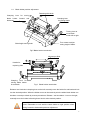
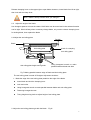
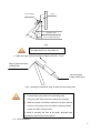
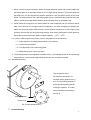
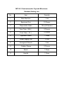
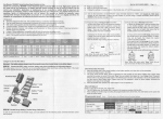
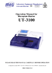
1
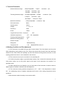
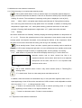
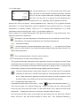
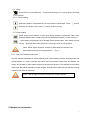
Operation Manual for
Cryostat
MIT-30-1
PLEASE READ THIS MANUAL CAREFULLY BEFORE OPERATION
3, Hagavish st. Israel 58817 Tel: 972 3 5595252, Fax: 972 3 5594529 [email protected]
MRC.VER.01-3.12
Helpful Suggestions:
User manual is a part of the instrument. The user should read this user manual
carefully before first installation and operating the machine, and put this manual
beside the instrument to refer it when meet problems.
MIT-30-1 must be operated by user who is trained. Before operation, please carefully
read operation instruction first to know operation steps and process.
Unit must ship upright. If this unit was shipped lying down or stored lying down then it
MUST stand upright for 36 hours before use.
Do not put instrument under extreme temperature and high air humidity environment.
Failure to follow this will cause instrument severe damage
Do not place instrument directly under sunshine or outlets of air condition
No other obstruct around the instrument in 30cm distance.
Check your power socket is well grounded. Ensure that power supply is stable,
constant and adequate. Compressor requires a start-up current between45 and 50A.
Therefore, the professional electrical engineer must inspect the electric circuit before
installation to meet smooth operation of the instrument requirement.
Blade is sharp, beware when you change it.
Do not place blade anywhere with the cutting edge facing upwards.
Before changing specimens always lock the hand wheel .
In case of malfunction, contact our company. Don’t try to solve it by your own risk.
1. Introduction
Model MIT-30-1 Semi-automatic Cryostat Microtome, national regulated 1st class medical
equipment, is a rapid pathological section instrument to human and animal body tissues. It can be
widely used for pathological diagnosis, analysis and research in hospitals, medical colleges, legal
medical experts and propagation institutes.
The instrument mainly consists of 4 parts:
1. The computer controlled panel is on the upper part to display the temperature and the working
condition of the instrument.
2.
. The center part is the constant low temperature room to rapidly freeze the vivid tissue and to
conduct the cutting area.
3.
. Behind is the mechanical transmission and motor drive.
4.
. The lower part is the compressor unit for cooling.
2. Scope of Application
Pathological section and study histology of plant, animal or human being.
1
3. Technical Parameter
Section thickness range: 1-80µm Adjustable ,1-20µm , Increment:1µm;
20-40µm, Increment:2µm;
40-80µm, Increment:5µm;
Trimming thickness range: 10-400µm Adjustable,10-50µm , Increment:5µm;
5-100µm , Increment:10µm;
100-400µm , Increment:50µm;
Specimen retraction:
0-95µm Adjustable ,Increment:5µm
Horizontal stroke:
20mm
Vertical stroke:
60mm
Voltage:
AC 220V±22V
Frequency:
50Hz
Power:
850W
Largest start-up current(5 second)
45A
Chamber temperature:
-10℃~-30℃ Adjustable
Freezing shelf temperature:
≤-40℃
Number of freezing station:
10
Pelletier number:
1
Refrigerant:
R404a,300±10g
Compressor oil:
0.6L
EMKARATE RL-22S, ICI
4. Working Condition and Pre-adjustment
4.1 The instrument is movable floor type with 4 caster wheels. Two front wheels can be up and
down adjusted by turning knobs on the foot. These front wheels only function when the instrument
needs to move. After remove the package, put the front wheels on the ground and move it to the
working position and secure it, then disable the front wheels.
4.2 The instrument can only be used after 4 hours standing still.
4.3 Confirm the power supply is grounded (triple socket), then connect the instrument with the
main power socket, turn on the power switch at the back of the instrument, the machine is in
operation mode.
4.4 Other materials are not allowed to put on both sides of the instrument. At least to leave a
300mm space to facilitate ventilation and heat dispersion.
4.5 The instrument working ambient temperature is +5℃~+28℃. If the temperature is above
26℃, air conditioning must be installed; otherwise the life time of the cooling compressor will be
shortened.
4.6 Environment relative humidity is no more than 80%.
2
High temperature or humidity will influence freezing effect.
5. Operation
5.1 Operation panel (Fig 1)
Left area
Right area
Middle area
Fig 1
5.2 Turning the Instrument On
First connect power line on the rear of cryostat, then turn on switch on the rear of cryostat.
Cryostat is under working condition and feeding arm go back original position. Compressor starts
to work after turning on power switch and freezing chamber begins to cool down. (It depend the
interval of turning off and on, if within 3 minutes, the instrument needs to wait another 3 minutes,
otherwise machine easy to damage). Two red LED lights above right area , first one is for big
compressor and second is small compress. When compressor starts to work, the first light is on.
If press fast freezing button, second light is on.
Control board is separated into three area, left area, middle area and right area. Left area is for
software switch and fast defrost buttons; middle area is for section/trimming setting, peltier and
stand by function control; right area is for time and temperature setting. Small control panel on
the left of cryostat controls clamp feeding, illumination and UV sterilizing.
5.3 Left area control buttons introduction
5.3.1 Software switch
Press this button to switch on or off operation panel. If indicator is on, user may adjust
time, defrost, temperature and so on. Otherwise, indicator is off and panel locked. User
cannot do any operation.
5.3.2 Immediate defrost
This is fast defrost button. Press it to activate fast defrost function and indicator light is on,
system goes into fast defrost mode. It takes about 6 minutes to defrost. Press”
” button
again to stop fast defrost working, indicator light goes out simultaneously. Freezing recovers
after 25 seconds. If system automatically enter time defrost mode, indicator lights up too. Press
button again to stop defrost and indicator light goes out.
3
5.4 Middle area control buttons introduction
5.4.1 Peltier freezing ( It is invalid under stand by mode)
This is peltier switch button. Press it, indicator light is on and peltier element begins to
work and cools down the stations. Forth line on the screen shows [015] to indicate peltier
working 15 minutes. The countdown of remaining cooling time is displayed, such as [014],
[013] ……”[002]”, “[001]”, until peltier stops freezing and indicator off. During Peltier working
time. User may press this button to stop peltier when it is activated. In addition, if freezing shelf
temperature is higher than -10℃ when peltier working, peltier will self close. On the same
principle, if freezing shelf temperature is higher than -10℃, peltier cannot be activated.
5.4.2
Standby
We call the instrument into “Standby” mode by keeping the freezing chamber at a temperature of
-4℃ to -9℃ . This time the operational time of the compressor is less than the stop time with
average power consumption decreased, more prolongs the lifetime of the compressor. When
long time do not use the instrument for slicing, then let it go into “Standby” mode.
This is standby button. Press it one time, system goes into standby mode or transfer to
work state. LCD screen background light tells us how to differentiate from standby and normal
working. If background light is in dark, it is standby mode, On the contrast, it is working.
5.4.3
After switch on cryostat, the first LCD will display data as Fig 2. First line Sect is to
Sect
Retr
No
Tn
6
15
0
0
represent section and its value; second line Retr is to
represent retraction and its value; third line No is to represent
total pieces and its value; forth line Tn is to represent total
thickness and its value.
Fig 2
This is mode selection button. Press it may select Section (Sect) or Trimming(Tim)
working mode.
“C” is clear button. Push it to clear total pieces and thickness into “0”.
In addition, these two buttons are combination keys. If user push them together, there is one “*”
signal appearing in front of Rect on the second line of LCD to show it under adjustable condition.
User may press “+” or “-“ to change retraction value.
“+” button is to increase value. Push it to add on section (trimming) value. If “*” signal
appearing in front of Rect, it is to adjust retraction value.
“-” button is to decrease value. Function is same as above.
5.5 Right area control buttons introduction
4
5.5.1 Clock adjust
After cryostat switching on, it is self running under current time
Day
Time
T0
T1
1
12:00
16 [-18]
16 [off]
Fig 3
state, right LCD on control panel is showing information and data
as Fig 3. We call it initial mode when cryostat get power supply
and reset. First line Day is to present current operational day,
numbers from 1 to 7 separately stand for Monday to Sunday.
Second line Time is to present current operational time. Third line T0 is to present chamber
temperature. It is actual temperature value for operational room; following value in [ ] is setting
temperature of freezing chamber. Forth line T1 is freezing shelf temperature. It is actual
temperature value for freezing shelf. “Off” in [ ] is to stand for peltier off.
User can press “D” to adjust working day. Then press hour button ”H” and minute button “M” to
adjust hour and minute respectively.
This button is to select temperature. Press button per time, the third line on the LCD will
shift between T0( Chamber temperature) and T2 (Clamp temperature).
5.5.2
Temperature setting
Press this button to increase temperature value. Value in [ ] in the third line on LCD will
add on. If LCD shows T0, it is to adjust freezing chamber setting; otherwise it shows T2 to
adjust clamp temperature.
This is decreasing button. Function is same as above.
5.5.3 Fast freezing (It is invalid under standby mode).
This cryostat has double compressors. Big compressor freezes for chamber and shelf. Small
compressor does not work if system is in stand by, when system goes back to normal working
from stand by, fast freezing is activated. Small compressor is going to start in 3 minutes and
freeze clamp. Operator may cancel fast freezing regarding their own situation.
Press fast freezing button, button green indicator is on and with sound of compressor
initializing. At same time, red LED on the panel for small compressor indicator should
be on. Clamp temperature gradually decrease with working of small compressor. Press
this button again, two indicators are off and small compressor stop working.
5.5.4 Programming start-of-work time
If second line on the LCD is in Time mode ,Press “
“ button until second line shows “TON”.
Then user can press “D” to adjust working day. Press “D” button one time, working day will
minors one day. Then press hour button ”H” and minute button “M” to adjust hour and minute
respectively. (Definite time ivterval is 10 munites, automatic defrost is same).
User can press “W-DAY” button to set single day start-of-work time too. After push “W-DAY”
button, first line in the LCD should change to “Dwork 1&6”. “1&6” represents Monday to
5
Saturday. Press “D” button to select working day, then press ”H” and “M” buttons to adjust hour
and minute respectively. System automaticlly set 24 hours for nonworking day and goes into
standby mode to reduce electricity consumption.
5.5.5
Programming end-of-work time
Press
button as many time as “TOff” displaying on the second line on LCD;it stands for
system enter end-of-work time programming; setting method is same as start-of-work
programming. After operation press
again to return working mode, and lock start/end
setting time.
Note: Please make LCD go back to initial contition mode after setting.
5.5.6 Programming defrost definite time
This is defrost definite time button. Under initial mode after pressing, first line on the
LCD displays “Defrost”. Second line displays “Time”. User may press ”H” and “M”
buttons to adjust hour and minute. If it is needless, please adjust hours to 24. Press
button again to go back initial mode and lock defrost definite time.
5.6 Usage of small operation panel
Fig. 4 small operation panel
5.6.1
UV sterilize
This is UV sterilize button. Press it to activate UV lamp and Indicator light is on, UV lamp
in
the freezing chamber is on and begins to sterilize. It is automatic timing after activating,
and it will self close in 35 minutes. User may press button once more to stop it at any time. Indicator
will be off correspondingly.
Note:Keep quartz tube cleaning is the key point for sterilizing, We
suggest user to regularly clean it to maintain sterilizing ability.
Because UV sterilizing is unfit for low temperature, It is better to
start to sterilize under stand by situation.
Note: When doing UV sterilize, please close glass window and do not let
UV light goes out of chamber.
6
5.7 Lamp
This button is on and off button. First push it the lamp is on; second push it the lamp
is off. Indicator
5.7.3 Slow Feeding
Specimen position is adjustable by moving forward or backward. Press “↓” button,
specimen is moving to user; press “↑” button, reverse moving.
5.7.4 Fast feeding
Press double arrow buttons to fast move clamp forward or backward. When user
press backward button, clamp will go back to backward limitation, if need to stop on
the midway, please lightly touch forward double arrow button, then clamp will stop
moving Alarm will warn while specimen is moving to front or end limitation.
Note:When adjust specimen forward or backwards movements, the
hand wheel must lock at the right position. (Fig. 7)
5.14 Use of the wasted liquid barrel
Use the wasted liquid barrel to collect defrost liquid, tissue thawing solution, flushing liquid and
wasted objects. In order to prevent the human and environment hazard from the wastes, put
200ml 10% formalin or other sterile solution in the barrel in advance. The disposal of the wastes
shall follow the related regulations of the hospital. Disconnect the tube that link with the freezing
chamber, then take off the barrel.
Note:Use the right and effective method to treat the wastes.
6. Mechanical introduction
7
6.1 Blade holder position adjustment
Fastening slide knob
Clamping lever for moving
blade holder forward and
backward
Clamping lever
for locking blade
Turning lever to
move blade
holder left to right
Turn rotator to adjust
cutting angle of blade
Slide height turning knob
Fig 5 Blade holder introduction
Microscope Slide
Handle for
replacing slide
Clamping lever for
moving blade holder
fro and back
Fig 6 Blade holder introduction
Release(anti clockwise)clamping lever on the left,manually move the holder fro and back and lock
it at the desired position. When the holder moves to the terminal point the whole blade holder can
be taken out and put it back by reverse procedures. Release(anti clockwise)lever on the right,
manually move the holder left and right and lock it at the desired position.
Note: Remember to lock well the blade holder to right position when
doing
forward or
specimen adjustment.
6 .2 Change
thebackward
blade
8
Release clamping lever on the upper right to open blade clearance; insert blade from left to right;
then lock well the clamp lever。
Note:Blade is sharp, beware when you change it.
6.3 Adjust the angle of the blade
Use hexagon spanner to loose the rotator. Knife folder can be turned and in the selected location
can be tight. Slice half-way when necessary change blade, only need to release clamping lever
for locking blade, then replace the blade.
6.4 Adjust the anti rolling plate
Parallel
Blade
Anti rolling plate
Anti rolling plate height turning knob
Knob for clamping
anti rolling plate
Using hexagonal wrench to make
parallel between blade and slide
Fig 7 Making parallel between edge of blade and Anti rolling plate
The anti rolling plate is made of Plexiglas. Adjustment includes:
1、Make the edge of the anti rolling plate parallel to the edge of the blade.
Insert blade and lock the clamping lever
Lock two knobs.
Using hexagonal wrench to make parallel between blade and anti rolling plate
Fastening hexagonal screw
Turing height turning knob to adjust height of anti rolling plate
2. Adjust the anti rolling plate angle with the blade.(Fig 8)
9
Tissue
Anti rolling plate
Adjustable angle
30°
10
°
Angle of cutting blade edge
Fig 8
The angle shall be no more than 10°
。
3、Make the edge of plate and edge of blade meet flush(Fig 9)
Edge of plate and blade
meeting flush
Anti rolling plate
height turning knob
Fig 9 Making flush between edge of blade and anti rolling plate
1. To protect the upper part of the anti-rolling plate
connecting with tissue specimen without any damage.
2. When the quality of the tissue section is not good, Should
view the cutting edge, anti-coil whether organized debris,
grease and other foreign matter.
3. Avoid to touching the front of the plate, because high
temperature will stick the tissue section.
6.5 Slice Reference
10
1、When use the cryostat microtome, better to control the blade speed and correctly adjust the
anti-rolling plate is an important factor to cut out high quality sections. The proper speed of
the blade can only be acquired by practice experience, and the skillful control of the hand
wheel. The adjust position of the anti-rolling plate is more. Sometimes they interfere with each
other; it needs careful adjustment without random putting them on the blade edge..
2、When freeze the living tissue, the water content in it will condensed into ice, the tissue will be
hard. The hardness of it changes with the temperature, the lower temperature changes the
harder the tissue becomes. Different tissue under different temperature, to have high quality
sections, this skill can only be got through practice. Most cutting temperature of the specimen
tissue without fat and formalin, better to select between -13OC~-23 OC .
3. In order to obtain high-quality pieces of tissue, pay attention to the following:
(1)Proper selection of working temperature in the chamber
(2)Correct slicing operation
(3)Fine adjustment of the anti-rolling plate
(4)Sharp slicing knife, correct cut angle
4. The freezing section is just opposite to paraffin slicing,the freezing section is not cut the long
edge, better to cut the shorter edge which means the line of contact is shorter.
6.6 Handwheel locking
To give operator more
convenience and safety, we
increase locking position from 3
to 8. The first locking position is
at the top while gearing handle
is facing to operator. The other
seven positions are showing in
the Fig 10.
Locking spanner
Rotary lever
Fig 10 Hand wheel locker
7
Troubleshooting
11
Trouble
Solving Method/ Reason
Select thinner tissue,
Tissue crack
The freezing time is not quick enough
Apply more embedding material
Tissue specimen off
The cutting tissue is soft
The temperature of the specimen disc is low
Ensure the fastening of the blade
Fix the specimen clamp
Tissue moves on, but without slicing
Ensure the fastening of the specimen disc on the clamp
Increase the blade angle
Check the gap between the anti-rolling plate and the
blade
Tissue section rolling
Increase the height of the anti-rolling plate
Check the angle of the anti-rolling plate and the blade
Prolong the refrigeration time of the anti-rolling plate and
Tissue becomes soft when cutting
the blade
Tissue section stick to the anti-rolling
Use short hair brush to clean the anti-rolling plate
plate
Prolong the refrigeration time
Clean the blade with hair brush
Tissue section overlapping
The clearance angle between the blade and the
anti-rolling plate is too narrow
Edge of the blade has defection, need grinding
Vertical crack of tissue section
Foreign matter on the blade
Adjust the clearance angle of anti-rolling plate and the
Tissue section narrowed
blade evenly
Too low temperature of the tissue, too long time freezing,
Tissue section broken
the tissue is affected
Unfixed blade
Vibration when slicing
The angle of the blade is too big or too small
The specimen disc is not fixed well
12
Cutting speed is too fast
Dull blade
Uneven thickness of the tissue section
Angle is too small
The specimen disc is not fixed well
8. Safety and Maintenance
8.1 Make hand wheel in the lock position when the instrument stops.
8.2 Open the glass door after the instrument stops, to let the steam vaporized and keep the working
room dry.
8.3 Change the broken light accordingly (220 V 15W)
, pay attention to safety when doing the
exchange.
8.4 The elements of the electric system, such as control panel, electric control box, only use expert
for the maintenance, others no touch.
8.5 The cooling system mainly consists of compressor, condenser, filter, and evaporator. The
condenser (with fan) may accumulate dust after long time usage, which can affect the cooling
function. It is necessary to open the side ventilation board and use brush to clean the dust on the
projecting vane of condenser, or use high pressure air to blow it.
8.6 Frequently clean the constant temperature chamber, to keep it clean. Pay special attention to not
hurt by the blade.
9. Cleaning
9.1 Cleaning up the instruments
9.1.1 Conduct the following steps before cleaning each time:
Turn up the specimen grip to the top and lock the hand wheel.
Release the specimen grip and pull it out.
Pick off the blade from the blade holder and put it back to the blade box.
Dismount the blade holder and its seat to clean up.
Take down the specimen from the specimen nip. Clear away the section waste with dry brush.
Take down the specimen grip to clear up separately.
9.1.2 Instruments and external surface:
If necessary, the external painted surface can be cleaned with light-duty commercial housework
cleaner or suds. And then use wet cloth rub it until dry.
You may use the substitute of xylene, grease oil, grease scavenger to erase residual.
The instruments must be dry when use again.
13
9.1.3 Blade holder
Please according to following steps to clean up the blade holder if it had been dismounted.
Turn the eccentric rod handle in the lateral of the body of revolution and draw it out from
sideward.
Push the knife clamp back which have knife clip and shift it out from the rotary unit.
Turn the eccentric rod handle in the lateral of the knife clap and draw it out from sideward.
Dismount the knife clamp.
Clean up all parts of the blade holder.
Don’t use xylene or alcoholic liquid (e.g.: glass cleaner)
when clean up.
Make the blade holder dry and assemble it together.
Apply to thin layer of lubrication after clean up the parts which had been taken off.
When fix the knife clip, make sure that its upper part is parallel with the back edge of the knife
clamp seat.
9.2 Lubricate instruments.
Do oil lubrication for the following parts monthly. (1~2 drop is well enough)
Instruments and specimen holder
Grip draw in the clamp.
Lock in iron at the “T” knife clap back of the microtome bedplate.
The blade holder slide way on the microtome bedplate.
Blade holder
Lock in iron at the “T” body of the rotary units on the knife clamp seat.
The knife control grip is shift to the eccentric rod handle.
The iron locking head on the knife clamp of the ”T” body of rotary unit and the knife holder with
slide way.
The grasping joystick of the blade.
14
Main control panel
Small panel
Moving handle
Handwheel
wasted liquid barrel
Main switch
Fig 8
Cryostat overview
15
MIT-30-1 Semi-automatic Cryostat Microtome
Standard Setting List
No.
Item
Quantity
1
Main Machine
1 Set
2
Specimen Disc
10 Pieces
3
Disposables blade
1Box(50 blades)
4
Fuse Tube(20A)
2 Pieces
5
Fuse Tube(1A)
2 Pieces
6
Appliance Stand
1 Piece
7
Power Supply Line
1 Line
8
Hexagonal Wrench
1 Set
9
Rubber Sleeve
2 Pieces
10
Brush
1 Piece
11
Handle
1 Piece