1
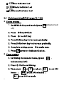
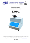
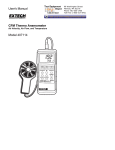
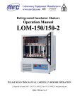
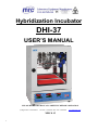
Hybridization Incubator DHI-37 USER’S MANUAL PLEASE READ THIS MANUAL CAREFULLY BEFORE OPERATION 3, Hagavish st. Israel 58817 Tel: 972 3 5595252, Fax: 972 3 5594529 MRC.8.15 1 [email protected] Contents SPECIFICATIONS ……………………………………………p3 PANEL…………………………………………………………p4 KEY DESCRIPTION……………………………………………p5 OPERATIONSDESCRIPTION…………………………………p5-p13 (1)Power…………………………………………………………………P5 (2)Temperature control………………………………………………P5-P6 2.1 Temperature setting ……………………………………………… p7 2.2 Parameter setting………………………………………………… p7-p11 LOCK Correct temperature tolerance(SHIF) auto-calculating Manual controlled (3)Speed control………………………………………………………p11 3.1 Shaking setting …………………………………………………… p11-p12 Error message and trouble shooting for temperature controller ………………………………………………………p13 MAINTENANCE & CLEANING…………………………………p14 WARRANTY CARD………………………………………………p15 2 SPECIFICATIONS DESCRIPTION MODEL SPECIFICATIONS Temp. RANGE ACCURACY DHI-37 Ambient +5℃ to 80℃ ±0.1℃ CONTROL PID Controller DISPLAY LED Digital Display SPEED 6 to50 r.p.m. ROTATION CAPACITY SPEED SHAKER TYPE CAPACITY 8 GLASS 10 to 100 r.p.m. ROTATION+Orbital Carry 6kgs ROTATION TIMER 999H / 999M / 999S SHAKER MATERIAL INSIDE OUTSIDE PLATFORM Stainless steel SUS 304 Powder painting 310x210mm INNER 350x250x425mm OVERALL 440x375x660 mm DIMENSIONS POWER VOLTAGE 3 110 V 60 Hz / 220V 60Hz PANEL& KEY DESCRIPTION 4 1. Main power switch: turn on/off main power Shaking speed switch: turn on to start shaking 2. Temp. Control: display setting and actual temperature 3. Speed control: display setting and actual speed 4. Rotisserie control: display setting and actual speed OPERATIONS DESCRIPTION After making sure voltage, please plug in 110V/ 220V socket. (1.)Power: POWER on, setting temperature SPEED on, setting speed of shaking and rotating (2.)Temperature control 1: Key for Setting/selecting: to select parameter for viewing or adjusting 2: Key for decreasing gradually: to decrease parameter. 3: Key for increasing gradually: to increase parameter 4: return/ confirm key: a. have monitor returned to PV value, display present measuring value and setting value b. clear latch alarm(when alarm condition has been 5 eliminated) c. exit manual control mode, auto-calculating mode, and calibrating mode d. clear error message or auto-calculating error message e. restart constant temperature timer f. Display output percentage on failure mode, with manual control. 5 : Display actual temperature, parameter and error message 6 : Display setting value, parameter and control output value 7 : auto-calculating LED( See the page 9) 8 : Manual controlled LED ( See the page 9) 9: Over Low LED (no this function) 10: Overheat LED (See the page 9) 11: Heating LED (See the page 10) 12: centigrade LED: LED on: means temperature is centigrade 13 : Fahrenheit LED:LED on: means temperature is Fahrenheit 6 2.1 Setting temperature 1. The temperature setting is lower than room temperature that you should turn on the Cooling switch 2. PV displays the actual temperature in chamber. 3. SV displays the setting temperature Press Press to increase temperature gradually. to decrease temperature gradually. 4. Setting temperature upon what you need. 2.2 Setting parameter 1. Press select key for 5 seconds to display , then release select key and re-press select key to modify temperature parameter. 2. SHIF setting is completed, and then press sure. 7 to make *N ote *When LOCK =NONE and no parameter is locked, user can change it freely. 1. LOCK=SET, all functions/parameters are locked. 2. LOCK=USER, all parameters are locked except S/P. 3. LOCK=ALL,all parameters are locked to prevent from being changed Modify inaccurate temperature value(SHIF) In normal condition, set SHIF to 0 , sometimes PV value is inaccurate because of detecting from different point; at this time please modify it by SHIF value. (When SHIF=0, then PV=100℃ If SHIF setting = 20.00, then PV= 120℃ If SHIF setting = −10.0 then PV= 90℃ For Example: PV(actual temperature) is 100℃ and SV(temperature setting) is also100℃, If Thermometer appears 120 ℃ or 90℃ Then set SHIF= 20 or−10 8 Auto-calculating LED: Instrument has been set the best PID value; we suggest executing auto-calculating when temperature is unstable. Enter auto-calculating: press selecting key until displayed then release selecting key. is Press selecting key again for 5 seconds to enter auto-calculating(*all parameters setting must be correct before executing auto-calculating and must be LOCK = NONE.) Manual controlled LED enter manual control mode for testing or system failure. Enter manual control mode: Keep pressing selecting key until is displayed then release; pressing selecting key about 5 seconds to enter manual control mode. ( means OP1 output percentage, means OP2 output percentage) OverHeat LED LED on: means overheat protection is on: press select key, PV displays SP2, SV displays default overheat temperature protected value: +5 ℃ 9 For example: the setting temperature is 100 ℃, and default overheat protected value is +5 ℃; when rising to 105 ℃ LED will be on and stop heating. Heating LED LED on: means heating now (*If the machine includes timer, chamber temperature start dropping after time out; at this time there is no heating though heating LED is on) (3.) Speed control of shaking 1: Power / Suspend / on: Press P/S for 5 seconds to power on/off. 2: Decrease key: Press it to decrease parameter value. 3: Increase key: Press it to increase parameter value. Press P/S to suspend working. 4: Set timing / shift-key: Press it to set timing/Press it to execute shift-key at setting RPM mode 5: Set RPM (revolutions per minute) / shift-key: Press it to set RPM/Execute shift-key function at set timing mode 6: Display actual RPM (revolutions per minute) 7: Display setting RPM or TIME 10 8: Hour indicator Led 9: Minute indicator Led 10: Second indicator Led 3.1 Shaking setting(R.P.M range:10 100) Speed setting 1. Set RPM: At Suspend mode (press P/S indicator/Led off) 2. Press Ⓢfirst, SV flash 3. Press Ⓣ to shift key 4. Press Shift-up key to increase gradually. 5. Press Shift-down key to decrease gradually. 6. Complete setting, press Ⓢto make sure, 7. Press P/S power on indicator/Led on. Timer setting 1. Set timing: At suspend mode, (press S/E , indicator/Led off ) 2. Press Ⓣ first to set timing 3. Then press hours ; ●S 11 △ or ●M ▽ to select : ●H to set 999 minutes ; to set 999 seconds to set 999 4. Press Ⓣ, SV flash 5. Press Ⓢ to shift key 6. Press △ to increase gradually 7. Press ▽ to decrease gradually 8. After setting, press Ⓣ to make sure, then go to S RPM mode automatically, user can set or make sure RPM. 9. After setting, press Ⓣ to return to set timing mode(indicator/Led on), then set timing is completed. 10. Press S/E power on, indicator/Led on 11. After power on, press Ⓢ to display RPM, or display setting time. 12. After power on, press Ⓣ to display time / time-count- backwards. (4.) Speed control of rotating (R.P.M range: 6 40) Same as (3) 12 Ⓣto TROUBLESHOOTING SITUATION CAUSE TROUBLESHOOTING 1.LED is off when power a. a. on b. Power plug is loose b. Plug in firmly or replace the socket c. c. NO power input Abnormal voltage input 2.After temperature a. Check power supply and stop using temporarily d. Fuse blowout e. Check power supply system Power cord disconnection or bad d. Check power voltage and reset connection e. Replace switch f. Replace power cord a. Waiting for temperature dropping Chamber(bath)inside actual setting,Heating temperature is higher than setting LED=(OUT1) is off temperature or cooling b. Replace b. PT platinum breakdown c. Ask for repair a. Ask for repair c. Thermometer output signal…nil 3.Heating LED is on but a. Heater disconnection temperature can not rise b. Bad heater circuit b. Ask for repair c. c. Bad control circuit d. High temperature protection-setting, e. d. Reset e. locking Ask for repair Water supply Water level of floating ball is too low(water bath) 4.Temperature keep rising a. Temperature is out of control a. Ask for repair and out of control b. Heater circuit is out of control b. Ask for repair c. P.I.D.value is not correct c. Re-calculating automatically d. S.S.R. breakdown d. Ask for repair 5.temperature tolerance is a. a. large b. P.T.D.value is not set c. Temperature is unstable or not correct Temperature setting is too close to minute b. Re-calculating AT automatically c. Add cooling system or dropping ambient temperature room temperature 13 Suspend for 30 d. circulating fan or motor cannot work d. Ask for repair e. PT platinum bad connection e. Ask for repair f. Air circulation inside is blocked f. Improve articles placement MAINTENANCE & CLEANING 1. Please follow specification to use the specified socket. Do not use old or loosened socket, and not use same socket with other machines. Instead of general extended line, please use single circuit and specified extended line to avoid overload, and to ensure operating smoothly and service life. Please make sure voltage before use; we are not responsible for any damage caused by insufficient voltage. 2. Please install it on smooth floor to avoid shaking and noise. 3. Please switch off main power and open door for 2 3 days to dry inside and parts, and to extend its service life 14 WARRANTY CARD Product Name Model Number Serial Number Date of purchase Warranty period Company Stamp (Invalid without company stamp) Condition of warranty 1. One-year warranty from the date of purchase. 2. In case damage is under normal condition of use within warranty, we will repair at no charge. 3. In case any manufacturing defect is found, it will be replaced with a new one free of charge. 4. Damage caused by card lost, human negligence, misuse or acts of God during warranty, we will repair at a reasonable charge. 5. This warranty card is invalid without company stamp, and will not be re-issued in case it is lost. 15