1
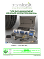
TYRE DATA MANAGEMENT
HARDWARE INSTRUCTION MANUAL
MODEL: TDP Pro Kit ( Model.105 )
Please note:
This product is manufactured to be RoHS Compliant and have
been WEEE registered.
Please read the RoHS & WEEE statements for more information.
© Trans-Logik Ltd. 2010
PL1BT-MH103UE
CONTENTS
CHAPTER 1
PRODUCT DESCRIPTION
1-1
PRODUCT OVERVIEW
1-2
PRODUCT SPECIFICATION
CHAPTER 2
THE CARRY CASE
2-1
CARRY CASE FEATURES
2-3
CARRY CASE BASIC OPERATION
CHAPTER 3
THE OTTERBOX / POCKET PC
3-1
OTTERBOX FEATURES
3-2
NOTES ON THE POCKET PC
3-3
CHARGING THE POCKET PC FROM THE CARRY CASE
CHAPTER 4
THE TYRE PROBE
4-1
TYRE PROBE FEATURES
4-2
TYRE PROBE BASIC OPERATION
4-5
CONNECTING TO THE TYRE PROBE
4-6
TYRE PROBE ENHANCED OPERATION MODES
4-7
CALIBRATION
4-8
CHARGING THE TYRE PROBE
CHAPTER 5
HELP & SUPPORT
5-1
CARE & HANDLING
5-2
TROUBLESHOOTING
5-4
SERVICE REQUIREMENT
5-5
FURTHER ASSISTANCE
5-6
RoHS & WEEE STATEMENT
APPENDICES
A
B
C
© Trans-Logik Ltd. 2010
OTTERBOX 1900 COMPATIBLE POCKET PC’S
TYRE PROBE BLUETOOTH COMMAND SET
UPDATING THE TYRE PROBE FIRMWARE
HARDWARE OPERATION MANUAL
I
PRODUCT OVERVIEW
A
B
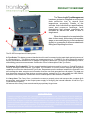
The Trans-Logik Tyre Management
hardware system is designed as a front end
data collection tool to record fleet
inspections accurately. Details of the
vehicles, their individual tyre specifications,
tread and pressure readings, fault
descriptions and relevant comments are
recorded all without the need to write a
single word.
When the inspection is completed the
data is then ready, without any intermediate
stage or secondary keying, to be transferred
directly to a computer to accommodate both
Billing and Reporting functions.
C
The PL1BT kit comprises of 3 basic parts:A. Tyre Probe: This battery powered handheld unit is used for measuring the tread depth and air pressure of
a commercial tyre. This device sends any measurements to a PocketPC (Or other Bluetooth enabled
device) via Bluetooth wireless link. An adapter is supplied to attach the Tyre Probe to a standard tyre valve,
whilst taking pressure measurements. See Section 3 for a full description of the Tyre Probe.
B. Otterbox (For PocketPC): This is a rugged handheld enclosure used for housing a PocketPC which is
used for storing the data from the Tyre Probe. The PocketPC is a touch screen computer with Bluetooth
capability to receive the data from the Tyre Probe. Dependant upon the software installed, the PocketPC can
also manage the data, accept more information from the user and generate forms & reports. This data can
then be sent to a range of other devices, such as printers, modems or Pc’s, using either the USB, RS232,
bluetooth or Wi-Fi data links. See Section 2 for a full description of the Otterbox / Pocket PC.
C. Carry Case: The Carry Case provides the means to properly store and transport the complete kit &
accessories, and includes a dual output power supply for charging the internal batteries of both the Tyre
Probe and the PocketPC.
All features of the Carry Case are enclosed by a proprietary hinged case.
Using New Kits
Upon the receipt of a new kit, it must be fully charged before use. See Section 4 for full details on
charging the Tyre Probe and PocketPC. Like most electronic measurement devices, when the
unit is fully charged, it must be calibrated before the unit is used to take measurements. The
items required are the calibration block supplied and a known air pressure. See Section 3 for full
instructions on calibrating the probe. Prior to proceeding it is imperative that both the Hardware
Manual and Software instruction manuals are read carefully.
© Trans-Logik Ltd. 2010
PRODUCT DESCRIPTION
1-1
PRODUCT SPECIFICATION
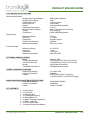
TYRE PROBE SPECIFICATIONS
General Specification:
Weight (without tyre adapter)
Weight of tyre adapter
Operational Cycle
Recharge Cycle
Battery
Operating Temperature
Wireless Communication
Range
Compliance
280g (without adapter)
190g
16 hours typical
6 hours Max
3.6V NimH Rechargeable
0 - 40 °C
Class 1 Bluetooth V2.0 (2.4GHz)
20m. in free air
RoHS, WEEE Registered
Measuring Range
Accuracy
Operations
Depth Probe Pressure
Measurement Modes
0-30mm
+/- 0.1mm
200,000+ typical
50N Max
Data, mm, inches
Measuring Range
Accuracy
Operations
Measurement Modes
10 - 150 PSI
+/- 3%
1,000,000+
Data, PSI, BAR
Depth Gauge:
Pressure Gauge:
OTTERBOX SPECIFICATIONS
Model
External Dimensions
Internal Dimensions
Weight
Compatible Pocket Pc’s
CARRY CASE SPECIFICATIONS
Input Supply Voltage
Power Consumption
Outputs
MAINS CHARGING ADAPTER SPECIFICATIONS
Input Supply Voltage
Power Consumption
Output
Otterbox 1900
165x114x56mm (6.50"x 4.50"x 2.20")
141x89x23.6mm (5.56"x 3.50"x 0.93")
340g (without PocketPC)
See Appendix A for full list
11-14VDC 2.5A
30W Max.
5V DC 2A (PocketPC Charging),
11.5VDC 500mA (Tyre Probe Charging)
100-240VAC 50/60Hz
250W Max.
12VDC 2.5A 30W
KIT CONTENTS
!
!
!
!
!
!
!
!
!
1x Carry Case
1x Tyre Probe
1x Otterbox1900
1x Tyre Adaptor Hose(J)
1x Setting Block (O)
1x Mains Charging Adapter(P)
1x Mains Cable (Q)
1x Car Charger Cable
1x Hardware Instruction Manual
© Trans-Logik Ltd. 2010
PRODUCT DESCRIPTION
1-2
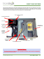
CARRY CASE FEATURES
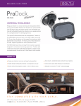
All Items that constitute the PL1BT Kit are transported (and stored when not in use) within the Carry Case.
Individual storage pockets are present for the Otterbox (with Pocket PC), Tyre Probe, Air-line and Setting
Block. A further pocket exists for the storage of loose items such as power supply cables etc. The case body
is supplied to be a robust and light means of providing a self-contained package.
DUAL OUTPUT POWER
SUPPLY
G.POWER INDICATOR
L.DC INLET
H.POWER
SWITCH
J.POCKET PC
CHARGE PLUG
O.IEC MAINS
CABLE
M.MAINS
CHARGING
POWER
SUPPLY
N.VEHICLE
CHARGING
CABLE
K.SETTING BLOCK
I.PROBE CHARGE PLUG
Important Notice:
The Carry Case is not intended to be operated ooutdoors and should be adequately
protected from the elements.
© Trans-Logik Ltd. 2010
THE CARRY CASE
2-1
CARRY CASE FEATURES
G. POWER INDICATOR - Illuminates GREEN to indicate when the “Charging Power Supply” is powered
up and switched on.
H. POWER SWITCH - Turns the “Charging Power Supply” on and off.
I.PROBE CHARGE PLUG - Plugs into the Trans-Logik Probe “charger inlet” to facilitate charging.
J. POCKET PC CHARGE PLUG - Plugs into the Pockets Pc’s “Charger Inlet” to facilitate charging.
K. SETTING BLOCK - Used for datum surfaces whilst calibrating tread depth on the Trans-Logik Probe.
L. DC INLET - 12-14VDC inlet for powering the Carry Case in built charger.
M. MAINS CHARGING POWER SUPPLY - Used to connect the Carry Case in built charger to a mains
power supply (100-240VAC 50/60Hz). This power supply can be used with any standard 3-pin IEC mains
cable to connect it to the respective mains supply.
N. VEHICLE CHARGING CABLE - Used to connect the Carry Case in built charger to a 12V vehicle
lighter socket for charging Probe and/or Pocket PC.
O. IEC MAINS CABLE - Used to physically connect the Mains Charging Power Supply to the mains
Important Notice:
When using the vehicle charging cable to power / charge the Probe or Pocket PC, it
must be connected to a 12VDC source only. You must NOT use on 24V vehicle power
sources.
When in use the Mains Charging Power Supply can get quite hot and must never be
placed on soft furnishings or flammable / heat sensitive objects.
When charging either the Probe or Pocket PC leave the Carry Case lid open. NEVER
close the Carry Case lid whilst charging.
© Trans-Logik Ltd. 2010
THE CARRY CASE
2-2
CARRY CASE BASIC OPERATION
The Carry Case has two purposes; to contain and transport all the parts of the Trans-Logik Field Kit and
to facilitate the charging of the Probe and Pocket PC. The Carry Case can be used as a charger from
two different power sources;
Charging from a standard mains supply (100VAC - 240VAC 50/60Hz):
K Plug the IEC Mains Cable (O) into the Mains Charging Power Supply (M).
K Plug the DC plug on the Mains Charging Power Supply (M) into the DC inlet (L) on the side of
the Carry Case.
K Plug the IEC mains cable (O) into the mains supply.
K Turn on the in built charger using the Power Switch (H). The Power Indicator (G) should
illuminate green.
K To charge the Probe, plug the Probe Charge Plug (I) into the Charge Port (D) on the Probe. The
Probe charge sequence should start which will be indicated by the Probe’s LED Indicator (B)
flashing red.
K To charge the Pocket PC, plug the Pocket PC Charge Plug (J) into the Pocket PC (or adapter).
The Pocket PC should now start charging. Please refer your Pocket PC user manual on the
charging of the Pocket PC.
Charging from a vehicle 12DC source (12-14VDC):
K Plug the Vehicle Charging Cable (N) into the DC Inlet (L) on the side of the carry case.
K Plug the Vehicle Charging Cable (N) into a suitable 12V cigarette lighter socket on the vehicle
and ensure it is powered up. (Some vehicles may need the ignition to be turned on to power up
the lighter socket).
K Turn on the in built charger using the Power Switch (H). The Power Indicator (G) should
illuminate green.
K To charge the Probe, plug the Probe Charge Plug (I) into the Charge Port (D) on the Probe. The
Probe charge sequence should start which will be indicated by the Probe’s LED Indicator (B)
flashing red.
K To charge the Pocket PC, plug the Pocket PC Charge Plug (J) into the Pocket PC (or adapter).
The Pocket PC should now start charging. Please refer your Pocket PC user manual on the
charging of the Pocket PC.
For more detailed information on charging the Probe please refer to section 4-8
“Charging The Probe”.
© Trans-Logik Ltd. 2010
THE CARRY CASE
2-3
OTTERBOX FEATURES
FLIP-UP HARD SCREEN
PROTECTOR
REMOVEABLE TOP
SEALED SCREEN
MEMBRANE
QUICK RELEASE CLASPS
STYLUS HOLDER
QUICK ACCESS RUBBER
DOOR
The OtterBox 1900 Pocket PC / PDA Case
This is a versatile, rugged, expandable PDA case which houses the PocketPC used for collecting and
organising the data from the Tyre Probe.
It’s main features include;
K Universal fit for newer smaller form-factor PDAs Waterproof, crushproof, drop- proof ergonomic
design
K Flexible, fully sealed interactive screen membrane
K Quick access to CF and SD slots through the top of the case
K Quick access to PDA connection through the bottom of the case
K Adjustable neoprene handstrap
K External stylus holder
K Flip-up hard screen cover
K Headphone/headset access
Please see Otterbox Instruction Leaflet for fitting the Pocket PC / PDA
© Trans-Logik Ltd. 2010
THE OTTERBOX / POCKET PC
3-1
NOTES ON THE POCKET PC
The Trans-Logik Hardware Kit was designed for, and is recommended for use with Hewlett Packard, Dell and
Fujitsu-Siemens range of Pocket PC’s. However other products can be used.
Below are some notes which may help when selecting or using a compatible alternative to the HP iPaq
range:K The Tyre Probe uses a standard Bluetooth V1.1 connection it can therefore communicate with
almost any other Bluetooth enabled Pocket PC, PDA , Notebook PC or Desktop PC.
K The Otterbox is compatible with the majority of Pocket PC’s & PDA’s currently on the market. Please
see Appendix A for a list of compatible devices.
K The PPC output of the carry case charger is 5VDC @ 2Amax which is the required supply for
charging and powering the HP iPaq, Dell and many other models of Pocket PC / PDA. The charger
output also terminates with a 1.3mm DC Jack Plug, which is standard for plugging directly into Hp
and Dell’s range of Pocket PC cables & accessories.
K Pocket PC / PDA requirements:K The Pocket PC / PDA has Bluetooth V1.1 (or Better) connectivity.
K The Pocket PC / PDA has the correct hardware specification and operating system to run the
required software.
K The Pocket PC / PDA physically fits into the Otterbox. (See Appendix A for a list of compatible
models)
K The Pocket PC / PDA requires 5VDC @ 2Amax to charge and power the device.
K A suitable adaptor may be required for plugging into the PPC charger cable. (Contact TransLogik for more information)
K If using software supplied by Trans-Logik please check that the software is compatible with the
chosen PocketPC.
Useful Pocket PC Operating Tips
! When entering data, if there is an 'Accept’, ‘ Save’ or ‘OK' button available on the
Pocket PC, click on it to ensure any input data is saved.
! Never use a sharp object to operate the Touch Screen as it may puncture the display
and cause failure.
! Using a pen on the touch screen will not damage the screen, but it does tend to leave
messy ink marks upon it which may obscure the display.
! Even when the Pocket PC is turned off it is draining the battery/s and therefore is
good practice to return the Pocket PC to the Carry Case and place on charge when not in
use.
! When the Pocket PC battery is low it will power itself down to protect the integrety of
the memory.
! Never let the Pocket PC battery drain completely. If this happens the installed
software will be lost and the Pocket PC will return to its original ‘out of box’ condition. In
this instance refer to the software manual for instructions on ‘Recovering The Software’.
© Trans-Logik Ltd. 2010
THE OTTERBOX / POCKET PC
3-2
CHARGING THE POCKET PC FROM THE CARRY CASE
CHARGING THE POCKET PC
Pocket PC’s are usually supplied with a charger / power supply to re-charge the batteries of the
device. However, for convenience, the Carry Case also includes a charger / power supply to re-charge the
Pocket PC. This can be used instead of the supplied charging device on compatible Pocket Pc’s.
To re-charge the Pocket PC from the Carry Case:-
K Ensure the Carry Case Charger is plugged into a suitable supply and turned ON and the ‘Power’
indicator (ML1) is illuminated.
K Plug the ‘PPC Charge’ Cable (K) into the relavent cable or adaptor for the Pocket PC and plug the
adaptor into the port on the Pocket PC. After a short period of time, the Charge Indicator on the
Pocket PC should start to flash. This is indicating that it is fast charging the internal battery of the
Pocket PC.
K The Pocket PC should indicate when the charge has finished as described in the instruction manual
for the Pocket PC used.
Important Notice:
! Please carefully read the instructions on operating and handling the Pocket PC
that were supplied with the Pocket PC.
! The Pocket PC will charge more quickly if it is turned off.
! Depending upon the installed software and upon the model of Pocket PC, the
Pocket PC may automatically power up as it is plugged into the charger. If this does
happen, simply press the Power Button on the Pocket PC to turn it off.
© Trans-Logik Ltd. 2010
THE OTTERBOX / POCKET PC
3-3
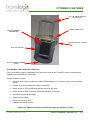
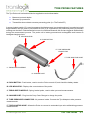
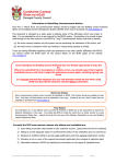
TYRE PROBE FEATURES
The Tyre Probe unit is a hand held device supplied to conduct three tasks:K Measure tyre tread depths.
K Measure tyre pressures.
K Transmit the above data to a remote processing point. (I.e. The Pocket PC)
A sprung loaded needle (C) is used to measure the displacement (tyre tread depth) as it is pushed at a right
angle between the tyre tread. A part flexible air-line (F) is connected to the probe body and tyre pressure
readings can be taken. Data transmissions are via a wireless Bluetooth link and are triggered automatically
during the measurement process. The probe unit is battery powered and rechargeable and houses an
intelligent charging circuit.
B. LED INDICATOR
A. PUSH BUTTON
E. TYRE PRESSURE
CONNECTOR
F. TYRE ADAPTOR HOSE
C. TREAD DEPTH NEEDLE
D. CHARGE PORT
A. PUSH BUTTON - Push-button, used to turn the Probe on and off, and check the battery status.
B. LED INDICATOR - Displays the current status of the probe.
C. TREAD DEPTH NEEDLE - Spring loaded probe, used to take tyre tread measurements.
D. CHARGE PORT - Plug into the Carry Case Charger to charge the probe.
E. TYRE PRESSURE CONNECTOR - Air pressure intake. Connect the Tyre Adaptor to take pressure
measurements.
F. TYRE ADAPTOR HOSE - Allows the Probe to connect to a standard tyre valve whilst taking pressure
measurements.
© Trans-Logik Ltd. 2010
THE TYRE PROBE
4-1
TYRE PROBE BASIC OPERATION
OPERATION OF THE LED INDICATOR
The probe incorporates an LED Indicator (B) to show the operation and status of the probe.
The following table describes the operation of the LED indicator (B):COLOUR
RED
RED FLASHING
GREEN
GREEN FLASHING
AMBER
AMBER FLASHING
POWER OFF
Conditioning Charge
Fast Charge
POWER ON
Initialising Probe(Upon powerup)
Battery Low
Probe Ready
Probe Ready & Battery Low
-
BATTERY STATUS MODE*
Battery Low, requires charging
Battery Good
-
TURNING ON THE TYRE PROBE
The Tyre Probe is operated using the ‘Push Button’ (A). To turn on the Tyre Probe:K Press and hold ‘Push Button’ (A) until the ‘LED Indicator’ (B) illuminates RED. This usually takes 2-3
seconds.
K The Tyre Probe is now powering up and initialising.
K After about 7-10 seconds the ‘LED Indicator’ should change to GREEN.
K The Tyre Probe is now powered up and ready to use.
TURNING OFF THE TYRE PROBE
The Tyre Probe is operated using the ‘Push Button’ (A). To turn off the Tyre Probe:K Press and hold ‘Push Button’ (A) until the ‘LED Indicator’ (B) extinguishes. This usually takes 2-3
seconds.
K The Tyre Probe is now powered down and in “stand-by” mode.
If the Tyre Probe is plugged into the charger when it is turned off the ‘LED Indicator’
(B) will not extinguish if the battery is charging. Instead the’LED Indicator’ (B) will
flash repeatedly to display the charging mode. The Tyre Probe will automatically turn
off (or go into stand-by) once the charge cycle is complete.
CHECKING THE BATTERY STATUS* (Feature only available on 105 models)
K The Tyre Probe is operated using the ‘Push Button’ (A). To turn on the Tyre Probe:K With the Tyre Probe in OFF (or stand-by) mode, press and hold ‘Push Button’ (A) for 1 second.
K Release ‘Push Button’ (A). The LED Indicator should illuminate GREEN for approximately 1 second
and then it will display the battery status for a further 2-3 seconds.
K If GREEN, the probe battery is charged. If RED the probe battery is low and requires charging.
Do not use the Tyre Probe with a low battery. If the Tyre Probe is operated with a low
battery it may incorectly measure the tread depth and pressure, or you may
experience Bluetooth connection problems.
© Trans-Logik Ltd. 2010
THE TYRE PROBE
4-2
TYRE PROBE BASIC OPERATION
TYRE PROBE MEASUREMENT MODES
The Tyre Probe can take tread and pressure measurements in 2 ways:K Automatic - The Tyre Probe automatically sends measurements after it senses a change in either
tread depth or air pressure and when it senses the tread or pressure measurement stabilise.
K Manual - Tread and pressure measurements can be taken anytime by sending a “T” or “P”
command via the Bluetooth to the probe. When the Tyre Probe receives this command it will take
the relevant measurement and transmit the data back. (See Appendix A - Bluetooth Command Set
for further information )
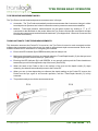
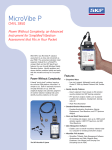
TAKING AUTOMATIC TYRE TREAD MEASUREMENTS
This instruction assumes the Pocket PC is turned on, the Tyre Probe is turned on and connected and the
software has progressed to the point where it is ready to accept tread depth measurements. Refer to the
software manual for full instructions on navigating the software.
K Ensure the LED indicator (B) is GREEN and the probe is ready to use.
K Making sure the tread is free from mud and grit, place the ‘Tread Depth Needle’ (C) into the tyre tread
at a right angle to the surface of the tyre. {See FIG.A}
K Ensuring the LED indicator (B) is still GREEN, in one smooth motion push the Probe head down
toward the tyre until it is flat against the top of the tread. {See FIG.B}
K When the head of the Probe is flat on the surface of the tyre and the depth needle (C) stops
retracting the data will automatically be sent to the Pocket PC.
K When you see (or hear depending on software) the depth reading on the Pocket PC remove the
Probe from the tyre, again in one smooth operation, until the ‘Tread Depth Needle’ (C) is fully
extended.
K The probe is ready to use for the next measurement.
FIG.A
© Trans-Logik Ltd. 2010
FIG.B
THE TYRE PROBE
4-3
TYRE PROBE BASIC OPERATION
TAKING AUTOMATIC TYRE PRESSURE MEASUREMENTS
This instruction assumes the Pocket PC is turned on, the Tyre Probe is turned on and connected and the
software has progressed to the point where it is ready to accept tread depth measurements.
Refer to the software manual for full instructions on navigating the software
K Ensure the LED indicator (B) is GREEN and the probe is ready to use.
K Connect the ‘Tyre Adaptor Hose’ (F) to the ‘Tyre Pressure Connector’ (E) on the Probe.
K In one smooth operation push the ‘Tyre Adaptor Hose’ (F) on to the tyre valve until air is released into
the Probe. When the pressure in the hose stabilises the data will automatically be sent to the Pocket
PC.
K Hold the ‘Tyre Adaptor Hose’ (F) on the valve until you see (or hear depending on software) the
measurement is displayed on the Pocket PC. {See FIG.C}
K At this point, again in one smooth operation, remove the ‘Tyre Adaptor Hose’ (F) from the tyre valve.
K The probe is ready to use for the next measurement.
FIG.C
Useful Operating Tips
! When taking Depth measurements, after a reading has been taken allow the probe
needle to fully return before taking the next measurement.
! When connecting the Tyre Adaptor Hose (F), ensure there is no obstruction in the
Air Connector.
! When taking pressure measurements, after a reading has been taken, remove the air
pressure as quickly and smoothly as possible.
! When fitting or removing the tyre adapter, ensure the probe is turned off.
! When not measuring pressure remove the tyre adapter Hose (F). The probe device is
easier to handle for depth measurements if the tyre adapter is removed.
! If the Probe ever returns an error or loses its zero position (Unit fails to take automatic
measurements) due to improper operation, simply turn the probe off and then on again
using the Push Button (A) to reset the device.
© Trans-Logik Ltd. 2010
THE TYRE PROBE
4-4
CONNECTING TO THE TYRE PROBE
The Tyre Probe communicates to your Pocket PC or other Bluetooth enabled device using a
standard Bluetooth V1.1 wireless connection. The Probe utilizes the standard virtual serial port protocol to
send and receive standard ASCII format serial data, which enables it to operate in a very similar manner to
many other serial device such as modems etc. Different Pocket Pc’s or PDA’s all have different software for
managing its Bluetooth connections, however using a standard Bluetooth protocol means that every type of
Pocket PC has to function in a similar way to connect to the devices. The basic steps for connecting to the
probe are as follows;
K Search & detect the Bluetooth connection of the probe - Most Bluetooth applications have a
method of searching for the available Bluetooth devices. The Tyre Probe usually shows up during
the search with the name “Pneu Logic Probe - Dxxxxxx”.
K Pair with the probe - Most Bluetooth applications will let you pair with the probe. Pairing is simply a
way of indicating to the Pocket PC which device(s) you want to connect to. Also during the pairing
process the Bluetooth security measures must be passed through and the software may ask for a
passkey. Bluetooth uses a simple 4 digit passkey to authenticate the connection. The default
passkey for all probes is “1234”.
K Discover the available service - The probe uses the standard serial port protocol which often has
to be selected from the service list. This service is called “Tyre Probe” and must be selected before
the device can assign the probe its COM port number. When the serial port service has been
selected a COM port number will be assigned to the probe.
K Connect to the serial port and communicate - Standard serial communications routines can be
used to connect to the assigned COM port. Communication is performed using standard ASCII text
format. The software application on your Pocket PC should automatically handle any
communications with the probe giving the operator a user friendly interface to enable them to use
the probe with ease. However other COM’s applications can also be used to communicate with the
probe like Hyperterminal which is supplied with most releases of Microsoft Windows on desktop or
laptop Pc’s. The list of commands can be found in Appendix B.
Useful Connection Settings:
COM Port
Bluetooth Passkey
Baud Rate
Data bits
Parity
Stop Bits
Start Bits
Assigned by Bluetooth Manager Application
1234
9600 bps
8
None
1
1
For more information on enhanced operation, serial commands and how to use
them please refer to the Bluetooth Command Set (Appendix B).
© Trans-Logik Ltd. 2010
THE TYRE PROBE
4-5
TYRE PROBE ENHANCED OPERATION MODES
For enhanced operation the Tyre Probe can function in many different modes which allows the Probe
to report its measurements in different ways. These modes are:Tread Depth Modes:
K Actual - When set to “actual” mode the probe returns the raw measurement data from the
embedded analogue to digital converter. This data is returned in decimal format as ASCII text. This
data is in the range 0 to 1024. E.g. T1010.
K Millimeter Measurement Mode -When set to “mm” mode the probe returns the tread
measurement in actual millimeters.This data is returned in ASCII text format. This data is typically in
the range 0 to 28mm.This mode will only function correctly if the probe has been calibrated and it
contains tread measurement calibration data in its internal memory. E.g. T19.85
K Inches Measurement Mode - When set to “Inch” mode the probe returns the tread measurement in
actual imperial inches. This data is returned in ASCII text format. This data is typically in the range 0 1.10.This mode will only function correctly if the probe has been calibrated and it contains tread
measurement calibration data in its internal memory. E.g. T0.76
Pressure Modes:
K Actual - When set to “actual” mode the probe returns the raw measurement data from the
embedded analogue to digital converter. This data is returned in decimal format as ASCII text. This
data is in the range 0 to 1024. E.g. P1010.
K BAR Measurement Mode - When set to “BAR” mode the probe returns the pressure measurement
in actual BAR.. This data is returned in ASCII text format. This data is typically in the range 0 10.This mode will only function correctly if the probe has been calibrated and it contains tread
measurement calibration data in its internal memory. E.g. P6.45
K PSI Measurement Mode -When set to “PSI” mode the probe returns the pressure measurement in
actual PSI. This data is returned in ASCII text format. This data is typically in the range 0 to
150PSI.This mode will only function correctly if the probe has been calibrated and it contains tread
measurement calibration data in its internal memory. E.g. P99.55
Other Modes:
K Click Mode - With this feature enabled when you are measuring tyre tread and pressure everytime
the push button on the top of the probe is pressed for between 0.25 and 3 seconds the probe will
send a command back to the Pocket PC to let it know the button has been pressed. This command
can be used in the Pocket PC (If software supports click feature) to automatically switch between
tyres and/or vehicles. Please note this feature is only available to 103 & 104 models that have
version 2.08 firmware or better, but is a standard feature on model 105 probes.
K Idle Timeout Mode - To save battery power if the probe is inactive for a set period of time it will
automatically shut itself off. This set period can be set between 0 and 255 minutes. Setting this value
to 0 will disable the timeout mode.
For more information on enhanced operation modes and how to use them please
refer to the Bluetooth Command Set (Appendix B).
© Trans-Logik Ltd. 2010
THE TYRE PROBE
4-6
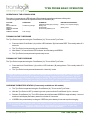
CALIBRATION
To use the probe in either mm, inches, PSI or BAR measurement modes the probe must first be
calibrated. To calibrate the probe must be given 4 calibration valuies. These 4 values are:K Tread measurement at 0mm (X3 Value)
K Tread Measurement at 16mm (X4 Value)
K Pressure measurement at 0 PSI (X5 Value)
K Pressure measurement at 100 PSI (X6 Value)
The application software on the Pocket PC or other Bluetooth device you are using should include a small
calibration routine to allow these values to be set. Every application is different, but the general calibration
procedure must be similar. The description below describes how a typical calibration procedure can be
achieved.
Calibrating tread:
K Using the flat end of the calibration block (supplied with kit) set the tread depth needle to 0mm
by pushing the nose of the probe fully flat upon the block.
K Click “Calibrate 0mm” or similar button on the Pocket PC application. (Click OK on dialog box
appropriate)
K Wait a couple of seconds then release the tread depth needle back to its fully extended position.
K Using the 16mm end of the calibration block (supplied with kit) set the tread depth needle to
16mm by pushing the nose of the probe fully flat upon the top of the block and the needle inside
the 16mm deep hole.
K Click “Calibrate 16mm” or similar button on the Pocket PC application. (Click OK on dialog box if
appropriate)
K Wait a couple of seconds then release the tread depth needle back to its fully extended position.
Calibrating pressure:
K Using atmospheric pressure as 0PSI set the pressure to 0PSI by ensuring the pressure inlet is
vented to atmosphere and there is no pressure applied to the probe.
K Click “Calibrate 0PSI” or similar button on the Pocket PC application. (Click OK on dialog box if
appropriate)
K Using a known 100PSI pressure set the pressure value by applying the 100 PSI air pressure to
the inlet of the probe.
K Click “Calibrate 100PSI” or similar button on the Pocket PC application. (Click OK on dialog box
if appropriate)
K Wait a couple of seconds then release the air pressure and allow the inlet to vent to atmosphere.
Notes On Calibration:
Practice on operating the probe is needed to obtain accurate readings. As you practice
you will find your readings become more consistent. The more accurate the known
100PSI air pressure the more accurate the calibration.
© Trans-Logik Ltd. 2010
THE TYRE PROBE
4-7
CHARGING THE TYRE PROBE
CHARGING THE PROBE
The Tyre Probe contains an intelligent charger circuit to help maintain the batteries. Charging of the
Tyre Probe is performed using the charger power supply inside the Carry Case. To re-charge the internal
batteries of the Tyre Probe:K Ensure the Carry Case Charger is plugged in to a suitable supply and turned ON and the ‘Power’
indicator (ML1) is illuminated.
K Ensure the Probe is turned OFF.
K Plug the ‘Probe Charge Cable’ (L) into the ‘Charge Port’ (H) on the Probe. The ‘Probe Indicator’
(ML2) should illuminate FLASHING RED to indicate the Probe is in conditioning charge mode.
K After 2 to 10 minutes the ‘Probe Indicator’ should change to FLASHING AMBER to indicate it is in
fast charge mode.
K When the ‘Probe Indicator’ (ML2) goes out the probe is fully charged.
Important Notice:
! The charging circuit is ‘Intelligent’, so if the ‘Probe Indicator’ (ML2) does not
illuminate when it is first plugged in, the battery is fully charged.
! If the Probe’s battery has been allowed to go totally flat for an extended period of
time this can cause the battery to reject the charge and terminate early. In this
situation when the charging stops place the probe straight back on charge again.
Keep putting the probe on charge repeatedly until it has had a total of 4 hours
charge time. The battery should recover after 2-3 charge / discharge cycles.
! If the ‘Probe Indicator’ remains in conditioning charge mode (FLASHING RED)
for longer than 20 minutes this could mean the following;
! The environmental conditions are not correct. (I.e. Too cold or too hot)
! The intelligent charger circuit has got out of sequence.
! There is a fault with the probe or battery.
If this occurs first try unplugging the ‘Probe Charge Cable’ (L) from the ‘Charge
Port’ (H) on the Probe, waiting for 20 seconds and plugging back in again. If this
has no effect try charging in a more acceptable environment.
© Trans-Logik Ltd. 2010
THE TYRE PROBE
4-8
CARE & HANDLING
The Trans-Logik Tyre Data Management Kit has been designed for rugged industrial use. However, handling
the equipment with care will increase its accuracy, usability and life span. Some pointers for particular
attention are as follows :K Read the operating instructions fully before operating the equipment.
K Follow the operating instructions carefully whilst operating the equipment.
K Keep the Probe as clean and dry as possible, especially around the ‘Tyre Adaptor Hose’, ‘Tread
Depth Needle’ and ‘Charge Port’.
K Never use the Probe’s ‘Tread Depth Needle’ as a pry bar or lever.
K Care should be taken during inclement weather conditions to protect the Pocket PC as much as
possible from the elements.
K Keep the Pocket PC out of extreme temperatures and direct sunlight.
K In extreme temperatures try to keep the Pocket PC in a more suitable environment such as in an
office or cab of a lorry etc.
K Never use any sharp pointed device on the Pocket PC ‘Touch Screen’ display.
K Never operate the Docking Station outdoors.
K If the equipment is not being used ensure it gets a full charge at least once a week.
K Always use the correct Trans-Logik charging devices to charge the equipment and never use any
type of charger or power supply off any other equipment or supplier.
K Always ensure the plugs are securely inserted into the equipment whilst charging.
© Trans-Logik Ltd. 2010
HELP & SUPPORT
5-1
TROUBLESHOOTING
If any problems are encountered first check you are performing the operation correctly as per instructions.
Read all instructions carefully to ensure that the correct procedures are implemented.
If problems are still encountered check through the following possibilities.
K THE POCKET PC BACKLIGHT WILL NOT ILLUMINATE.
POSSIBLE CAUSE: The backlight has been disabled.
REMEDY: Whilst the Pocket PC is powered up, hold down the Power Button on the Pocket PC for 2
seconds to enable the backlight. Note: This is only for the HP iPaq range of Pocket Pc’s.
K THE PROBE AND/OR POCKET PC WILL NOT CHARGE.
POSSIBLE CAUSE: There is no power to the charger or the charger is not turned on.
REMEDY: Please check that the switch on the charger PSU is turned on and that the LED is illuminated
green.
REMEDY: Please check external power supply / cigarette charger is plugged correctly into the side of the
charger PSU and that the mains supply (if applicable) is turned on. If using the cigarette lighter socket on
your vehicle ensure it is in operation as some only function with the vehicle ignition switch turned on.
REMEDY: The external power / cigarette lighter cable supply plug MUST be securely inserted into the
charger PSU socket until the plug locates at the rear of the socket. On new units the plug can be a little
stiff or tight and may require a little extra force to ensure the plug is located correctly.
REMEDY: Check the fuse in the mains cable of the external power supply.
K THE PROBE BATTERY DOES NOT CHARGE CORRECTLY AND THE LED INDICATOR
REMAINS FLASHING RED.
POSSIBLE CAUSE: The Probes integrated charger circuit will only charge the battery if the correct
environmental criteria are met. The charger will refuse to charge the battery if it is too cold, too warm, has
been run too flat or if there is a fault with the battery.
REMEDY: If the probe is in a particularly hot or cold environment please attempt charging in a more
suitable location. Eg. The office.
REMEDY: If the battery was run extremely flat the charger circuit needs to condition the battery before
attempting a full charge. In this situation you should leave the probe in conditioning mode (LED indicator
flashing RED) for approx 20mins then disconnect the charger supply and re-connect to reset the
charging cycle. The probe should now charge correctly.
REMEDY: Keep your probe updated with the latest firmware. Newer firmware releases have enhanced
functionality and is constantly being improved to make the battery management more efficient.
POSSIBLE CAUSE: If the Probe has not been serviced for more than 12 months it is possible the
internal battery has become worn.
REMEDY: The Probe will require service.
K THE PROBE BATTERY DOES NOT CHARGE CORRECTLY AND THE CHARGE KEEPS
TERMINATING EARLY OR THE PROBE SEEMS UNABLE TO RETAIN ITS CHARGE FOR ANY
REASONABLE LENGTH OF TIME.
POSSIBLE CAUSE: If the Probe’s battery has been allowed to go totally flat for an extended amount of
time this can cause the battery to reject the charge and terminate early.
REMEDY: When the charge terminates place the probe back on charge again. Keep repeating this until
the battery has had a total of 4 hours of charge time. The battery should recover after 2-3 charge /
discharge cycles.
POSSIBLE CAUSE: If the Probe has not been serviced for more than 12 months it is possible the
internal battery has become worn.
REMEDY: The Probe will require service.
© Trans-Logik Ltd. 2010
HELP & SUPPORT
5-2
TROUBLESHOOTING
K THE PROBE WILL NOT TURN ON.
POSSIBLE CAUSE: The Probe requires its internal batteries charging.
REMEDY: Place the Probe on charge.
POSSIBLE CAUSE: The Probe push button was not held down for 4 seconds.
REMEDY: To turn the Probe on and off the push button on the top must be held down for 4 seconds. This
feature is to help prevent accidentally turning the probe on/off.
K THE PROBE WILL NOT TURN ON AND WHEN I PLACE ON CHARGE THE LED LIGHT
ILLUMINATES CONSTANT GREEN.
POSSIBLE CAUSE: The Probes internal firmware has become corrupt.
REMEDY: The most common cause of the firmware becoming corrupt is an incorrect or failed firmware
upgrade attempt. If this is the case then the probe will remain in “upgrade” mode until a successful
upgrade is completed. In which case check that you have the correct upgrade software, the correct
revision of firmware, plug into the charger and try again.
REMEDY: If the probe cannot be recovered by a firmware upgrade or it has become corrupt for any other
reason the probe must be returned for service.
K THE PROBE TAKES INCONSISTENT, INACCURATE OR WILL NOT TAKE TREAD
MEASUREMENTS.
POSSIBLE CAUSE: The Probe requires calibration.
REMEDY: Re-calibrate the probe.
POSSIBLE CAUSE: If the Probe has not been serviced for over 12 months then the tread pot assembly
may be worn.
REMEDY: .The probe must be returned for service.
© Trans-Logik Ltd. 2010
HELP & SUPPORT
5-3
SERVICE REQUIREMENT
The Trans-Logik Probe contains serviceable and consumable parts and Trans-Logik recommend that all
PL1BT series Probes are serviced every 12 months of use. The service includes;
1.
2.
3.
4.
5.
6.
7.
Replacement of Tread Pot Assembly.
Replacement of Battery Pack.
Replacement of seals and grommets.
Cleaning the internal parts & electronics.
Checking for and removing any blockages of the pressure assembly.
Upgrade to latest firmware revision if required.
Re-calibration and re-testing.
Trans-Logik will supply a 12 month parts & labour warranty for any parts that are replaced.
The unit will also be checked over for any other damage or wear and repairs will be undertaken if necessary.
Any parts replaced not covered by the service will be charged in addition to the service cost.
Any service or repair will only be undertaken by Trans-Logik or by a Trans-Logik authorised service agent.
For more information on the Trans-Logik service contract or to get your Trans-Logik product serviced please
contact either Trans-Logik or your I.T. Managment / Department.
© Trans-Logik Ltd. 2010
HELP & SUPPORT
5-4
FURTHER ASSISTANCE
If you require assistance or have any queries please contact your administrator:
For further information you can:K Check out our website at www.trans-logik.com
K E-mail your query to [email protected]
K Telephone our customer support line +44(0) 1869 238380
Tel: +44(0) 1869 238380
Fax: +44(0) 1869 238381
[email protected]
© Trans-Logik Ltd. 2010
HELP & SUPPORT
5-5
RoHS & WEEE STATEMENT
RoHS, also known as Lead-Free, stands for Restriction of Hazardous Substances. RoHS Directive
2002/95/EC restricts the use of six hazardous materials found in electrical and electronic products. The
substances banned under RoHS are lead (Pb), mercury (Hg), cadmium (Cd), hexavalent chromium (CrVI),
polybrominated biphenyls (PBB) and polybrominated diphenyl ethers (PBDE). All applicable products in the
EU market after July 1, 2006 must pass RoHS compliance.
This Trans-Logik product complies with the requirements of the RoHS directive for all banned
substances.
Directive 9002/96/EC Waste Electrical and Electronic Equipment (the "WEEE Directive") which was
introduced into European Law on 13th February 2003 encourages the proper repair, upgrading, reuse, or
disassembly and recycling of certain categories of electronic equipment.
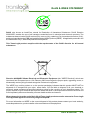
The WEEE logo on this product or on the product packaging indicates that this product MUST NOT be
disposed of or dumped with your other waste items. You are liable to dispose of all your electrical or
electronic waste equipment at specified collection points for the recycling of such hazardous waste. The
proper disposal of your electrical and electronic waste will allow us to help conserve natural resources and
more importantly will ensure the safety of human health and the environment.
When deemed to be at the end of their life all Trans-Logik products must be returned to Trans-Logik
or an appointed agent for correct recycling and disposal.
For more information on WEEE or the correct disposal of this product please contact your local authority,
waste disposal service, product retailer or the manufacturer of the equipment.
© Trans-Logik Ltd. 2010
HELP & SUPPORT
5-6
OTTERBOX 1900 COMPATIBILE POCKET PC’S
Although Trans-Logik recommend using the HP iPaq range of Pocket Pc’s with the PL1BT Kit the Otterbox is
compatible with a wide range of other Pocket Pc’s. The following table lists other compatible models:
BRAND
MODEL
ACCESSORY
FIT IN 1900
TESTED
Acer
n10
n20 and n20w
n30
Y
Y
Y
N
N
N
Asus
MyPal 600
MyPal 620/620BT
Y
Y
N
N
Y
Y
Y
Y
Y
N
N
N
N
N
Audiovox 2032 & 2032SP
1032C
PPC4100
PPC5050BM
PPC6600/01/00WOC
NOTES
Antenna may be a problem in the standard case and might require a medium POD to fit
Antenna may be a problem in the standard case and might require a medium POD to fit
Antenna may be a problem in the standard case and might require a medium POD to fit
Unit cannot be slid open in case and therefore the keyboard will not be usable in the case
Dell
Axim X3/X3i
Axim X30
Axim X50/X50v
Y
Y
Y
Y
Y
Y
Fujitsu
Loox 400 Series
Loox 600 Series
Loox 700 Series
Y
Maybe
Y
N
N
N
iQue M5
Y
N
iQue 3200
iQue 3600
Y
Y
N
Y
iPAQ 1700 Series
iPAQ 1900 Series
iPAQ 2100 Series
iPAQ 2200 Series
iPAQ 2400 Series
iPAQ 2400 Series
iPAQ 2700 Series
iPAQ 3100 Series
iPAQ 3700 Series
iPAQ 4100 Series
iPAQ 4700 Series
iPAQ 5100 Series
iPAQ 5500 Series
iPAQ 6300 Series
Y
Y
Y
Y
Y
Y
Y
Y
Y
Y
Y
Y
Y
Y
Y
Y
Y
Y
Y
Y
Y
Y
Y
Y
Y
Y
Y
Y
Y
Y
Y
N
N
N
Antenna cannot be unfolded because it does not fold fully flat
Y
N
Should fit, but we are unsure about the antenna situation on this model
XDA
XDAII
Y
N
N
Y
PDA is too thick
Zire 21
Zire 31
Zire 72
Tungsten E
Tungsten T3
Tungsten T5
Tungsten C
Treo 600 & 650
Y
Y
Y
Y
Y
Y
N
Y
N
N
N
N
N
N
N
Y
N
N
Garmin
HP
Mitac
SD/CF WiFi Cards
Mio168
Mio336
Mio558
Navman PiN
O2
Palm
Panasonic P1
Qtek
2020
Y
N
Tapway
Zodiac
Y
N
Toshiba
e400
e800
Y
Y
N
N
© Trans-Logik Ltd. 2010
Not tested and very close on length. May require medium POD lid to clear antenna
In order to have antenna unfolded, a large POD will be required
Based on dimensions the thickness will be a tight fit, needs testing to know for sure
In order to have antenna unfolded, a large POD will be required
In order to have antenna unfolded, a large POD will be required
Fits in the 1900 case with the standard POD lid that is included with the case
We highly recommend using a 4700 custom screen (see accessories) for best functionality
Includes 5555 model - a sleeve cannot be used in conjunction with this case (see 3600)
Keyboard cannot be used with case
Should fit fine when closed, but we are unsure about it when open
Keyboard is too wide for the screen opening
Should fit dimensionally, but button access may be questionable in landscape format
APPENDIX A
TYRE PROBE BLUETOOTH COMMAND SET
K Introduction
This appendix details the commands that can be transmitted/received from the Trans-Logik Bluetooth
enabled tyre and pressure measuring probe, hereafter called the Tyre Probe.
K Hardware
The Probe contains a TDK Bluetooth transceiver that presents itself to a PC as a serial device. The serial
device can be connected using the following settings
Baud Rate
Data Bits
Parity
Start Bits
Stop Bits
9600
8
None
1
1
K Bluetooth Connection
The Probe can connect to any Bluetooth enabled PC or Pocket PC. The Probe device will display on the PC
as “Pneu Logic Probe Dnnnnnn” where nnnnnn is a six character string. When selected the service supplied
by the Probe device is “Tyre Probe on Pneu Logic Probe Dnnnnnn” this is a serial port and can connect to any
serial terminal program when a pairing is made. When the Probe is paired with the PC a PIN may be asked
for, this has been factory set to “1234”.
The data from the probe is transmitted via the bluetooth in 10 Bit ASCII Text Format and allows the full range
of the A/D module to be utilised and for the data to be viewed in a terminal program as ASCII data, the data is
transmitted in the following format:Command
Thousands
Hundreds
Tens
Units
Terminator
© Trans-Logik Ltd. 2010
<varies>
decimal number 0 - 9 (30 - 39 hex)
decimal number 0 - 9 (30 - 39 hex)
decimal number 0 - 9 (30 - 39 hex)
decimal number 0 - 9 (30 - 39 hex)
<cr> (0D Hex)
APPENDIX B-1
TYRE PROBE BLUETOOTH COMMAND SET
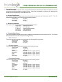
K Normal Operation
The Probe is simple to operate, when a connection has been made the tread depth and pressure of a tyre
can be sent by taking samples using the Probe. When the tread depth or pressure has stabilised the
reading is sent automatically via the Bluetooth link.
K Receive Data Format
This section details the data format used to transmit commands to the Probe from the PC. The PC
transmits commands to the Probe using the following format:START byte
A2 (hex)
Command
varies
STOP byte
A7 (hex)
K Receive Commands
The commands currently accepted by the Probe are as follows:W (57 hex)
Wakeup/Shut down
A (41 hex)
Acknowledge
F (46 hex)
Negative Acknowledge
L (4C hex)
Learn the RF ID
Q (51 hex)
Query the RF ID
K Transmit Data Format
This section details the data format used to transmit commands from the Probe to the PC. The Probe
transmits it's data to the PC using the following formats.
! ACK Command
The probe may acknowledge a command with the following ACK command:START byte
A2 (hex)
Command
A (41 hex)
STOP byte
A7 (hex)
! Pressure Reading
The Probe will transmit a pressure reading in the following format:START byte
A2 (hex)
Pressure
P (50 hex)
Space
(A5 hex)
Thousands
decimal number 0 - 9 (30 - 39 hex)
Hundreds
decimal number 0 - 9 (30 - 39 hex)
Tens
decimal number 0 - 9 (30 - 39 hex)
Units
decimal number 0 - 9 (30 - 39 hex)
STOP byte
A7 (hex)
! Tread Depth Reading
The Probe will transmit a tread depth reading in the following format:START byte
A2 (hex)
Tread Depth
T (54 hex)
Space
(A5 hex)
Thousands
decimal number 0 - 9 (30 - 39 hex)
Hundreds
decimal number 0 - 9 (30 - 39 hex)
Tens
decimal number 0 - 9 (30 - 39 hex)
Units
decimal number 0 - 9 (30 - 39 hex)
STOP byte
A7 (hex)
© Trans-Logik Ltd. 2010
APPENDIX B-2
TYRE PROBE BLUETOOTH COMMAND SET
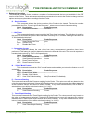
K Enhanced Operation
The Bluetooth enabled Probe contains a number of enhancements that are not available in the RF
version of the Probe. These enhancements allow commands to be sent to the Probe to change various
options and to query the state or readings from the Probe.
D - Device Number
This command allows the device number of the Probe to be viewed. The device number
presented to the Pc is “Pneu Logic Probe Dnnnnnn”, where nnnnnn is a six character string.
Cmd Description
Probe Response
D
View Device Number
Dnnnnnn
I - Idle Timer
This command allows the user to set the Idle Timer time in minutes. The idle timer is used by
the probe to shut down the probe if there has been no activity for “x” minutes. Setting the idle timer to
“0” will disable the idle timer.
Cmd Description
Probe Response
I
View Current Idle Time
Innn
Innn Set Idle Time
I0
Disable Idle Timer
L - Operation Counter
This command allows the user view how many measurement operations have been
performed. This feature is useful to determine the service interval of the unit. The count is output as a
hexadecimal number(E.g. “DA” is 218 operations).
Cmd Description
Probe Response
LT
View Tread Operations
Lnnnn
LP
View Pressure Operations
Lnnnn
LTC Reset Tread Counter
LPC Reset Pressure Counter
N - “Click” Mode Feature
This command controls the “Click” mode feature and enables you to turn the feature on or off
as desired.
Cmd Description
Probe Response
NTE Enable “Click” Mode
NTD Disable “Click” Mode
NT? View “Click” Mode setting
Ntn (E=enabled, D=disabled)
P - Pressure Reading
This command transmits the Pressure reading for the Probe. The value nnnn will vary based on the
units of measurement selected, if Actual A/D Readings then nnnn will represent the voltage detected
at the Pressure Sensor and will be a whole number. If any other measurement, PSI or BAR, is
selected then nnnn will be a decimal number (i.e. 0.166).
Cmd Description
Probe Response
P
View Pressure Reading
Pnnnn
T - Tread Depth Reading
This command transmits the Tread Depth reading for the Probe. The value nnnn will vary based on
the units of measurement selected, if Actual A/D Readings then nnnn will represent the voltage
detected at the Tread Depth Sensor and will be a whole number. If any other measurement, mm or
inches, is selected then nnnn will be a decimal number (i.e. 16.00).
Cmd Description
Probe Response
T
View Tread Depth Reading Tnnnn
© Trans-Logik Ltd. 2010
APPENDIX B-3
TYRE PROBE BLUETOOTH COMMAND SET
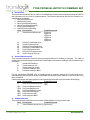
X - Recalibrate
This command allows the user to view or re-calibrate the Probe's internal references that are used in
the calculations for the units of measurements. The internal references that can be viewed or recalibrated are as follows:1 Idle Tread Depth level
2 Idle Pressure Level
3 0mm Tread Depth Reading
4 16mm Tread Depth Reading
5 0 PSI Pressure Reading
6 100 PSI Pressure Reading
Cmd Description
Probe Response
X
View internal References
X[1]nnnn
X[2]nnnn
X[3]nnnn
X[4]nnnn
X[5]nnnn
X[6]nnnn
X1
Set Idle Tread Depth level
X2
Set Idle Pressure level
X3
Set 0mm Tread Depth level
X4
Set 16mm Tread Depth level
X5
Set 0 PSI Pressure level
X6
Set 100 PSI Pressure level
XC
Clear values in X3 to X6
U - Units of Measurement
This command allows the Probe's units of measurements to be viewed or changed. The units of
measurement can be changed for both the Tread Depth and Pressure readings, the units allowed are
as follows:A
Actual A/D Readings
M
Tread reading in mm
I
Tread reading in inches
P
Pressure reading in PSI
B
Pressure reading in BAR
For the mm/inches PSI/BAR units of measurement to operate correctly the Probe must be recalibrated with two references for the Tread Depth (0 and 16mm) and Pressure ( 0 and 100 PSI) using
the X command.
If these references and report types are not set then the Probe will revert to Actual A/D Readings.
Cmd Description
Probe Response
U
View units of measurement UTn
Upn
UTA Set Tread Depth to Actual
UTM Set Tread Depth to mm
UTI
Set Tread Depth to inches
UPA Set Pressure to Actual
UPP Set Pressure to PSI
UPB Set Pressure to BAR
V - Software Version
This command transmits the Version number of the software running on the Probe.
Cmd Description
Probe Response
V
View Software VersionVxx.yy (dd-mm-yy)
© Trans-Logik Ltd. 2010
APPENDIX B-4
UPDATING THE TYRE PROBE FIRMWARE
The Tyre Probes contain software on an embedded microcontroller which enables the probe to
function. This software is called firmware. From time to time as the product is improved we release updated
versions of the firmware which may include new features, enhanced features or bug fixes. To see the benefits
of our improvements the firmware on your probe will require updating. Probe versions 103, 104 & 105
support “Bluetooth Updating”, where the firmware can be upgraded wirelessly using the Bluetooth
connection. All you require to do this is a standard Windows based desktop PC or Laptop which has
Bluetooth capability, our “Bluetooth Updater” software and a file containing the new firmware. Bluetooth
capability can be added to most current Windows PC's using an inexpensive Bluetooth USB adaptor. Using
this method it should take less than 10 minutes to update the Firmware.
Requirements:
K ·A Windows based desktop PC or Laptop.
K ·Bluetooth capability on the PC or Laptop (e.g. with a USB Bluetooth Adaptor).
K ·Bluetooth Updater Software (Ensure you have the latest version for 105 probes)
K ·New firmware file (e.g. P105_401.HEX).
K ·Probe for updating (Hardware Version PL1BT105 ONLY).
K ·Probe battery charger (e.g. Charger in Carry Case).
Important Notice:
! Always use the latest version of the Bluetooth Updater Software that is avaiable.
! The Probe will only successfully update if it is connected to the charger. Failure to
do this during update could cause the process to fail and may even damage the
firmware in the probe, which will make the probe unuseable.
! If for any reason the probe fails to program the updater software will show a red
cross to indicate an error. If the probe had started the program cycle before it failed
then the probe will remain in “Updating mode” until a successfull update has
occured. If this happenns then simply try the process again.
To update the firmware you need to;
K Install the Bluetooth Updater Software.
K Pair the probe to the Bluetooth enabled PC.
K Open and connect to the Bluetooth Virtual Serial Port.
K Run the Bluetooth Updater Application.
K Enter the correct COM Port number of the connection and click “Program”.
K When prompted select the new HEX file and click “Open”.
K The probe should now update. This should take between 2-10 minutes.
K When the probe is updated the Updater Application should show a green tick and the probe will
reset.
The Firmware Updater Software and update HEX files should be available to download off the Trans-Logik
website. Alternatively you can contact Trans-Logik for an update kit. More detailed information and
instructions can be also found on the Trans-Logik website.
© Trans-Logik Ltd. 2010
APPENDIX C-1