1
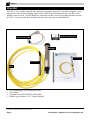
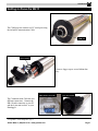
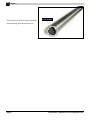
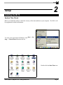
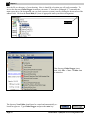
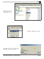
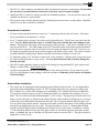
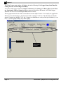
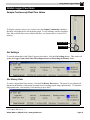
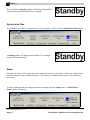
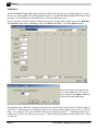
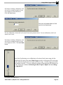
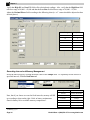
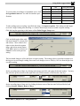
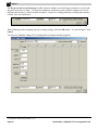
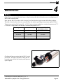
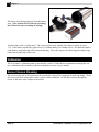
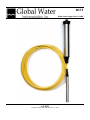
WL15 Water Level Logger User’s Guide 6/5/2002 Copyright © Global Water Instrumentation, Inc. 2002 Global Water ● (800)876-1172 ● www.globalw.com Page 1 Requirements • • • Windows 95, 98, ME, NT, 2000 or XP* 486DX 66MHz, 16MB RAM (Windows 95 base machine; later operating systems may require higher specifications) Available COM port Contact Information Global Water Instrumentation, Inc. 11257 Coloma Road Gold River, CA 95670 Toll Free: Local: Fax: E-mail: Web: 1(800)876-1172 1(916)638-3429 1(916)638-3270 [email protected] www.globalw.com Terminology In order to better understand this product manual, please be aware of the following terminology and formatting usage. Bolded terms (i.e. bold) indicate either a keyboard key, a word or icon that appears on your computer monitor screen or a phrase to be emphasized. Context will dictate which is indicated. Since it is assumed that users of this manual are familiar with mouse usage, many mouse operations are implied. The term “click” or “clicking” means to press and release the left mouse button. Similarly, “double-click” means to press and release the left mouse button twice in quick succession. For example, the phrase “Click the start button” should be interpreted as “Move the mouse pointer to the task bar and click the start button.” If any other mouse button is used in an operation, it will be specified in the documentation. The term “select” means to move the mouse pointer over the indicated target. For example the phrase “Select Toolbars from the View menu” means to move the mouse pointer over Toolbars after the View menu has been displayed. “Select” is normally used when the mouseover action will cause additional menus to display. The → symbol is used with submenu operations where the user should click the first and last items in the string separated by →. For example, the phrase “Click on File → New → Folder” means click on File, select New and click on Folder. When the documentation directs you to exit a program or window, you can generally do so by clicking the x graphic in the upper right-hand corner or by clicking File → Exit. x graphic *Windows® 95, 98, ME, NT, 2000 & XP are trademarks of the Microsoft Corporation Page 2 Global Water ● (800)876-1172 ● www.globalw.com Table of Contents CHAPTER 1: INTRODUCTION .............................................................................. 5 THE WL15 WATER LEVEL LOGGER .............................................................................................. 5 FEATURES .................................................................................................................................... 5 CHECKLIST ................................................................................................................................... 6 GETTING TO KNOW THE WL15 ..................................................................................................... 7 CHAPTER 2: SETUP .............................................................................................. 9 INSTALLING THE WL15 ................................................................................................................. 9 SYSTEM TIME CHECK ................................................................................................................... 9 GLOBAL LOGGER SOFTWARE INSTALLATION ............................................................................... 10 HARDWARE INSTALLATION .......................................................................................................... 14 General Installation Tips ........................................................................................................ 14 Groundwater Installation ........................................................................................................ 15 Surface Water Installation...................................................................................................... 15 Special Installations ............................................................................................................... 16 STORING THE WL15 ................................................................................................................... 16 CHAPTER 3: USING GLOBAL LOGGER SOFTWARE ...................................... 17 HARDWARE CONNECTION ........................................................................................................... 17 GLOBAL LOGGER STARTUP ........................................................................................................ 17 GLOBAL LOGGER FUNCTIONS ..................................................................................................... 19 Sample Continuously/Real-Time Values ............................................................................... 19 Get Settings ........................................................................................................................... 19 Get History Data .................................................................................................................... 19 Clear Memory ........................................................................................................................ 21 Synchronize Time .................................................................................................................. 22 Setup ..................................................................................................................................... 22 Datalogger Name and Sensor Warmup Time ..................................................................................................23 Calibration ........................................................................................................................................................24 Recording Interval and Memory Management .................................................................................................26 CHAPTER 4: MAINTENANCE ............................................................................. 29 BATTERY.................................................................................................................................... 29 CALIBRATION ............................................................................................................................. 30 SENSOR SCREEN SCREENING ..................................................................................................... 30 CHAPTER 5: TROUBLESHOOTING ................................................................... 31 COMM FAILURE .......................................................................................................................... 31 SENSOR READING INCORRECTLY ................................................................................................ 32 WATER IN THE VENT TUBE ......................................................................................................... 32 OTHER ISSUES ........................................................................................................................... 32 CHAPTER 6: WARRANTY ................................................................................... 34 APPENDIX A: WL15 DETAILED SPECIFICATIONS ........................................... 35 DATALOGGER ............................................................................................................................. 35 SENSING ELEMENT ..................................................................................................................... 36 HOUSING .................................................................................................................................... 36 CABLE ....................................................................................................................................... 36 APPENDIX B: WORKSHEETS ............................................................................. 37 CALIBRATING THE BAR GRAPH TO HIGHER OR LOWER RANGE .................................................... 37 Global Water ● (800)876-1172 ● www.globalw.com Page 3 CALIBRATING LEVEL SENSORS FOR DEPTH TO WATER READINGS ............................................... 38 APPENDIX C: CABLE CONFIGURATION ........................................................... 39 APPENDIX D: TERMINAL PROGRAMMING ....................................................... 40 COMMUNICATION COMMANDS FOR WINDOWS DATALOGGER ........................................................ 40 Page 4 Global Water ● (800)876-1172 ● www.globalw.com Introduction Introduction 1 The WL15 Water Level Logger Congratulations on your purchase of the Global Water WL15 Water Level Logger. This instrument has been quality tested and approved to provide accurate and reliable water level (water pressure) measurements. We are confident you will find the WL15 to be a valuable asset for your applications. Should you require assistance, our technical staff will be happy to help. The WL15 provides a datalogger with a submersible pressure transducer for remote monitoring and recording of water level, flow or pressure data. This highly reliable and accurate water logger records 24,400 readings and is programmable from one reading per second to one reading per day. Ranges of 0-3', 0-15', 030', 0-60', 0-120' and 0-250' are available. A 25' cable is standard, and optional cable lengths are available up to 1000'. The WL15’s datalogger is housed in a weather-resistant cylindrical enclosure that slips inside a 2-inch pipe. The logger is easily adapted with standard hardware for well head mounting or other installations. The WL15 includes Windows-based software, allowing easy upload of data to standard spreadsheet programs on a PC computer. The WL15's level sensor electronics are fully encapsulated with marine-grade epoxy, providing superior moisture protection over O-ring seals. During this process, the vent tube is sealed directly to the sensing element, preventing any moisture from damaging the sensor’s electronic components. The level sensor uses a unique silicon diaphragm to interface between the water and the sensing element. This silicon diaphragm is highly flexible and touches the sensing element, producing a sensor with exceptional linearity and very low hysteresis. The pressure transducer utilizes a stainless steel micro-screen cap to protect the sensing element. This protective cap has hundreds of openings, making fouling the sensor with silt, mud or sludge virtually impossible. Features Data • Windows based Global Logger* software • Tabular display/printout • Data in standard spreadsheet format • Communication cable included (RS232C) Logger • Weather resistant enclosure • Fits inside 2” pipe • Records 24,400 readings • 12 bit or 1/4,000 resolution • Battery powered Cable • Marine grade, heavy urethane jacket • Barometric pressure vent • Lengths up to 1000’ Sensor • Fully encapsulated submersible pressure transducer • Amplified and temperature compensated • High accuracy • 3/4” diameter wet-wet transducer (no vent moisture problems) *Copyright © Global Water Instrumentation, Inc. 2001 Global Water ● (800)876-1172 ● www.globalw.com Page 5 Chapter 1 Checklist Your WL15 was carefully inspected and certified by our Quality Assurance Team before shipping. If any damage has occurred during shipping, please notify Global Water Instrumentation, Inc. and file a claim with the carrier involved. Use the checklist to ensure that you have received everything needed to operate the WL15. Your sensor has been inscribed with the sensor range for easy identification. Global Logger Software* Communication Cable Datalogger User Manual Level Sensor Cable • • • • WL15 (Datalogger, Level Sensor and Cable) User Manual Communication Cable (RS232C COM Cable) Global Logger Software (3 1/2” Floppy Diskette) *Copyright © Global Water Instrumentation, Inc. 2001 Page 6 Global Water ● (800)876-1172 ● www.globalw.com Introduction Getting to Know the WL15 The COM port can connect to a PC serial port using the included Communication Cable. COM port lithium battery Unscrew logger cap to access lithium battery. DB-9 female connector 4-pin mini socket The Communication Cable has two different connectors. Connect the DB-9 female connector to your PC and the 4-pin mini socket* to your Datalogger. *See Appendix C: Cable Configuration, page 39 Global Water ● (800)876-1172 ● www.globalw.com Page 7 Chapter 1 The water level sensor is located inside the sensor housing, near the mesh screen. Page 8 sensor location Global Water ● (800)876-1172 ● www.globalw.com Setup Setup 2 Installing the WL15 System Time Check Before you install the software, check the accuracy of the time and date on your computer. The WL15 will be programmed with this information. To verify your system time in Windows, click Start → Settings → Control Panel from the task bar. Double-click the Date/Time icon. Global Water ● (800)876-1172 ● www.globalw.com Page 9 Chapter 2 Verify that your system is set to the correct time. If not, make the necessary changes and click the Apply button followed by the OK button. Exit the control panel. Global Logger Software Installation Insert the 3 1/2” floppy diskette labeled “Global Logger Software Version x.xx” (where x.xx is a version number such as 1.36) into your computer’s floppy disk drive. Normally, the floppy will be the computer’s “A” drive. Double-click the My Computer icon on your desktop. Double-click the floppy icon (normally listed as 3 ½ floppy (A:)). Page 10 Global Water ● (800)876-1172 ● www.globalw.com Setup Click on the file Global Logger.exe. Click Edit → Copy from the menu bar. Global Water ● (800)876-1172 ● www.globalw.com Page 11 Chapter 2 Save the file to a directory of your choosing. Note, it should be a location you will easily remember. To save to the directory Global Logger located on your main “C” hard drive (although “C” is normally the main system drive, the designation can vary from system to system), start by clicking the down carrot of the address field. Click on the Local Disk (C:) icon or appropriate main system drive designation. down carrot If the directory Global Logger is not listed, click File → New → Folder from the menu bar. The directory New Folder should now be created and automatically selected for typeover. Type Global Logger and press the enter key. Page 12 Global Water ● (800)876-1172 ● www.globalw.com Setup Double-click on the new Global Logger directory. Click Edit → Paste from the menu bar. A Copying… dialog box should now display. Wait for the copy process to complete. Global Water ● (800)876-1172 ● www.globalw.com Page 13 Chapter 2 To create a desktop shortcut, right-click the Global Logger.exe file you previously saved, select Send To and click on Desktop (create shortcut). You can now access your Global Logger* software directly from the desktop. Hardware Installation General Installation Tips • The WL15 has many applications and therefore many installation options. The WL15’s pressure sensor is fully submersible and may be suspended by its waterproof cables in the water to be monitored. • The data logger is not waterproof. It is water-resistant. This means that condensation, which can build up inside the enclosure during humid conditions, should not affect the performance of the WL15. However, if the data logger is submerged in water, it will corrode the electronics and cause it to stop working properly. Please ensure that the data logger will be clear from flooding and out of direct rainfall. • Do not install the WL15 in applications that contain solvents. Over time, many solvents can deteriorate the cable and the sensing element. • The accuracy of the sensor readings can be affected by such adverse conditions as overpressure, lightening strikes, improper care/handling, and physical damage or abuse. Page 14 Global Water ● (800)876-1172 ● www.globalw.com Setup • The WL15’s cable contains a vent tube that allows for barometric pressure compensation. Do not allow the vent tube to become kinked or obstructed as this may cause erroneous readings. • Install your WL15 so that it is easily accessible for calibration purposes. You may need to remove and reinstall it in the future, so plan ahead! • The pressure sensor will not function correctly if buried by mud, silt, leaves, or other debris. Install the sensor in a way that avoids these conditions. Groundwater Installation • For best results suspend the pressure sensor in a 2” monitoring well near the well screen. The sensor may be installed in well diameters 1” and up. • For a 2” diameter pipe (or larger), the sensor can be inserted directly. Slowly lower the sensor into the well. Warning: Do not allow the sensor to “freefall” down the well, this may cause damage to the sensor. The top of the data logger will rest on the top of the well pipe. A slip cap or a locking well cap can conceal the WL15. The cable length of the WL15 should be sized so the sensor will be positioned below the lowest expected water level, which is not necessarily the bottom of the well. The correct cable length is measured from the top of the data logger to the bottom of the sensor. The sensor’s measuring range should be slightly larger than the expected total amount of change in water level. • To shorten the cable in a 2” diameter or larger well, coil it around a 1” diameter stick or pipe and secure the cable at both ends with tie wraps or tape. Warning: Do not kink the cable; this may damage the internal vent tube. • The WL15 can be adapted to larger or smaller well casings by using standard PVC pipe reducers and fittings or Global Water’s Inside Well Option. • As factory programmed, the WL15 records depth of water above the sensor. If you want to use your WL15 to record depth to water readings, follow the worksheet Calibrating Level Sensors for Depth to Water Readings*. Surface Water Installation • The sensor may be submerged at the monitoring point and hung from its cable. It is recommended to protect the sensor and datalogger inside a 4” PVC drainpipe that will act as a protective stilling well. PVC schedule 40, or ABS sewer drainpipe is recommended. PVC schedule 40 electrical conduit has UV protectors and pre-formed “sweeps” or bends that enable it to conform to the contours of a riverbank. The level sensor will slide down through 45° or 90° sweeps. The pipe may be buried in the riverbank, secured with rocks, or fastened to the bank with large staples made by bending pieces of concrete reinforcing steel in half and driving them into the bank. Put a cap on the bottom end of the pipe to allow easy water flow past the sensors. Drop the sensor until it touches the bottom of the stilling well and then pull it up slightly and secure the cable. The pipe should have several ½” diameter holes drilled near the sensor location in order to eliminate any velocity effects on the sensor. In addition, a smaller ¼” hole should be drilled near the top of the pipe to allow air movement when the water goes up and down. A standard slip cap or a locking well cap can be used to secure the WL15. The pipe can also be adapted for a screw-on cap. *See Appendix B: Worksheets, page 38 Global Water ● (800)876-1172 ● www.globalw.com Page 15 Chapter 2 • In areas where vandalism is prevalent, 4” diameter galvanized steel pipe may be used for any exposed pipe. Plastic pipe, adapted to the steel pipe above water, may be used for the underwater section. A screw-on galvanized cap can then be used to cover the data logger. Two small pipe wrenches are required to access the WL15, but this installation is essentially bulletproof and vandal-proof. Special Installations • For flumes and weirs Global Water provides the Weir Stick Water Level Logger. This logger/sensor combination can be mounted inside a 2” diameter pipe that acts as its own stilling well, or the Weir Stick can be mounted in an existing stilling well. The weir stick is 3’ overall in length with a 2’ measuring range. • For measuring pressure in pipes, the level sensor may be purchased with a ¾” NPT thread on the sensing end. The sensor threads can be adapted to existing ball valves with standard pipefittings. • The WL15 Sewer Pipe Flow Option includes a level sensor built into a protective “mouse” housing and attached to a 12” stainless steel strap. When the sensor/straps are installed at the invert of a sewer or in a pipe, the data logger can be attached to a sewer’s stair rungs. If there is enough slack in the cable, the data logger can be accessed from the manhole above the stair rungs. • When installed in a pipe that is under 12” diameter, the steel straps spring into the pipe, holding the sensor in place. Additional fasteners are usually not required for this type of installation. • For a sewer pipe over 12” diameter, the sensor’s steel straps must be mounted into the pipe. The straps can be secured with molly or concrete bolts, or with marine-grade epoxy. Storing the WL15 The WL15 may be stored without any special provisions. Place the datalogger and sensor inside a bag to keep the instrument clean and store on a shelf or hang on a wall. Page 16 Global Water ● (800)876-1172 ● www.globalw.com Using Global Logger Software Using Global Logger Software 3 Hardware Connection Connect the DB-9 female connector of the included communication cable (RS232C) to the COM 1 serial port on your computer. If COM 1 is being used, either disconnect and/or disable the device on COM 1 or connect to COM 2*. 4-pin mini socket Connect the 4-pin mini socket of the communication cable (RS232C) to your WL15 COM port. Global Logger Startup Double-click the Global Logger icon on your desktop if you created a desktop shortcut during software setup. Otherwise, access the directory in which your the Global Logger.exe file is stored and double-click on the file. If you have not installed the Global Logger software or if you want to create a desktop icon, see Global Logger Software Installation**. * See Comm Failure, page 32. **See Global Logger Software Installation, pages 10 – 14 Global Water ● (800)876-1172 ● www.globalw.com Page 17 Chapter 3 The Global Logger main window will display data in the following fields: Logger Name, Date/Time, Recording Interval and Recordings in Memory. Access the Global Logger functions Sample Continuously, Get Settings, Get History Data, Clear Memory, Synchronize Time and Setup through the main menu check box and buttons. All Global Logger functions can also be accessed through Action on the menu bar. The bar graph on the left side of the screen indicates current depth of sensor. For example, the graph in the following screen shot displays a 120 foot sensor with a reading of 79.83 feet. This data indicates that the sensor is currently at a depth of 79.83 feet. Sensors are calibrated to a variety of unit specifications (i.e. meters), so your bar graph readings may differ slightly. depth bar graph Global Logger functions Page 18 Global Water ● (800)876-1172 ● www.globalw.com Using Global Logger Software Global Logger Functions Sample Continuously/Real-Time Values To display real-time values every second, select the Sample Continuously checkbox. Readings will display below the depth bar graph. To stop readings, unselect checkbox. Note, that real-time data is not recorded; therefore, you cannot retrieve it from WL15 memory. current reading past readings Get Settings To refresh information in the Global Logger main window, click the Get Settings button. This action will update the Logger Name, Date/Time, Recording Interval and Recordings in Memory fields. Get History Data To retrieve logged data from memory, click the Get History Data button. The speed of your upload will depend on the number of data points recorded (more recordings equals longer upload time). To minimize long upload times, clear memory* after backing it up to disk**. * See Clear Memory, pages 21 – 22 **See Get History Data, pages 20 – 21 Global Water ● (800)876-1172 ● www.globalw.com Page 19 Chapter 3 A Historical Data Viewer window will display. This window lists each data point by date/time and reading value. If there are more data points in memory than will fit in the data view window, use the scroll bar to scroll through the list of readings. readings listed by Date/Time and reading value (in this case Feet) use scroll bar to scroll through list If you want to save current readings, click the Save to File button. A Save As window will display. If you want to save your file to a directory other than the one displayed, click the down carrot of the Save in: field and click on the device (i.e. hard disk drive, floppy disk drive, etc.) you want to save the file to. Page 20 down carrot Global Water ● (800)876-1172 ● www.globalw.com Using Global Logger Software Double-click the directory or subdirectory you want to save to. If you want to change the file name click anywhere in the File name: field and type the desired name. However, do not change the .csv extension. This extension ensures the file will be recognized as a comma separated value (*.CSV) file. You can open CSV files in spreadsheet programs such as Microsoft Excel*. Click Save to save the file. change name in file name field To remove zero readings, click the Pack button. Note, this operation will not remove the initial zero reading. Since the pack function does not change the readings stored in memory, you will need to Save to File to preserve the pack operation. If you exit and then reenter the Historical Data Viewer window, all readings (including zero readings) stored in memory will display regardless of any prior pack operation. Click OK to exit the Historical Data View window. Clear Memory To clear your WL15’s memory of readings click the Clear Memory button. A confirmation dialog box will display. Click Yes to clear history or No to keep readings. *Windows® Excel is a trademark of the Microsoft Corporation Global Water ● (800)876-1172 ● www.globalw.com Page 21 Chapter 3 If you click Yes, a Standby graphic will display in the middle of your monitor screen while the memory is purged. Synchronize Time To synchronize your WL15’s internal clock to your computer’s clock*, click the Synchronize Time button. A Standby graphic will display in the middle of your monitor screen while synchronizing. Setup Note that your Water Level Logger has come completely setup from our factory. It has been calibrated and tested for optimal accuracy and performance. If you choose to recalibrate your sensor, use the following procedures. To begin calibration and/or to change time interval settings, click the Setup button. A Global Water Setup window will display. *See System Time Check, pages 9 – 10 Page 22 Global Water ● (800)876-1172 ● www.globalw.com Using Global Logger Software Datalogger Name and Sensor Warmup Time If you want to change the datalogger name, click in the Name field and type in a new name. Global Water recommends that the Sensor Warmup Time field be set at 3 seconds to supply the level sensor with adequate power for accurate data measurements. This setting dictates the length of time power is applied to the level sensor before the datalogger takes a reading. For example, if you set your WL15 to record a reading every 20 minutes at fixed intervals and the process begins at 12:00:00, power will be applied to the level sensor immediately and a reading taken at 12:00:03. At 12:20:00, power will again be applied to the level sensor, and the datalogger will take a reading at 12:20:03. Note that if the recording interval fields are less than or equal to the Sensor Warmup Time field, the sensor is powered continuously. To change warmup time, click in the Sensor Warmup Time field and enter the desired time (0 –15 seconds). You may also click the up/down arrows to the right of the text field to increase or decrease the value by 1. recording interval fields Global Water ● (800)876-1172 ● www.globalw.com Page 23 Chapter 3 Calibration Change the Sensor Type or EU (engineering units) field to the unit type you are calibrating to (i.e. meters, feet, etc.) by clicking in the field and typing the unit name. Note that the Sensor Type or EU field is only a text label. Actual readings are determined by the following calibration steps. In case you make a mistake during the calibration process, write down the existing values in the High Raw and Low Raw fields before continuing (in this case 64435 and 12704). Click the Calibrate button. Enter the maximum unit range of the level sensor (120 for a 120’ sensor in this example) in the highest value text field and click the Next button. If performing a dry calibration, insert the sensor into your water pressure meter and set to full scale range of your WL15. If performing a wet calibration, insert level sensor to a water depth of at least 10% of full scale range. For example a 120’ sensor should be calibrated at a depth of at least 12’. Calibrating at greater percentages (up to 100%) provides greater accuracy. Calibration depth should be measured from water surface to sensor tip. Page 24 Global Water ● (800)876-1172 ● www.globalw.com Using Global Logger Software For both wet and dry calibrations, wait at least five seconds for the level sensor to adjust to current PSI level. Click the Next button. Enter 0 in the lowest value text field and click the Next button. For dry calibrations, release the level sensor from water pressure meter. For wet calibrations, take level sensor out of water. For both wet and dry calibrations, wait at least five seconds for the level sensor to adjust to 0 PSI. Click the Finish button. Note, that if performing a wet calibration at a fraction of total sensor range, the bar graph on the left side of the main Global Logger window will interpret full scale range at the calibration depth instead of actual total sensor range. All other logger operations will perform correctly. To revise calibration settings so that the graph will function correctly, follow the worksheet Calibrating the Bar Graph to Higher or Lower Range in Appendix B*. *See Appendix B: Worksheets, pages 37 Global Water ● (800)876-1172 ● www.globalw.com Page 25 Chapter 3 Verify that High EU and Low EU fields reflect desired unit readings. Also, verify that the High Raw field reflects a range of 60,000 – 65,000 and that the Low Raw field reflects a range of 10,000 – 15,000. Adjust the Decimal Places field according to the following chart (i.e. a 3’ sensor should be adjusted to three decimal places). wl sensor range decimal places 3’ 3 15’ 2 30’ 2 60’ 1 120’ 1 250’ 1 Recording Interval and Memory Management Select the interval type by clicking the down carrot of the Sample field. To repeatedly record values at a specified interval, click for fixed interval. down carrot Note, that if you choose to record at fixed intervals, memory will fill up according to chart on the right. Refer to battery maintenance chart for battery life to available memory comparisons*. Recording Interval Time 1 second 6 hours, 49 minutes 1 minute 17 days 5 minutes 84 days 15 minutes 254 days 30 minutes 509 days 1 hour 1018 days *See Battery, page 29 Page 26 Global Water ● (800)876-1172 ● www.globalw.com Using Global Logger Software To record values according to a logarithmic curve, click for logarithmic interval. See chart for timeline specifications. Time Frame Readings per time unit Expected total readings during Time Frame 0-19 seconds As fast as possible 1000 20-59 seconds 1 per 1 second 40 60-599 seconds 1 per 12 seconds 45 10-99 minutes 1 per 2 minutes 45 100-999 minutes 1 per 200 minutes 45 1000-9999 minutes 1 per 1440 minutes 45 To take readings upon exceeding a specified unit range, click upon exception. This setting sets the logger to record a single reading after detecting a ± variance from the previously recorded exception reading. Click the long bar appearing at the bottom of the Global Logger Setup menu Click and hold toggle slider with left mouse button (i.e. do not click and release). Move slider left or right to select desired exception range, and release mouse button. Click OK to preserve selection or Cancel to revert to the previous setting. toggle slider The bar should change to reflect the latest exception setting. The setting in these screenshot examples sets the logger to record a single reading after water level changes (rises or falls) by 10.2 feet from the previous exception reading. Set the recording interval digit, by clicking in the every text field, and typing the desired number. You may also click the up/down arrows to the right of the text field to increase or decrease the value by 1. up/down arrows Set the recording interval time unit, by clicking the down carrot of the time unit field (not labeled) and clicking Seconds, Minutes, Hours or Days. Global Water ● (800)876-1172 ● www.globalw.com Page 27 Chapter 3 The Wrap records at end of storage checkbox dictates whether or not the logger continues to record readings after its memory is filled. To overwrite readings in synchronous order (earliest readings are overwritten first) after memory is filled, click the checkbox. To preserve readings and stop recording after memory is filled, leave box unchecked. After calibrating and/or changing interval recording settings, click the OK button. To cancel changes, click Cancel. You may also manually change WL15 settings directly using a terminal program*. *See Appendix D: Terminal Programming, page 40 Page 28 Global Water ● (800)876-1172 ● www.globalw.com Maintenance 4 Maintenance Battery Global Water recommends that the battery voltage be physically checked based on your recording interval*. Refer to the following table. Note, that the WL15 uses 60µA while “sleeping” and 3mA plus the signal current while taking readings. This table is based on the worst-case scenario where the sensor is providing the maximum signal of 20mA. Temperature can also affect battery life. A WL15 in an environment that has a sustained temperature of 23° C will run 5% longer than a unit that has a sustained temperature of 0° C. Recording Interval Theoretical Battery Life 1 second 43 hours Recommended Time Between Battery Check 36 hours 1 minute 34 days 1 month 30 minutes 424 days 6 months 1 hour 526 days 6 months 1 day 685 days 6 months Checking the battery requires that the WL15 cap be unscrewed. The battery should be visible and can be gently removed from the housing with fingers or a pair of pliers. *See Recording Interval and Memory Management, pages 26 – 28 Global Water ● (800)876-1172 ● www.globalw.com Page 29 Chapter 4 The battery must be disconnected from the battery strap. Note, that the WL15 will stop recording, but will not lose any recordings or settings. Test the battery with a voltage meter. The sensor will not work reliably if the battery voltage is below 7.5V. If the battery needs to be replaced use a 9V lithium battery for reliable service. Re-attach the battery to the battery strap and gently slide it into the housing. Screw the cap on to the data logger housing, being careful not to pinch any of the wires. Calibration The level sensor’s calibration must be periodically verified. Global Water recommends checking the sensor’s calibration with a sounder or other measuring device once every 6 months. Sensor Screen Cleaning The screen on the end of the sensor must be periodically checked for clogging from mud and sludge. Wash the screen with clean water and/or scrub it gently with a toothbrush. Do not insert objects through the screen, as this may cause damage to the sensor. Page 30 Global Water ● (800)876-1172 ● www.globalw.com Troubleshooting Troubleshooting 5 Comm Failure If Global Logger software displays Comm Failure in the Logger Name field, perform the following steps • • • Verify that the communication cable is securely connected to the data logger and to your computer*. Check the battery voltage on the logger**. Make sure that your computer is correctly set up to use your communication channel 1 (COM 1). Refer to the settings below for comparison. * See Hardware Connection, page 17 **See Battery, page 29 Global Water ● (800)876-1172 ● www.globalw.com Page 31 Chapter 5 • If you only have access to COM 2, then an *.ini file must be created. Open Notepad and type the text exactly as it appears in the following screenshot. Change the directory to the Windows folder of your main drive if you are using Windows 95, 98, ME or XP or to the WINNT folder of your main drive if you are using Windows NT or 2000. Save the file as global logger.ini. • Make sure that no other software or device is using COM 1, such as an infrared port or palm synching software. Sensor Reading Incorrectly • • • Verify that the vent tube has not been kinked or sealed. The sensor uses this tube to compensate for barometric pressure changes. Clean the sensor following the maintenance instructions*. Recalibrate the sensor using the calibration methods described in the Calibration section of this manual**. Water in the Vent Tube If water gets into the cable’s vent tube, place it next to a heater for 24 hours to dry the inside of the cable. Other Issues • • • Refer to the manual for proper set-up. Check all connections. Call Global Water for tech support: 800-876-1172 or 916-638-3429 (many problems can be solved over the phone). Fax: 916-638-3270 or Email: [email protected]. When calling for tech support, please have the following information ready; 1. Model number 2. Unit serial number 3. P.O. number the equipment was purchased on. 4. Our sales number or the invoice number. 5. Repair instructions and/or specific problems relating to the product. Be prepared to describe the problem you are experiencing including specific details of the application, installation, and any additional pertinent information. * See Sensor Screen Cleaning, page 30 **See Calibration, pages 24 – 26 Page 32 Global Water ● (800)876-1172 ● www.globalw.com Troubleshooting • In the event that the equipment needs to be returned to the factory for any reason, please call to obtain an RMA number (Return Material Authorization). Do not return items without an RMA number displayed on the outside of the package. Clean and decontaminate the WL15 if necessary. Include a written statement describing the problems. Send the package with shipping prepaid to our factory address. Insure your shipment, since Global Water’s warranty does not cover damage incurred during transit. Global Water ● (800)876-1172 ● www.globalw.com Page 33 Chapter 6 Warranty 6 Global Water Instrumentation, Inc. warrants that its products are free from defects in material and workmanship under normal use and service for a period of one year from date of shipment from the factory. Global Water’s obligations under this warranty are limited to, at Global Water’s option: (I) replacing or (II) repairing; any products determined to be defective. In no case shall Global Water’s liability exceed the products original purchase price. This warranty does not apply to any equipment that has been repaired or altered, except by Global Water Instrumentation, Inc., or which has been subject to misuse, negligence or accident. It is expressly agreed that this warranty will be in lieu of all warranties of fitness and in lieu of the warranty of merchantability. The warranty begins on the date of the invoice. Page 34 Global Water ● (800)876-1172 ● www.globalw.com WL15 Detailed Specifications Appendix A: WL15 Detailed Specifications A Datalogger Inputs • Channels: • Range: • Storage Resolution: • A/D Resolution: Data Storage • Memory Size: • Type: • Intervals: • • Time Accuracy: Time Format: 1 Analog 4 – 20 mA 1 / 65535 (16 bit) 1 / 4095 (12 bit) 2MB (24,000 recordings) non-volatile Flash 1 – 256 seconds, 1 – 256 minutes, 1 – 256 hours, or 1 – 256 days 0.0015% Month / Day / Year Hour / Minute / Second Communication • Speed: • Data Transfer: • Type: 38,400 kbs 2MB / 4 min. RS232C (Serial) Electrical • Battery: • Back-up Battery: • Sleep Current: • Wake Current: • Communication Current: 9V Lithium (1A / h) 3V Lithium (950 mA / h) 60µA 3 mA + Sensor (4 – 20 mA) 100 mA Environmental • Operating Temperature: • Storage Temperature: • Humidity: -40 to 75° C (-40 to 170° F) -50 to 90° C (-60 to 200° F) 0 to 95% Non-Condensing (Conformal Protection Coating) Physical Dimensions • Body OD: • Cap OD: • Length: • Weight: 45mm (1.77”) 57mm (2.24”) 315mm (12.4”) ~450g (16 oz.) Global Water ● (800)876-1172 ● www.globalw.com Page 35 Appendix A Sensing Element • • • • • • • • • • • • • • • • Output: Range: Accuracy: Linearity and Hysteresis: Resolution: Operating Voltage: Current Draw: Warm-up Time: Operating Temperature: Size of Probe: Weight: Overpressure: Burst Pressure: Material: Type: Compensated Temperature Range: 4 – 20 mA 0 – 3’, 0 – 15’, 0 – 30’, 0 – 60’, 0 – 150’, 0 – 250’ ±0.2% FS (35° F to 70° F) ±0.1% FS Infinitesimal (Analog) 10 – 36 VDC 4 – 20 mA 10 ms minimum -40 to +85°C (-40 to +185°F) 3/4" diameter x 4 1/2" long 0.5 lb X4 X10 Fluorosilicone Differential (Wet/Wet) 0 to 50°C (32 to 122°F) submerged Housing • • • • Material: Diameter: Length: Weight: 304L SS 19 mm (0.75”) 200 mm (8”) ~115g (4 oz) Cable • • • • • • • • Conductors: Jacket Material: Optional Jacket: Cable OD: Vent Tube: Shield: Temperature range: Weight: Page 36 4 each 22 AWG 87A shore hardness Polyurethane Fluorinated Ethylene Propylene (FEP) Teflon 7.8 mm (0.307”) HD Polyethylene Aluminum Mylar -30 – 85°C (-22 – 185°F) ~65 g / m (0.7 oz / ft) Global Water ● (800)876-1172 ● www.globalw.com Worksheets Appendix B: Worksheets B Calibrating the Bar Graph to Higher or Lower Range With some sensors it is either impractical or unfeasible to reach the full-scale or lower scale of its range. This will not affect the actual reading of the datalogger but it will cause the bar graph to work incorrectly. Here are the equations for finding new limits on the bar graph. First take the two coordinates that were found during calibration*. (High EU __________, High Raw __________) and (Low EU __________, Low Raw __________). Now calculate the slope using this equation: m = (High Raw – Low Raw) / (High EU – Low EU) m = ___________ Next find the y-intercept: b = High Raw - (m x High EU) b = ___________ Now you can calculate the new “Raw” value for any Engineering Unit. New Raw = (m x New EU) + b New Raw = ___________ Finally, enter these new “Raw” values into your datalogger and verify the readings are correct*. *See Calibration, pages 24 – 26 Global Water ● (800)876-1172 ● www.globalw.com Page 37 Appendix B Calibrating Level Sensors for Depth to Water Readings Note, that to take depth to water readings, the bar graph must be calibrated to the full scale of the sensor. Follow the worksheet Calibrating the Bar Graph to Higher or Lower Range*. The first step is to find the Total Depth of the sensor. This is the distance from the end of your sensor to your datum. (Cable lengths from the factory are not exact. You may need to measure for precise distances.) Total Depth = _____________ Next, find the maximum Sensor Depth (range of the sensor). In the Calibration** section of the software, you can find this value by using the following equation: Sensor Depth = | High EU______ - Low EU______ | Sensor Depth = ___________ Now you can find your new Engineering Units using these steps: New Low EU = Total Depth New Low EU = ___________ New High EU = Total Depth – Sensor Depth New High EU = __________ Finally, enter these New EU values into your datalogger and verify the readings are correct**. * See Appendix B: Worksheets, page 37 **See Calibration, pages 24 – 26 Page 38 Global Water ● (800)876-1172 ● www.globalw.com Cable Configuration C Appendix C: Cable Configuration The following diagram details the pin layout of the male communications cap on the WL14/15 Datalogger series. The chart explains the communications wiring. Comm. Cap Pin Number 1 Comm. Cap Wire Color Green 2 Blue DTR 4 3 Violet Rx 3 4 Red Tx 2 Global Water ● (800)876-1172 ● www.globalw.com Function 9 pin D-sub Pin Number (Male) Dig. Ground 5 Page 39 Appendix D Appendix D: Terminal Programming D Communication Commands for Windows Datalogger The following is a chart of commands that can be sent to the Windows Datalogger through a terminal program. Command Description Page 40 D Set Date T Set Time ? Get number of data points h Get first historical data point a Get historical data point again X Abort i Get next historical data point (increment) E Erase r Get real time data point ! Set description 1 Get description @ Set Units 2 Get Units # Set Raw Scale 3 Get Raw Scale $ Set Engineering Unit Scale (EU) 4 Get Engineering Unit Scale (EU) N Set Name n Get Name S Set Sample interval s Get Sample interval Global Water ● (800)876-1172 ● www.globalw.com