1
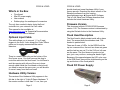
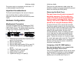
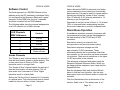
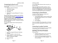
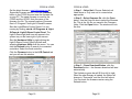
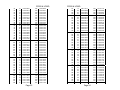
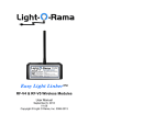
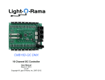
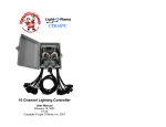
CF50D Cosmic Color Flood shown (UF50D is identical except for LED chip) CF50D & UF50D DMX 50W RGB and Black Light LED Floods User Manual November 20, 2014 V1.01 Copyright © Light O Rama, Inc. 2014 CF50D & UF50D Table of Contents Introduction .............................................................. 4 What’s in the Box..................................................... 5 Optional Input Cable ................................................ 5 Hardware Utility Version .......................................... 5 Firmware Version .................................................... 6 Flood Head Description ........................................... 6 Flood DC Power Supply .......................................... 6 Important Considerations ........................................ 7 Hardware Configuration ........................................... 7 Weatherproof Connectors .................................... 7 Removing the Back Cover ................................... 8 Assigning a Unit ID / DMX address ...................... 8 Using the Hardware Utility ................................ 9 Software Control .................................................... 11 LOR Channels DMX Addresses......................... 11 Strobe Channels ................................................ 11 Stand Alone Operation .......................................... 12 Hardware Description ............................................ 14 Input Header ...................................................... 14 LOR/DMX Network Jumpers .............................. 15 Network Jacks.................................................... 15 Reset/Self-test DIP Switch 12 ........................... 15 Status LED ......................................................... 16 Unit ID or DMX Start Address ............................ 16 UV/RGB Selection DIP Switch ........................... 16 Connecting the Flood to a PC ............................ 17 Connecting to a Show Director .......................... 18 Connecting to another Controller ....................... 18 Updating the Flood Firmware ................................ 18 Appendix A ............................................................ 21 DIP Switch Address Settings ................................. 21 Specifications ........................................................ 27 Introduction The Light-O-Rama (LOR) RGB CF50D Cosmic Color Flood and the UV UF50D Black Light Flood are LED lighting systems that have the controller built into the flood head with a separate DC power supply. The controller understands and automatically detects both LOR and DMX protocols. It has two weatherproof RJ45 dangles that can be jumpered for LOR or DMX (E1.27-2) network wiring. The RGB is capable of producing sixteen million colors. The Black Light (UV) flood head produces approximately a 390 nm color. The entire system is weatherproof and UV resistant. Both floods have five channels, R, G & B for the color flood and brightness, n/a, n/a for the UV flood. These channels are followed by two strobe effect channels. The strobe effect channels give precise control over strobing with the RGB/UV channels permitting any color/brightness to be strobed. The Windows Showtime software is used to design and build Sequences (controller commands that may be choreographed to audio/music.) These user created sequences and/or pre-programmed musical sequences available from LOR and other companies are then arranged into Shows. These shows are played by your PC or one of the LOR Show Directors. Page 4 CF50D & UF50D What’s in the Box Flood head 60w DC power supply User manual Rubber plugs for weatherproof connectors The only item needed to daisy chain the flood controller into your network is a Cat5 cable. This manual is also available at www.lightorama.com ► Support ►Documentation ► CF50D/UF50D User’s Manual. CF50D & UF50D should download a new Hardware Utility if your license permits. Download the latest version of the Showtime software from this location: www.lightorama.com ►Support ►S3 Software. This is a full ShowTime Software download that includes the latest Hardware Utility. Firmware Version This document reflects CF50D/UF50D firmware version 1.00. The firmware version is determined by using the Refresh button in the Hardware Utility. Flood Head Description Optional Input Cable This cable allows you to connect 1, 2 or 3 input triggers to the flood. It also brings the 10vdc 300ma power out to supply accessories like motion detectors. There is a small rubber plug on the bottom of the flood’s rear cover. You must remove this plug to route this cable into the flood head. You will have to seal the opening with silicone. Be sure to leave enough cable inside the flood head so that should you need to remove the rear cover, you will be able to move it away from the flood head. The flood head is black painted metal with a glass front. The screws/bolts are stainless steel. The bracket is painted steel. There are 6 rows of LEDs, for the RGB flood, the top two rows are blue, the next two down are green and the last two are red. For the UV flood, all rows are the same. The flood does not produce a hot spot, just a very uniform, rectangular band of light. Because of the space between the LED color rows in the RGB flood, there will be slight banding on the top and bottom of the flood pattern. Flood DC Power Supply Hardware Utility Version The version of the Hardware Utility appears in the title bar to the right of “Light-O-Rama Hardware.” If the version number is less than 3.1.xxx, then you Page 5 Page 6 CF50D & UF50D The power supply is a separate unit with about 1.5’ of cable between it and the flood. Important Considerations The flood heads dissipate a fair amount of heat so care should be taken to make sure there is adequate air flow around the flood head and power supply. Hardware Configuration Weatherproof Connectors The flood is equipped with two weatherproof RJ45 connectors to allow it to be daisy chained into your LOR or DMX network. The picture below show how to attach your network cables to the flood. 1. Take care not to loosen any of part [4] which goes to the flood head. 2. Remove end cap [1] first. 3. Remove part [3] next. 4. Remove split rubber washer [2] from part [3] 5. Feed the Cat5 cable through the parts as shown. 6. Plug your Cat5 cable into part [4]. 7. Tighten part 3 on to part [4]. 8. Push part [2] into part [3]. 9. Tighten end cap [1] on to part [3]. Page 7 CF50D & UF50D There are two cable diameter rubber plugs that should be installed in unused connectors to prevent water from reaching the RJ45 jack(s). Removing the Back Cover The back cover should only be removed if absolutely necessary. Re-assembly may result in the flood not being weatherproof and may result in damage to the internal cabling. The Unit ID or DMX Start Address should be set using the Hardware Utility. To remove the rear cover, remove the 4 screws. The silicone gasket is glued to the flood head and should stay with it when the back cover is removed. You may want to disconnect the RJ45 network cables to gain easier access, but this is not normally necessary. When re-installing the back cover, make sure no cables are pinched by the cover and that the cover sits flat on the silicone gasket. Tighten the screws in an X pattern (upper left, lower right, upper right, lower left.) The screws must be snug, but be careful not to over tighten because you may strip the screws or distort the case/cover causing leaks. Assigning a Unit ID / DMX address See warning about back cover removal in the Removing the Back Cover section. The Unit ID and DMX address can be set two ways; via the internal DIP switches or via the Hardware Utility. The flood is shipped with the Unit ID DIP switches set to 0 and the Unit ID set to 01. Page 8 CF50D & UF50D CF50D & UF50D When the Unit ID/DMX address DIP switches are set to zero, these parameters are set by the Hardware Utility and retained in the microprocessor’s permanent memory. In this case, the DMX address is set to ((Unit ID – 1) * 5) + 1. Using the DIP switches will allow you to override the memory Unit ID. In this case you can set any DMX start address. See Appendix A for switch settings. Note that switch 1 is the most significant bit and switch 9 is the least significant bit. Switch 1 is only used for the DMX address. Using the Hardware Utility If you have not installed the Light O Rama Windows Showtime Software, do it now. You will also need one of the RS485 adapters installed. See the Connecting the Flood to a PC section for more information. Plug the flood power supply into AC power. If you have the rear cover removed, the Status LED will blink about twice/second. This means that the controller has booted and is waiting for the PC to talk to it. See the Weatherproof Connectors section for information on connecting the CAT5 cable from the RS485 adapter to the flood. Start the Hardware Utility – click start ► All Programs ► Light-O-Rama ► Light-O-Rama Control Panel. There will be a light bulb with a red halo on the right side of the task bar at the bottom of the screen. Right-click the light bulb and select Hardware Utility from the menu. Make sure the LOR Control tab is selected. You will see this window:. Page 9 Click the Auto Configure button in the Setup Comm Port section. The Hardware Utility will search for the COM port that your RS485 adapter is plugged into and select it. When assigning a unit ID, only one controller may be plugged into the RS485 adapter on the PC. Be sure you do not have more than one controller connected. Steps to set/change unit ID: 1. In the Change Existing ID section, use the Old Unit ID drop-down menu to select Any Unit, then click OK in the warning box for changing all unit IDs, there should only be one unit attached. 2. Use the New Unit ID drop down menu to select “01” or whatever Unit ID you want. 3. Click the Change Unit ID button to set your flood’s unit ID. You will see a Unit ID Changed box – click OK. Page 10 CF50D & UF50D Software Control The flood appears in a LOR/DMX Network at the address set by the DIP switches or Hardware Utility. It is configured in the Sequence Editor as 5 regular channels; for the RGB flood, the first 3 channels should be combined into an RGB channel. The following tables show the channel assignments on a LOR network or in a DMX universe. LOR Channels DMX Addresses feature allows the RGB/UV channel(s) and strobe on time channel to be set without an uncontrolled flash occurring. This can be useful to create realistic lightning by varying the “strobe off time” channel from 1% intensity to 2% intensity and back to 1% intensity to get a single flash. Remember to set the “strobe off time” to 1% at least 1/20th of a second before manipulating the other flood control channels to avoid an unwanted flash. Stand Alone Operation Controls 1 R or UV 2 G or na 3 B or na 4 Strobe on time 5 Strobe off time Strobe Channels The “Strobe on time” channel selects the amount of time the flood head is turned on while strobing. This on time varies from 8.33ms to 83.3ms. Higher intensities result in a longer flash. The “Strobe off time” channel selects the amount of time the flood head is off while strobing. This off time varies from 2 seconds to 8.33ms. Higher intensities result in a faster flash. Setting the “Strobe off time” channel to 1% intensity is a special case. This puts the flood head in strobe mode but does not allow it to flash. Using this Page 11 CF50D & UF50D A standalone animation sequence (sequence with no accompanying audio) can be downloaded into the flash memory of the CF50D and UF50D controllers. Stand-alone memory is external to the microprocessor and survives power cycling. Stand-alone sequence storage can hold approximately 10,000 commands. These commands can also be for controllers other than this controller, so this controller can direct a network of controllers. There are no restrictions on the types of LOR controllers in this network. The sequence is designed and tested using the Showtime Software Sequence Editor. When you are happy with the sequence, save it and stop the Sequence Editor. Start the Hardware Utility and click the Refresh button to find the flood controller. Use the drop down menu next to the Refresh button to select the controller. Click the Standalone button at the bottom of the window. Select one of “Run when power is on,” Page 12 CF50D & UF50D “Input (norm open switch)” or “Input (norm closed switch.)” Click the Send Trigger info to Unit button. Only trigger input 1 can be used for this purpose. Finally, Use the Open button to browse to your sequence and click the Download button. You also use this screen to remove downloaded standalone sequences. Note that all downloaded sequences are removed. You can also remove standalone sequences by turning the controller off, turning on DIP switch 12 and then powering it up. Because you must remove the cover to do this, it is recommended that you use the Hardware Utility. You must power the controller off to completely wipe out the sequence. CF50D & UF50D Hardware Description The following picture shows the inside of the flood head. INPUT HEADER STATUS LED DIP CONFIGURATION SWITCHES LOR/DMX NETWORK SELECTION JUMPERS R45 JACKS Input Header The input header provides three inputs that can be sensed by the PC or used to trigger a standalone sequence. 10vdc at 300ma is also available for accessories like motion sensors. Here’s how to wire a switch to input 1: Page 13 Page 14 CF50D & UF50D All inputs must be simple switches that connect Input1/2/3 to GND. Input 1 is used to trigger a standalone sequence or as an interactive input for shows. Inputs 2 and 3 are used as interactive inputs for shows. Input 2 is inverted, meaning that it is on when the switch is open. Use input 2 for devices like motion sensors that open the circuit when activated. CF50D & UF50D Status LED Blinks twice per second if the flood has booted correctly Solid on if the flood sees a network director – PC, Show Director or DMX source Blinks one long on and a short off repeatedly if in the bootloader. This means that the firmware is not loaded or corrupted. See the Updating the Flood Firmware section to load firmware Flashing rapidly indicates resetting because DIP switch 12 is on. LOR/DMX Network Jumpers These 4 jumpers select how the RJ45 jacks are wired, either standard LOR network wiring or E1.272 DMX wiring. These jumpers have no effect on the floods ability to automatically detect the attached LOR or DMX network; they only affect the pin-out of the jacks. Network Jacks Two RJ45 jacks used to daisy chain this controller into a LOR or DMX network. These are normally extended outside the flood head through the included weatherproof RJ45 connectors. Reset/Self-test DIP Switch 12 Power the flood off, set DIP switch 12 to on and power the flood up. This will reset the flood and remove any standalone sequence. After resetting, the flood will run a simple test program to show that it is functioning properly. In a darkened environment, the status LED can be seen without removing the back cover by prying out the input cable rubber plug on the bottom of the back cover. Remember to replace it. Unit ID or DMX Start Address Positions 1 through 9 on the DIP switch are used to set the Unit ID and/or DMX address. The flood is normally shipped with all set to off which means the Unit ID and DMX address are set via the Hardware Utility. If any of these switches are on, the Unit ID and/or DMX start address is specified by these switches. Position 9 is the least significant bit. See Appendix A for values. UV/RGB Selection DIP Switch DIP switch 11 must be ON for the UF50D and OFF for the CF50D. Page 15 Page 16 CF50D & UF50D Connecting the Flood to a PC You will need the following to connect your Flood light to a PC: Showtime Windows Software USB RS485 Adapter CAT5 LAN cable Your flood Windows PC running Windows XP, Vista or Win7 or 8 The first three items are available in the LOR SPKST Generic Starter Package. www.lightorama.com ► On-line Store ► Components. You will have to choose an RS485 adapter type. Choose the USB485 if you have no intention of going wireless from your PC to the controller. If wireless is desired, get the USB485B. The following diagram shows how the pieces fit together: CF50D & UF50D If your USB adapter has more than one jack, you can use either. Open the weatherproof RJ45 connector. Use a Cat5 LAN cable routed through the grommets as shown in the Weatherproof Connectors section to connect your RS485 adapter to the flood controller. You can use either RJ45 connector on the flood. Connecting to a Show Director You will need the following to connect your controller to a Show Director: LOR1602MP3 Show-in-a-Box controller (has an internal Show Director), mini or standard Show Director CAT5 cable Your controller You can use either of the larger jacks on the show director and either weatherproof connector on the flood. Connecting to another Controller You can go from either large jack on one controller to either large jack on the other controller. Updating the Flood Firmware 1. Your PC running the Showtime Windows Software 2. Your PC speakers to play the music 3. RS485 Adapter to convert short distance USB to long distance RS485 4. CAT5 LAN cable 5. Flood Page 17 You must have: Hardware Utility version 2.3.6 or later, see the section Hardware Utility Version The Flood light powered and connected to the PC via one of the RS485 adapters – Do not use wireless Page 18 CF50D & UF50D Get the latest firmware. www.lightorama.com ► Support ►Firmware section. Click the Firmware button in the CF50D line and save the firmware file on your PC. The same firmware is used for the CF50D and the UF50D. Note the name of the firmware .lhx file. The normal location of firmware files is C:\Program Files\Light-O-Rama\Firmware. Start the LightORama Control Panel if it is not running by clicking start ► All Programs ► LightO-Rama ► Light-O-Rama Control Panel. The Light-O-Rama light bulb icon will appear in the system tray on the lower right of your screen. CF50D & UF50D In Step 1 – Select Unit, Choose Selected unit listed above or Only one unit is connected as appropriate. In Step 2 – Select firmware file, click the Open button. Use the Open file box to select the firmware file. This is the .lhx file you saved in the Firmware folder. Click the Open button. The window will look like this: Start the Hardware Utility by right-clicking the Light-O-Rama Control Panel light bulb and selecting Hardware Utility from the menu. You can click the Refresh button to search for connected controllers. Select the flood controller. Click the Firmware button in the LOR Control tab and you will see this window: In Step 3 – Press Download Button, click the Download button – the firmware download will start automatically. The Update progress bar will fill from left to right. When the new firmware is loaded, the Status will change to “Successful” and the flood will reboot. You can check the firmware version using the Refresh button. Page 19 Page 20 CF50D & UF50D Appendix A DIP Switch Address Settings ‘1’ means On and ‘0’ means Off. DMX Start 1 2 3 4 5 6 7 8 9 10 11 12 13 14 15 16 17 18 19 20 21 22 23 24 25 26 27 28 29 30 31 32 33 34 35 36 LOR ID 01 02 03 04 05 06 07 08 09 0A 0B 0C 0D 0E 0F 10 11 12 13 14 15 16 17 18 19 1A 1B 1C 1D 1E 1F 20 21 22 23 24 Switch 1‐9 0 0000 0001 0 0000 0010 0 0000 0011 0 0000 0100 0 0000 0101 0 0000 0110 0 0000 0111 0 0000 1000 0 0000 1001 0 0000 1010 0 0000 1011 0 0000 1100 0 0000 1101 0 0000 1110 0 0000 1111 0 0001 0000 0 0001 0001 0 0001 0010 0 0001 0011 0 0001 0100 0 0001 0101 0 0001 0110 0 0001 0111 0 0001 1000 0 0001 1001 0 0001 1010 0 0001 1011 0 0001 1100 0 0001 1101 0 0001 1110 0 0001 1111 0 0010 0000 0 0010 0001 0 0010 0010 0 0010 0011 0 0010 0100 DMX Start 257 258 259 260 261 262 263 264 265 266 267 268 269 270 271 272 273 274 275 276 277 278 279 280 281 282 283 284 285 286 287 288 289 290 291 292 Page 21 Switch 1‐9 1 0000 0001 1 0000 0010 1 0000 0011 1 0000 0100 1 0000 0101 1 0000 0110 1 0000 0111 1 0000 1000 1 0000 1001 1 0000 1010 1 0000 1011 1 0000 1100 1 0000 1101 1 0000 1110 1 0000 1111 1 0001 0000 1 0001 0001 1 0001 0010 1 0001 0011 1 0001 0100 1 0001 0101 1 0001 0110 1 0001 0111 1 0001 1000 1 0001 1001 1 0001 1010 1 0001 1011 1 0001 1100 1 0001 1101 1 0001 1110 1 0001 1111 1 0010 0000 1 0010 0001 1 0010 0010 1 0010 0011 1 0010 0100 CF50D & UF50D 37 38 39 40 41 42 43 44 45 46 47 48 49 50 51 52 53 54 55 56 57 58 59 60 61 62 63 64 65 66 67 68 69 70 71 72 73 74 75 76 77 78 79 80 81 25 26 27 28 29 2A 2B 2C 2D 2E 2F 30 31 32 33 34 35 36 37 38 39 3A 3B 3C 3D 3E 3F 40 41 42 43 44 45 46 47 48 49 4A 4B 4C 4D 4E 4F 50 51 0 0010 0101 0 0010 0110 0 0010 0111 0 0010 1000 0 0010 1001 0 0010 1010 0 0010 1011 0 0010 1100 0 0010 1101 0 0010 1110 0 0010 1111 0 0011 0000 0 0011 0001 0 0011 0010 0 0011 0011 0 0011 0100 0 0011 0101 0 0011 0110 0 0011 0111 0 0011 1000 0 0011 1001 0 0011 1010 0 0011 1011 0 0011 1100 0 0011 1101 0 0011 1110 0 0011 1111 0 0100 0000 0 0100 0001 0 0100 0010 0 0100 0011 0 0100 0100 0 0100 0101 0 0100 0110 0 0100 0111 0 0100 1000 0 0100 1001 0 0100 1010 0 0100 1011 0 0100 1100 0 0100 1101 0 0100 1110 0 0100 1111 0 0101 0000 0 0101 0001 Page 22 293 294 295 296 297 298 299 300 301 302 303 304 305 306 307 308 309 310 311 312 313 314 315 316 317 318 319 320 321 322 323 324 325 326 327 328 329 330 331 332 333 334 335 336 337 1 0010 0101 1 0010 0110 1 0010 0111 1 0010 1000 1 0010 1001 1 0010 1010 1 0010 1011 1 0010 1100 1 0010 1101 1 0010 1110 1 0010 1111 1 0011 0000 1 0011 0001 1 0011 0010 1 0011 0011 1 0011 0100 1 0011 0101 1 0011 0110 1 0011 0111 1 0011 1000 1 0011 1001 1 0011 1010 1 0011 1011 1 0011 1100 1 0011 1101 1 0011 1110 1 0011 1111 1 0100 0000 1 0100 0001 1 0100 0010 1 0100 0011 1 0100 0100 1 0100 0101 1 0100 0110 1 0100 0111 1 0100 1000 1 0100 1001 1 0100 1010 1 0100 1011 1 0100 1100 1 0100 1101 1 0100 1110 1 0100 1111 1 0101 0000 1 0101 0001 CF50D & UF50D 82 83 84 85 86 87 88 89 90 91 92 93 94 95 96 97 98 99 100 101 102 103 104 105 106 107 108 109 110 111 112 113 114 115 116 117 118 119 120 121 122 123 124 125 126 52 53 54 55 56 57 58 59 5A 5B 5C 5D 5E 5F 60 61 62 63 64 65 66 67 68 69 6A 6B 6C 6D 6E 6F 70 71 72 73 74 75 76 77 78 79 7A 7B 7C 7D 7E 0 0101 0010 0 0101 0011 0 0101 0100 0 0101 0101 0 0101 0110 0 0101 0111 0 0101 1000 0 0101 1001 0 0101 1010 0 0101 1011 0 0101 1100 0 0101 1101 0 0101 1110 0 0101 1111 0 0110 0000 0 0110 0001 0 0110 0010 0 0110 0011 0 0110 0100 0 0110 0101 0 0110 0110 0 0110 0111 0 0110 1000 0 0110 1001 0 0110 1010 0 0110 1011 0 0110 1100 0 0110 1101 0 0110 1110 0 0110 1111 0 0111 0000 0 0111 0001 0 0111 0010 0 0111 0011 0 0111 0100 0 0111 0101 0 0111 0110 0 0111 0111 0 0111 1000 0 0111 1001 0 0111 1010 0 0111 1011 0 0111 1100 0 0111 1101 0 0111 1110 Page 23 338 339 340 341 342 343 344 345 346 347 348 349 350 351 352 353 354 355 356 357 358 359 360 361 362 363 364 365 366 367 368 369 370 371 372 373 374 375 376 377 378 379 380 381 382 1 0101 0010 1 0101 0011 1 0101 0100 1 0101 0101 1 0101 0110 1 0101 0111 1 0101 1000 1 0101 1001 1 0101 1010 1 0101 1011 1 0101 1100 1 0101 1101 1 0101 1110 1 0101 1111 1 0110 0000 1 0110 0001 1 0110 0010 1 0110 0011 1 0110 0100 1 0110 0101 1 0110 0110 1 0110 0111 1 0110 1000 1 0110 1001 1 0110 1010 1 0110 1011 1 0110 1100 1 0110 1101 1 0110 1110 1 0110 1111 1 0111 0000 1 0111 0001 1 0111 0010 1 0111 0011 1 0111 0100 1 0111 0101 1 0111 0110 1 0111 0111 1 0111 1000 1 0111 1001 1 0111 1010 1 0111 1011 1 0111 1100 1 0111 1101 1 0111 1110 CF50D & UF50D 127 128 129 130 131 132 133 134 135 136 137 138 139 140 141 142 143 144 145 146 147 148 149 150 151 152 153 154 155 156 157 158 159 160 161 162 163 164 165 166 167 168 169 170 171 7F 80 81 82 83 84 85 86 87 88 89 8A 8B 8C 8D 8E 8F 90 91 92 93 94 95 96 97 98 99 9A 9B 9C 9D 9E 9F A0 A1 A2 A3 A4 A5 A6 A7 A8 A9 AA AB 0 0111 1111 0 1000 0000 0 1000 0001 0 1000 0010 0 1000 0011 0 1000 0100 0 1000 0101 0 1000 0110 0 1000 0111 0 1000 1000 0 1000 1001 0 1000 1010 0 1000 1011 0 1000 1100 0 1000 1101 0 1000 1110 0 1000 1111 0 1001 0000 0 1001 0001 0 1001 0010 0 1001 0011 0 1001 0100 0 1001 0101 0 1001 0110 0 1001 0111 0 1001 1000 0 1001 1001 0 1001 1010 0 1001 1011 0 1001 1100 0 1001 1101 0 1001 1110 0 1001 1111 0 1010 0000 0 1010 0001 0 1010 0010 0 1010 0011 0 1010 0100 0 1010 0101 0 1010 0110 0 1010 0111 0 1010 1000 0 1010 1001 0 1010 1010 0 1010 1011 Page 24 383 384 385 386 387 388 389 390 391 392 393 394 395 396 397 398 399 400 401 402 403 404 405 406 407 408 409 410 411 412 413 414 415 416 417 418 419 420 421 422 423 424 425 426 427 1 0111 1111 1 1000 0000 1 1000 0001 1 1000 0010 1 1000 0011 1 1000 0100 1 1000 0101 1 1000 0110 1 1000 0111 1 1000 1000 1 1000 1001 1 1000 1010 1 1000 1011 1 1000 1100 1 1000 1101 1 1000 1110 1 1000 1111 1 1001 0000 1 1001 0001 1 1001 0010 1 1001 0011 1 1001 0100 1 1001 0101 1 1001 0110 1 1001 0111 1 1001 1000 1 1001 1001 1 1001 1010 1 1001 1011 1 1001 1100 1 1001 1101 1 1001 1110 1 1001 1111 1 1010 0000 1 1010 0001 1 1010 0010 1 1010 0011 1 1010 0100 1 1010 0101 1 1010 0110 1 1010 0111 1 1010 1000 1 1010 1001 1 1010 1010 1 1010 1011 CF50D & UF50D 172 173 174 175 176 177 178 179 180 181 182 183 184 185 186 187 188 189 190 191 192 193 194 195 196 197 198 199 200 201 202 203 204 205 206 207 208 209 210 211 212 213 214 215 216 AC AD AE AF B0 B1 B2 B3 B4 B5 B6 B7 B8 B9 BA BB BC BD BE BF C0 C1 C2 C3 C4 C5 C6 C7 C8 C9 CA CB CC CD CE CF D0 D1 D2 D3 D4 D5 D6 D7 D8 0 1010 1100 0 1010 1101 0 1010 1110 0 1010 1111 0 1011 0000 0 1011 0001 0 1011 0010 0 1011 0011 0 1011 0100 0 1011 0101 0 1011 0110 0 1011 0111 0 1011 1000 0 1011 1001 0 1011 1010 0 1011 1011 0 1011 1100 0 1011 1101 0 1011 1110 0 1011 1111 0 1100 0000 0 1100 0001 0 1100 0010 0 1100 0011 0 1100 0100 0 1100 0101 0 1100 0110 0 1100 0111 0 1100 1000 0 1100 1001 0 1100 1010 0 1100 1011 0 1100 1100 0 1100 1101 0 1100 1110 0 1100 1111 0 1101 0000 0 1101 0001 0 1101 0010 0 1101 0011 0 1101 0100 0 1101 0101 0 1101 0110 0 1101 0111 0 1101 1000 Page 25 428 429 430 431 432 433 434 435 436 437 438 439 440 441 442 443 444 445 446 447 448 449 450 451 452 453 454 455 456 457 458 459 460 461 462 463 464 465 466 467 468 469 470 471 472 1 1010 1100 1 1010 1101 1 1010 1110 1 1010 1111 1 1011 0000 1 1011 0001 1 1011 0010 1 1011 0011 1 1011 0100 1 1011 0101 1 1011 0110 1 1011 0111 1 1011 1000 1 1011 1001 1 1011 1010 1 1011 1011 1 1011 1100 1 1011 1101 1 1011 1110 1 1011 1111 1 1100 0000 1 1100 0001 1 1100 0010 1 1100 0011 1 1100 0100 1 1100 0101 1 1100 0110 1 1100 0111 1 1100 1000 1 1100 1001 1 1100 1010 1 1100 1011 1 1100 1100 1 1100 1101 1 1100 1110 1 1100 1111 1 1101 0000 1 1101 0001 1 1101 0010 1 1101 0011 1 1101 0100 1 1101 0101 1 1101 0110 1 1101 0111 1 1101 1000 CF50D & UF50D 217 218 219 220 221 222 223 224 225 226 227 228 229 230 231 232 233 234 235 236 237 238 239 240 241 242 243 244 245 246 247 248 249 250 251 252 253 254 255 256 D9 DA DB DC DD DE DF E0 E1 E2 E3 E4 E5 E6 E7 E8 E9 EA EB EC ED EE EF F0 0 1101 1001 0 1101 1010 0 1101 1011 0 1101 1100 0 1101 1101 0 1101 1110 0 1101 1111 0 1110 0000 0 1110 0001 0 1110 0010 0 1110 0011 0 1110 0100 0 1110 0101 0 1110 0110 0 1110 0111 0 1110 1000 0 1110 1001 0 1110 1010 0 1110 1011 0 1110 1100 0 1110 1101 0 1110 1110 0 1110 1111 0 1111 0000 0 1111 0001 0 1111 0010 0 1111 0011 0 1111 0100 0 1111 0101 0 1111 0110 0 1111 0111 0 1111 1000 0 1111 1001 0 1111 1010 0 1111 1011 0 1111 1100 0 1111 1101 0 1111 1110 0 1111 1111 1 0000 0000 Page 26 473 474 475 476 477 478 479 480 481 482 483 484 485 486 487 488 489 490 491 492 493 494 495 496 497 498 499 500 501 502 503 504 505 506 507 508 509 510 511 512 1 1101 1001 1 1101 1010 1 1101 1011 1 1101 1100 1 1101 1101 1 1101 1110 1 1101 1111 1 1110 0000 1 1110 0001 1 1110 0010 1 1110 0011 1 1110 0100 1 1110 0101 1 1110 0110 1 1110 0111 1 1110 1000 1 1110 1001 1 1110 1010 1 1110 1011 1 1110 1100 1 1110 1101 1 1110 1110 1 1110 1111 1 1111 0000 1 1111 0001 1 1111 0010 1 1111 0011 1 1111 0100 1 1111 0101 1 1111 0110 1 1111 0111 1 1111 1000 1 1111 1001 1 1111 1010 1 1111 1011 1 1111 1100 1 1111 1101 1 1111 1110 1 1111 1111 n/a CF50D & UF50D Specifications Configuration Flood head with internal controller and external power supply CF Control Channels 5: R, G, B and 2 strobe control channels UV Control Channels 5: UV brightness, n/a, n/a and 2 strobe control channels Supported LOR 19.2K, 57.6K, 115.2K and Network Speeds 500K Operating temperature -20º F to 140º F Operating environment Outdoor, UV resistant Power supply 100 to 240 VAC, 60 watts Flood head dimensions Without bracket or bracket parallel to front of flood: 11⅛”w x 9⅛”h x 5⅜”d With bracket perpendicular to front of flood: 11⅛”w x 9⅛”h x 7¾d Power supply dimensions 7⅜” w x 1½”h x 1¾”d (including bracket) Light-O-Rama, Inc. Tel: (518) 539-9000 Fax: (518) 538-0067 [email protected] Page 27