1
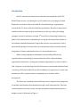
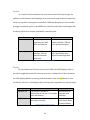
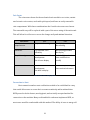
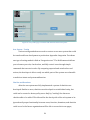
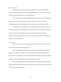
Share Jar: Integrating Charity into Everyday Life Mark Khazanov CpE-‐499: Capstone Design Project Advisors: Cherrice Traver, Kristina Striegnitz March 8, 2015 Abstract While American wealth continues to grow, income inequality and the wealth gap have never been a more pertinent issue in the United States. While legislative change is difficult to attain and service to community depends mainly on people’s availability, systems of monetary donation have not changed for decades aside from web based payment systems. We propose a new donation collection system that allows for easier charity access and integration of charitable giving into daily routine. The proposed coin collectors can be installed in public spaces and will allow users to donate and distribute funds within thirty seconds to various charities through an online account. Furthermore, integration with social media services such as Facebook and Twitter will also be emphasized in our approach. We conclude with an overall design of our units and a discussion of possible marketing techniques and steps that will be taken to make our product a popular commodity. 2 Table of Contents ABSTRACT ................................................................................................................................................ 2 TABLE OF FIGURES AND TABLES ..................................................................................................... 5 INTRODUCTION ...................................................................................................................................... 6 BACKGROUND ......................................................................................................................................... 7 COIN COLLECTION SYSTEMS ................................................................................................................................... 7 SIMILAR CHARITIES .................................................................................................................................................. 8 DESIGN REQUIREMENTS ................................................................................................................... 10 USER INTERFACE .................................................................................................................................................... 10 Hardware .............................................................................................................................................................. 10 Software ................................................................................................................................................................. 11 MAINTENANCE ........................................................................................................................................................ 12 Hardware .............................................................................................................................................................. 12 Software ................................................................................................................................................................. 13 PRELIMINARY PROPOSED DESIGN ................................................................................................ 15 SOFTWARE ............................................................................................................................................................... 15 HARDWARE ............................................................................................................................................................. 16 CONTROL .................................................................................................................................................................. 18 DISPLAY .................................................................................................................................................................... 18 COIN SORTER .......................................................................................................................................................... 19 CONNECTION TO HOST .......................................................................................................................................... 19 CONNECTION TO NETWORK ................................................................................................................................. 20 CASE .......................................................................................................................................................................... 21 COST .......................................................................................................................................................................... 22 CHANGES IN DESIGN SPECIFICATIONS ......................................................................................... 22 FINAL DESIGN AND IMPLEMENTATION ....................................................................................... 23 SYSTEM OVERVIEW ................................................................................................................................................ 23 PHYSICAL UNIT ....................................................................................................................................................... 24 Coin Sorter and Display Units ...................................................................................................................... 25 Arduino Microcontroller and RFID Reader ............................................................................................ 27 Arduino Ethernet Shield ................................................................................................................................. 29 DEPOSITS SERVER .................................................................................................................................................. 29 WEB SYSTEM ........................................................................................................................................................... 30 Structured Data .................................................................................................................................................. 30 Ruby on Rails ....................................................................................................................................................... 31 User System – Build ........................................................................................................................................... 32 User System – Testing ...................................................................................................................................... 34 Charities and Donations ................................................................................................................................. 34 Favorites ................................................................................................................................................................ 36 Cards and Deposits ............................................................................................................................................ 36 Connection to Server ........................................................................................................................................ 38 PERFORMANCE ESTIMATES AND RESULTS ................................................................................ 38 EXPECTATIONS AND RESULTS .............................................................................................................................. 38 PRODUCTION SCHEDULE .................................................................................................................. 40 PHYSICAL UNIT ....................................................................................................................................................... 40 3 DEPOSITS SERVER .................................................................................................................................................. 42 WEB SYSTEM ........................................................................................................................................................... 42 COST ANALYSIS .................................................................................................................................... 43 USER’S MANUAL ................................................................................................................................... 44 PHYSICAL UNIT ....................................................................................................................................................... 44 DEPOSITS SERVER .................................................................................................................................................. 44 WEB SYSTEM ........................................................................................................................................................... 45 DISCUSSION AND RECOMMENDATIONS ....................................................................................... 45 REFERENCES .......................................................................................................................................... 47 APPENDIX .............................................................................................................................................. 48 4 Table of Figures and Tables Figure 1: Proposed design of the full unit. ...................................................................................... 7 Figure 2: Proposed method of selecting donation amount. .................................................. 12 Figure 3: Removable tray for easy collection of deposited funds. ..................................... 13 Figure 4: A mockup Share Jar icon used for monetary donation on various websites.
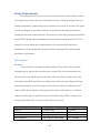
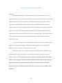
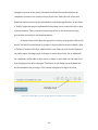
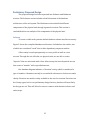
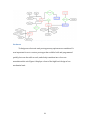
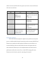
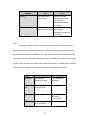
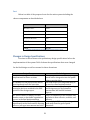
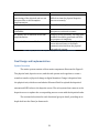
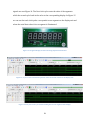
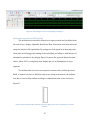
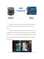
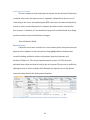
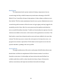
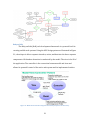
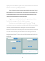
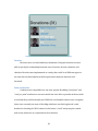
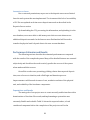
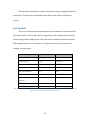
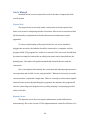
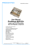
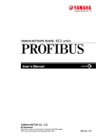
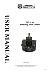
............................................................................................................................................................... 14 Figure 5: High-‐level design of the Share Jar mechanical unit. ............................................. 17 Figure 6: High level user process of the Share Jar donation system. ................................ 17 Table 1: Cycle time for each hardware component. ................................................................. 11 Table 2: Controller design options. ................................................................................................. 18 Table 3: Display design options ........................................................................................................ 18 Table 4: Coin sorter design options. ............................................................................................... 19 Table 5: Connection to host design options. ................................................................................ 20 Table 6: Connection to network design options. ....................................................................... 21 Table 7: Case materials design options. ........................................................................................ 21 5 Introduction In 2013, statistics on charity were collected from around the world. The United States was not even among the top 10 countries for percentage of citizen donations. It is hard to believe that with all of the philanthropic organizations started in the U.S. we are still far behind the top donators. But what is important to consider is that the same study showed that we are the top country for helping strangers in need of assistance and rank 3rd overall for volunteering (cafamerica) (Hall). Clearly Americans are philanthropic, so why has the United States fallen so far behind in charitable donations? I argue that there are two main issues: lack of passion and empathy for charities that are well publicized (Stern) and the limited integration of charity opportunities into our current infrastructure. While creating empathy in individuals is an incredibly difficult task, especially when a potential giver does not have the will to explore donation opportunities themselves, creating more donation opportunities is a more realistic task. I propose a new technology that will allow users to donate and distribute funds to a variety of charities within 30 seconds. In addition, no registration or credit card information will be required, and no commitment post donation will be necessitated. The “Share Jar” donation system will allow users to deposit loose change into a container and distribute their donation through a web-‐based interface. The units can be installed at the end of check out lanes and public transportation systems. A design concept is illustrated in Figure 1. 6 Though the physical components are integral to the Share Jar approach to charity integration, they are not the main draw of our system. Social media has had tremendous affects societally, impacting culture in unimaginable ways. We have technology that allows us to post, share, like, rate, chat, message, transfer money, fund projects, and interact with the world in ways that were previously impossible. Each mentioned technology is branded: Facebook, Twitter, Tumblr, Kickstarter, Indiegogo, and many more. Surprisingly, the act of giving is still decentralized, lacking a cohesion that could benefit millions across the globe. Figure 1: Proposed design of the full unit. The Share Jar donation system is social media for charity. Lowering the donation time to less than 30 seconds and creating a daily reminder of giving, this technology is not only a step on the philanthropic ladder, but also a pivot for transition into a donation oriented society. Background Coin Collection Systems Currently, the most prominent coin collection system is Coinstar, located all across the United States. Users are able to deposit coins and receive gift cards, 7 eCertificates, and cash. With gift cards and eCertificates users are not charged for the transaction. Cash back has a 10.9% coin-‐processing fee. Users are also able to donate to a few select charities, but participating organizations are fined 7.5% of the users donation (Coinstar). We are attempting to provide charities with 100% of donations. From the users pocket to the charities account no funds will be deducted. Also, our system will be compatible with any charity that is web accessible and certified. This will allow local charities as well as small non-‐profit organizations to receive greater advertisement, support, and funding. While our system will only register credible charities at its inception (Cross), we hope to extend the opportunity to register to anyone who chooses once proper security measures have been taken. A possible “People” section may be created to sponsor homeless individuals living in a user’s local area. This will allow people to impact individuals as opposed to corporations if they empathize more with personal giving. Similar Charities The charity that is most similar to our own is the Salvation Army. Their yearly efforts to collect spare change from pedestrians is what our organization hopes to do with a mass distributed electronic platform that gives donators greater control over the charities they fund. The Salvation Army employees bring back the red bins to a central location and sort out bills from change. Both types of currency are sorted with industrial machines and the funds are then deposited in the company’s bank account. 8 Percentages of the collected amount are distributed among the central corporation and the specific branch responsible for collecting the funds. Removing collection agents from the equation, our process will be much more effective, allowing us to manufacture multiple units for a fraction of the cost of paid employees. Also, users will be able to choose the organizations they wish to donate too, Salvation Army included, and have greater control over their donation. The second charity that is similar does not collect change, but asks for donations when monetary exchanges are made in stores and facilities. UNICEF has specific tickets that they supply vendors with to offer customers. The customer can scan a ticket with their purchase and donate 1, 2, 5 or 10 dollars with their purchase. They can also choose to donate without the use of a ticket, which is a slightly longer process, but allows users to donate however much they choose. While this system is incredibly effective in digitizing charity, employees of the store where the system is implemented are still asked to scan tickets and ask each customer for a donation. Our attempt at collecting donations will include less work for both users and employees of our company. Our goal is to completely automate the system with several employees to manage account maintenance and several donation collectors and mechanics that can collect the funds, deliver them to banks, and transfer physical currency to the company’s online account. These changes will reduce barriers to charity significantly, decreasing work, increasing donation opportunity, and increasing user control over their donations. 9 Design Requirements The main goal of our project is to reduce the amount of time taken to donate to a charity and increase the ease of donation for users. This goal brings about our timing requirement: empowering users to donate in less than 30 seconds. The point of currency deposit to the time at which a user allocates the charity, should not extend past the mentioned time limit. The total cost of the first prototype should not exceed $1500 dollars. More information about expenses can be found in the “Cost Analysis” section. Below are requirements for the user interface and for the maintenance of the system. Each section has been separated into software and hardware requirements. User Interface Hardware A user will have two options when donating. They will be able to donate anonymously or register for an online user account. The donation machine will include a slot from which cards can be taken. Users will then be able to press the card against the RFID mechanism at which point a slot will open. Change will then be deposited and users will no longer need to interact with the hardware of our system. While the hardware of the system is far from revolutionary, it combines common technologies to produce fast, user-‐friendly results. Table 1 displays the timing requirements for each part of the hardware process. Component Slot Lid RFID Microcontroller and Wifi Entire system Function Open and Close Read Input Delay Send Signal to Database Scan, Deposit, Send Signal 10 Cycle Time 3 seconds 3.75 seconds < 0.25 seconds 3.75 seconds Table 1: Cycle time for each hardware component. Software Moving from hardware to software users will be presented with the two donation options. To access their personal accounts users will be asked to login with email and password. If users choose to donate anonymously they will be able to enter the card ID number with which they donated and distribute the funds. To create greater security, a 4-‐digit number will be included on the back of each card to serve as a security code. Entering the card and security numbers will be the only requirements for anonymous donators. After a confirmed login, users will be able to view the deposited amount, browse through charities, and select their desired donation amount. To increase user base in the “registered account” system, users will be able to combine accounts by selecting a “Merge Accounts” option and entering the ID numbers of two accounts to which they have a card. After users gain access to their accounts they will be able to distribute the donated funds. A user will be able to trace a line around a fraction of pie chart shown in Figure 2. They will then be able to click on a featured charity in the right panel of the webpage to which the selected amount will be donated. Users will also be able to search for registered charities. After a charity is selected a “Donate” button will become available at which time the user will be able to commit to their donation. 11 Figure 2: Proposed method of selecting donation amount. Maintenance Hardware To create the easiest system of money transfer our unit will need to be robust, easily accessible, and compartmentalized. The unit will be made from aluminum with an outer plexiglass barrier. A keyhole will be located on the bottom of the device. The bottom plate will be directly underneath the deposit tray and when pulled down the deposit tray can be removed and replaced with another tray. The removable tray mechanism is displayed in Figure 3. This will make collecting the deposited funds an easy and speedy process. 12 Figure 3: Removable tray for easy collection of deposited funds. While the prototype hardware will consist of hobbyist materials, such as the Arduino Uno and Parallax RFID, previous experimentation has shown the unreliability of these systems and while development of robust, low cost solutions my not be implemented, these necessary requirements will be strongly considered. Furthermore, the prototype design will be heavily modularized to allow for an easy transition from high-‐level prototyping to low level implementation of the electronic units. Software Our interaction with databases and transition of funds will be the greatest challenge in the system implementation. To make the process as easy as possible, only virtual funds will be associated with a user account. Physical funds will be collected and stored in a company account. For the first implementation of our system, the company will create an account for every online charity available 13 through its system. At the point of donation funds will be transferred from the companies account to the charity selected by the user. Share Jar will collect user donation statistics and relay this information to participating charities. In the future a “PayPal” approach may be implemented connecting user accounts directly to their selected charities. This is seen as a long-‐term goal due to the excessive security precautions necessary for this implementation. An integral part of the Share Jar approach to charity is integration with social media. The small icon will allow for people to donate without excessive hassle. Akin to Twitter, Facebook, RSS Feed, and YouTube icons, Share Jar will also be displayed on public pages, allowing people to donate to causes they see fit. For an additional fee, companies will be able to allow users to donate to their own site, but only if the icon is displayed on their webpages. This feature is still being researched and will not be included in the prototype. The concept is displayed in Figure 4 below. Figure 4: A mockup Share Jar icon used for monetary donation on various websites. 14 Preliminary Proposed Design The proposed design has been separated into Software and Hardware sections. The Software section includes a brief discussion of the database architecture of the web system. The Hardware section details the different components of the physical unit through a general overview. This section is concluded with a cost analysis of the components of the physical unit. Software To create a viable web system a drafted database scheme was first necessary. Figure 5 shows the completed database architecture. Included are six entities, two of which are considered “weak” due to their dependency on parent entities. A User entity is used synonymously as a user profile as well as a user account. Through the use of kiosks, our physical units, we are able to create “deposits” that are associated with a User. After money has been deposited we can then create a “transfer” with a specified amount. Our database diagram indicates a “donation” entity, which is considered a type of transfer. A donation can only be created with references to both a user and a charity. Favorites are another entity available to the user for creation. Favorites can be of many types, but for our preliminary design favorite_charities will most likely be the type we use. This will allow for users to connect with charities in faster and easier ways. 15 Figure 5: The web systems database architecture Hardware To design our electronic unit prototype many options were considered. It was important for us to create a prototype that could be built and programmed quickly, but was also able to scale, and slowly transition into a low cost manufacturable unit. Figure 6 displays a chart of the high-‐level design of our mechanical unit. 16 Figure 6: High-‐level design of the Share Jar mechanical unit. The process of designing the unit was fundamentally based on aligning functionality with mission. It was important to define a sequence of events that the user would step through while keeping the idea of “charity as a part of everyday life” central to the process. Figure 7 shows the high-‐level process our system was based on, providing maximum ease of donation. Figure 7: High level user process of the Share Jar donation system. 17 Control As a control unit the Arduino Uno was selected for the first prototype. Its ability to easily interface with displays, host connections, and network connections made it a top choice among microcontrollers. While the Raspberry Pi was another strongly considered option, it was difficult to interface with other technologies and would not allow for a realistic, minimalist, controller unit. Control arduino pros Easily programmable interfaces well with RFID and ethernet cons Very limited in terms of software abilities. Difficult to run parallel processes. raspberry pi Easily interfaces with Difficult to interface with ethernet. Can run RFID. Significantly more parallel processes difficult to prototype with. with ease. Table 2: Controller design options. Display For the display an LCD unit was selected. While the HEX display is able to provide enough information for the user to receive confirmation of their donation, the LCD display added a necessary professionalism to the unit. Addition of color would also allow for a vivid display that could present organization or charity logos. Display Standard LCD pros cons Can provide a breadth of More difficult to information for the user. Can include integrate with color and vibrancy. controller. Hex Display Easily understandable. Integrates easily with controller. Table 3: Display design options 18 Conveys less information. Quite limited in display. Coin Sorter The coin sorter chosen for the mechanical unit needed to sort coins, contain an electronic coin counter, work with quick speed, and have an easily removable coin compartment. With these considerations the Cassida coin sorter was chosen. The removable tray will be replaced with a part of the outer casing of the entire unit. This will allow for collectors to access the change easily and minimal intrusion. Coin Sorter Mechanical napcoinsorter pros Very accurate sorting cons No display No counting kanection Can separate coins efficiently No counting provided No display Royal Sovereign Counts without need for development Has it's own display Includes finite cointainers that are difficult to modify Cassida Counts without need for development Has built in display Slower coin processing then mechanical sorters Table 4: Coin sorter design options. Connection to Host Host connection and account verification needed to be established in a way that would allow users to access their accounts seamlessly and in minimal time. RFID proved to be the fastest, most hygienic, and societally accepted method for connection to the machine. Many credit and debit cards now implement RFID, so most users would be comfortable with this method. The ability of users to merge old 19 and new accounts would also allow for people to just retrieve a new card whenever theirs were not with them. Connection to Host RFID pros No need to remove card from pocket Fastest Method No need for pin cons Card can be lost Can interfere with other RFID cards Can get stolen Magnetic Swipe No need to remember pin Magnetic Strip will ware down Can lose card Can get stolen Barcode No need to remember pin Can lose the card Barcode may ware off in pocket Can get stolen Pin Access No need to carry card around Takes time to enter pin No way to lose a card Can easily forget number Difficult to steal pin as Have to stop and think opposed to card Table 5: Connection to host design options. Connection to Network Due to the conversion of physical to digital currency and the account upload process, a reliable method of network connection was also necessary. Both WiFi and Ethernet were considered as viable options, but Ethernet was selected due to its increased reliability. Most stores that include electronic cash registers have the units connected to Ethernet ports, so the implementation of mechanical units in public places would not be an issue. Due to a lack of WiFi in many public areas, Ethernet was also the better option for connecting to the network. 20 Connection to Network Wired WiFi pros No need for wifi connection cons Wires in the way Need ethernet port on controller Need ethernet port in location No need for Need wifi component ethernet connection to controller Need wifi connection in building Table 6: Connection to network design options. Case Creating a durable casing that was secure and easily accessible was also a large consideration. Aluminum casing was chosen for the prototype because of its professional look and its availability. It is also easier to work with than some of the other materials specified and would help convey a completed look for the prototype version of the mechanical system. Other materials would be considered for scalable units due to the expensive pricing of aluminum as compared to plastics. Case Aluminum pros Metallic and professional look cons Can bend easily Expensive Carbon Fiber Very strong material and looks great Expensive Steel Very strong material Plastic Inexpensive and easily produced Expensive Not easily customizable Weaker material Table 7: Case materials design options. 21 Cost Below is a table of the proposed costs for the entire system including the chosen components as described above. Item Cost Metallic Case: $300 Coin Counter: $200 Microcontroller: $50 Wireless Module: $30 RFID Detector: $50 3rd Party Software: $500 Total: $1130 Table 8: Estimated cost of components for the entire system. Changes in Design Specifications Previous to this section are the preliminary design specifications before the implementation of the system. Table 9 shows the specifications that were changed for the final design as well as reasons for these alterations. Design Change Social media integration will be implemented in future versions A container for the physical unit will be developed and used at a later time Discussion of business and marketing strategies has been avoided in the final portion of the design report Methodology The web system needs to be completely tested before integration into the public sphere can take place The coin sorter is too large and bulky to be used as a final implementation Chose to focus more on the engineering and design aspects. My Steinmetz presentation will include business aspects. No actual transfer of money to either This is a component of the business side bank account or charitable organization and what is most effective, scalable, and occurs in the final implementation efficient The user interface for donating differs A more “playful” UI was distracting and significantly in the final version, allowing took away from the goal of quick users to just type in an amount and click donations 22 “Donate” Detailed timing values for the functioning of the physical unit are not discussed due to an incomplete implementation Unregistered cards have been eliminated Merging of user accounts has been eliminated No display will be featured in the final implementation A Deposits Server was added Due to the lack of full functionality it was difficult to time the physical deposits process accurately Too difficult to implement at this point This was done due to the removal of anonymous cards and accounts A display is not necessary. The only user feedback should be green and red LEDs for purposes of simplicity Due to system permissions a deposits server was necessary to facilitate communication between the physical unit and web system Table 9: Design specification changes from proposed design to implementation. Final Design and Implementation System Overview The entire system consists of three main components illustrated in Figure 8. The physical unit, deposits server, and the web system work together to create a seamless transfer of physical change to digital donation. Change is deposited into the physical unit, which uses an Arduino Ethernet Shield to upload the deposited amount and RFID value to the deposits server. The web system then connects to the deposits server to update the corresponding users account with the deposited value. The sections below describe each functional group in detail, providing an in-‐
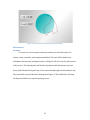
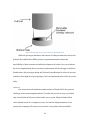
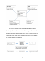
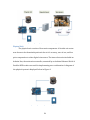
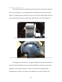
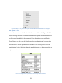
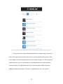
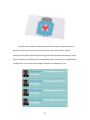
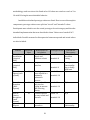
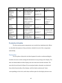
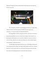
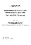
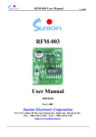
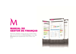
depth look into the Share Jar framework. 23 Figure 8: High level graphic of the entire prototype system. Physical Unit The physical unit consists of four main components. A Cassida coin sorter was chosen to be the main deposit unit due to it’s accuracy, ease of use, and low price comparative to other digital coin sorters. The inner electronics included an Arduino Uno, the main microcontroller, mounted by an Arduino Ethernet Shield. A Parallax RFID reader was used for implementing user confirmation. A diagram of the physical system is displayed below in Figure 9. Figure 9: High level diagram of the physical unit. 24 Coin Sorter and Display Units The Cassida coin sorter included a geared funnel that would control the flow rate of currency Figure 10, a rotating disk that would drop coins into slots by size Figure 11, triggering sensors attached to the rim of each slot, and a display unit that was updated by the electronic components within the base of the unit Figure 12. Figure 10: Geared component of coin sorter used for controlling flow of currency. Figure 11: Rotating tray for processing change. Each hole contains a sensor for tracking the amount of change deposited. The display unit consisted of 7, 8-‐segment displays. Serial data was passed to the board and each display was consecutively updated in a continuous cycle when triggered by a clock pulse. Figure 13 shows two consecutive display uploads. Zooming in we are able to see that for each display two rounds of 8-‐pulse clock 25 signals are sent Figure 14. The first clock cycle resets the value of the segments while the second cycle loads in the value to the corresponding display. In Figure 15 we can see that each clock pulse corresponds to one segment on the display unit and when the serial data value is low a segment is illuminated. Figure 12: 8-‐segment display used for retrieving deposited amount data. Figure 13: 2 cycles can be seen which represent consecutive loads of values to the display unit. Figure 14: An 8-‐pulse clock cycle used for loading data to each segment of one display. 26 Figure 15: The loading of a value corresponding to the digit 5. Arduino Microcontroller and RFID Reader The Arduino microcontroller allowed us to capture serial and clock data from the coin sorter’s display. Appendix: Read Serial Data shows how serial data was read using the Arduino’s SPI capabilities. By setting our clock signal as an interrupt, each clock pulse would trigger the reading of the serial data, providing us with the byte of information uploaded to the display. Figure 16 shows the captured data as decimal values, where 255 is a completely dark display and 0 is an illumination of every segment. The Arduino and coin sorter were paired as master slave with the preset of MOSI, or master out slave in. With the coin sorter acting as the master, the arduino was able to receive data without needing to communicate back to the coin sorter Figure 17. Figure 16: Raw byte data taken from the coin sorter display. The value corresponds to a 0 with a decimal. 27 Figure 17: A diagram of the arduino and coinsorter represented in an SPI master-‐slave relationship. Appendix: Convert shows the coded process for converting the captured bytes of data into the human readable digits that could be uploaded to user accounts. The RFID reader was connected to the Arduino, which would wait until a valid RFID value was read to begin the display reading, conversion, and upload processes. Due to serious hardware issues the RFID unit was not implemented in this version of the prototype, but future versions will continue to use an RFID verification system. Figure 18: The connected RFID unit. Not implemented in the final design due to faulty hardware. 28 Arduino Ethernet Shield The last component used in the physical system was the Ethernet Shield used to upload values onto the deposits server. Appendix: Upload shows the process of connecting to the server and uploading the RFID card values, the amount deposited, as well as other crucial information to complete the online transfer from kiosk to user account. A “machine_id” was included to keep track of which kiosks were being used most often for future distribution strategies. -‐Uno to Ethernet Shield Deposits Server A deposits server was created to act as the transfer point of deposits from the physical unit to updates on the web system. Using phpMyAdmin a database was created including attributes such as card_number, deposited_amount, and machine_id Figure 19. The current implementation creates a CSV file from the uploaded data, which can then be read by the web system. This process is inefficient and impractical, so future transfers will eliminate the deposits server and upload transaction data directly the web systems database. Figure 19: phpMyAdmin screenshot displaying attributes in the deposits server database. 29 Web System The implemented web system consisted of many components, but was created using the Ruby on Rails framework, which takes advantage of the MVC (Model, View, Controller) software design pattern. A data scheme architecture was first drafted. The first entity implemented was the user system. Administrators were created along with sessions to allow for users to login, signup, and stay logged in for extended periods of time. After the user system was thoroughly tested charities were created followed by donations. To add user functionality the option to favorite charities was added so that users could connect with organizations even faster. The final entities created were deposits and account cards were added to the user data scheme. The final step was to connect the web system to the deposits server, so a program was written to upload the CSV file found on the deposits server into the system’s database, updating each user’s profiles. Structured Data Through consideration of the entire web system a flexible data scheme was drafted that could then be implemented. With 6 distinct entities I was able to formulate a structure of relationships and associations that would allow for a scalable model that could be easily altered in the future. Figure 20 shows the entities, associations, and important attributes featured in the design. 30 Figure 20: Final database architecture used for web system implementation. Ruby on Rails The Ruby on Rails (RoR) web development framework is a powerful tool for creating scalable web systems. Using the MVC design pattern as illustrated in Figure 21, a developer is able to separate interface, action, and data into the three separate components. All database alteration is conducted by the model. The view is the UI of the application. The controller is the connection between model and view and allows for powerful control of the entire web system and its implemented entities. Figure 21: Model View Controller diagram taken from (UI Software Architecture). 31 Figure 22: Ruby on rails project file layout. Controller, Model, and View folders are displayed. User System – Build A user system was built to include the user model found in Figure 23. Both signup and login features were added under the user system and an administrator attribute was later added to the user model. From the index of user profiles in Figure 24, we are able to see the list of users from an administrator’s perspective. Each user has a “delete” option next to their name. This is only present from the administrator’s view, indicating that only an administrator can delete users that are registered on the system. Figure 23: Completed User system model without any additional entities. 32 Figure 24: Complete users index. Delete option is presented due to administrator perspective. A user profile was created that displayed the user image using “Gravitars”, a built in Wordpress feature that allows users to easily upload profile pictures. The user’s balance was also displayed in the top left panel of Figure 25. The bottom left panel shows the user’s recent donations, including the amount donated and the selected charity. The right panel is the user’s favorites panel, which allows for adding an unlimited amount of “favorite” organizations to the user’s profile. 33 Figure 25: User profile page screenshot with donation and favorites panes. User System – Testing Various testing methods were used to create a secure user system that could be transferred from development to production. Appendix: Integration Test shows one type of testing method called an “integration test”. The RoR framework allows you to browse your site, check values, and fully control users through simple commands that execute in order. By comparing expected and actual values and actions, the developer is able to easily see which parts of the system are vulnerable to malicious intent and system malfunction. Charities and Donations After the user system was fully implemented a system of charities was developed. Similar to users, charities were developed as an individual entity, but could not be created or destroyed by users. Only by “seeding” the data were charities able to be added. This allowed for the charity side of the web system to be ignored until proper functionality between users, favorites, donations, and charities could occur. In the future organizations will be able to access their own pages, 34 upload pictures into slideshows, update content, and track the amount of donations that have occurred over a specified period of time. Figure 26 shows the charity browser page included on the website. The left panel includes the list of all charities with a search option for easy navigation. The top right panel includes a charity of the day with the donation statistics for that charity featured underneath in the bottom right panel. Logged in users can find charities, favorite the organizations, and donate from both their own page as well as the charity browser page. Donations were created using the concept of “associations”. Through associations we can create connections to multiple models. Both users and charities “had many” donations and donations “belonged to” both users and charities. Whenever a donation was created, the presence of a donation amount, a referenced user, and a referenced charity were all verified to ensure the legal creation of a donation instance. Figure 27 shows a close-‐up of the donations panel on the user’s profile page. Figure 26: Charity browser with charity navigator, charity of the day, and donation statistics panes. 35 Figure 27: A closer look at the donations pane on the user profile page. Favorites Favorites were created similarly to donations. Using associations we were able to specify the relationship between users, favorites, favorite_charities, and charities. Favorites was implemented as a entity that could be of different types in the case that our functionality would require more than just charities to be favorited. Cards and Deposits Cards were an easy addition to our user system. By adding “card_num” and “card_sec_num” attributes to our user model we were able to provide each user with a card that they could eventually use. While the card number values were encrypted, there were currently no ways of checking whether a user had registered a card besides for checking for NULL values. In the future a “card” entity may be created with a user reference as a requirement for activation. 36 Figure 28: Concept art for a user's deposit card. Deposits were similar to donations, but did not require a charity reference because they existed as sole property of the user. Users were able to deposit multiple times and see their deposits along with other pertinent information. In the future a database of machine_ids corresponding with locations will be implemented to allow users to see where their highest frequencies of deposits occur. Figure 29: List of user deposits. 37 Connection to Server Due to network permissions, my access to the deposits server were limited from the web system that was implemented. To circumvent this lack of accessibility a CSV file was updated each time a new deposit was made as described in the Deposits Server section. By downloading the CSV, processing the information, and uploading it to the user database, users were able to add money onto their account whenever an additional deposit was made. In the future a more fluid method will be used to transfer the physical unit’s deposit data to the user account database. Performance Estimates and Results The following sections describe the estimated performance as compared with the results of the completed system. Many of the detailed features are assessed subjectively and should not be used to strictly predict the success of the system when made available to users. Overall the results were promising, yielding a faster than expected deposit time, ease of access to charities, and a fluid login and donation process. Improvements could be made in areas of cost, aesthetics and size of the physical unit, and scalability of the hardware components. Expectations and Results The main goals of our project were to create an easily usable interface with a donation time of less than 30 seconds, and implementing a system that was extremely flexible and scalable. Table 10 shows the expected values, of each considered component before the completion of the project as well as the 38 methodology used to arrive at the listed value. All values are rated on a scale of 1 to 10 with 10 being the most desirable behavior. In addition calculated prototype values are listed. Due to several incomplete components, prototype values were split into “actual” and “intended” values. Participants were asked to rate the actual prototype for each category and then the intended implementation that was described to them. Values were based off of 5 individuals. Possible reasons for discrepancies between expected and actual values are also included. Feature Ease of Installation (physical unit) Ease of Use (physical unit) Expected Value 7 Methodology in Calculation Due to Ethernet chord, and bulkiness of unit Prototype Values Actual: 3 Intended: 8 9 Simple RFID interface Actual: 6 Intended: 9 Ease of Signup (web system) 10 Actual: 10 Intended: 10 Ease of Donation (Web System) 10 Ease of Charity Navigation (web system) Speed of Deposit 10 Creating new users should be a minimally exhaustive process Process should only involve typing in amount and selecting charity Charities should be easy to find and discover Less than 10 seconds to 9 39 Reasons for Discrepancy Incomplete hardware casing Incomplete functionality due to faulty RFID unit N/A Actual: 10 Intended: 10 N/A Actual: 10 Intended: 10 N/A Actual: 4 Physical unit’s functionality (physical unit) Speed of Donation (web system) Security (physical unit) Security (web system) Aesthetic Appeal (physical unit) Aesthetic Appeal (web system) 10 5 8 5 9 validate RFID and deposit change Users should only enter value and select charity Intended: 10 Expected that a properly secure container would not be created for this version Expected a properly tested web system Was aware that a container would not be created for this version Wanted to create a beautiful, fluid user experience Actual: 3 Intended: 8 Actual: 10 Intended: 10 Actual: 9 Intended: 10 Actual: 2 Intended: 7 Actual: 8 Intended: 9 was not fully complete N/A Physical unit was deconstructed at time of display N/A There was no container used for the physical unit N/A Table 10: Comparison of expected and actual results. Reasons for discrepancies are also listed. Production Schedule The three main system components were worked on simultaneously. Below are detailed descriptions of the production schedule for each of the components individually. Physical Unit The first phase of physical unit development focused on understanding the Cassida coin sorter and accessing the information it was passing to the display. The unit was disassembled and the display unit was extracted from the machine. The two-‐sided circuit board in Figure 30 was analyzed and a schematic was sketched from which functionality of the display could be further understood. 5 pins corresponding to the clock, serial data, and three pins for the display selector were 40 analyzed, allowing us to further understand the display data that was being sent from the coin sorter. Figure 30: Connected pins to coin sorter display for capturing of serial data. The second phase consisted of programming the Arduino to recognize RFID cards and validate users. Unfortunately, the RFID unit was too poor in its consistency, so it was not used for the final implementation. Following RFID accessibility, integration with the coin sorter was necessary. A program using SPI was written to allow for the reading of values from the coin sorter display by the Arduino microcontroller. In addition, a script was written to convert the byte values from the coin sorter display into human readable integers corresponding to a deposited amount. The final phase of development was the process of uploading to the deposits server using the Ethernet Shield. The Arduino would connect to the server, and post all values to a file located on the server, which would then process the values and insert them into the MySQL database located on the remote machine. 41 Deposits Server The first step in creating a functional deposits server was creating PHP scripts that could connect to the servers MySQL database, receive values from the Arduino, and insert those values into the database. After these files were written, phpMyAdmin was used to create the database that would be used for deposits information. Files were altered to include information specific to the database so that connection could become possible. The final phase of the deposits server implementation was the creation of a CSV file from the inserted data. Due to system permissions, this inefficient method had to be used to access deposit information from the web system. Future implementations will allow for direction connections between the kiosk units and the web systems databases. Web System The web system was first organized based on a database architecture that was both scalable and flexible [Figure 20]. After a completed data scheme a user system was implemented. Sessions, signups, and logins were added, soon followed by administrative privileges. The user system was completely tested using various RoR testing techniques, including integration tests as detailed in the earlier Web System section. Charities and Donations were created and soon a Favorites option was also implemented. This phase allowed users to donate to charities, favorite charities, and view their previous donations. 42 The last phase included the creation of deposits and processing the deposits server data. The process is described in more detail in the earlier Web System section. Cost Analysis The cost of components was nearly identical to estimated costs as described previously. Table 11 shows the various components, their estimated costs, and the actual pricing of the prototype unit. The total costs for estimated and actual values differ significantly due to the absence of 3rd party software and any protective casing for the prototype. Item Estimated Cost Actual Value Metallic Case: $300 NA Coin Counter: $200 $206.76 Microcontroller: $50 $25.29 Ethernet Shield: NA $11.11 Wireless Module: $30 NA RFID Detector: $50 $49.99 Domain Names and Hosting: NA $129.99 3rd Party Software: $500 NA Total: $1130 $423.14 Table 11: Cost analysis of the hardware components for the physical unit. NA values specify components that were removed from the preliminary design. 43 User’s Manual Included below is a user’s manual for each of the three components of the overall system. Physical Unit The physical unit is currently under construction and only requires that there is no excessive tampering with the electronics. After a case is constructed and full functionality is implemented a further discussion of maintenance can be appended. To achieve functionality of the physical unit the coin sorter should be plugged into an outlet, the Arduino should be connected to a computer, and the program titled “full_program.ino” needs to be executed. The coin sorter should then be turned on using the back switch at which point coins can be deposited into the spinning tray. The values will update automatically and will then be ready for conversion. Due to incomplete functionality, the conversion and upload program must be run separately and is titled “covert_and_upload.ino”. Whenever this script is run the converted value is uploaded a single time. There is currently no autonomous upload featured in the system. By uploading the program to the Arduino, the program will execute, connecting to the deposits server, calling “add.php” and posting specified values to the file. Deposits Server The deposits server does not require maintenance and should function autonomously. Due to the current CSV file implementation, a new file will have to be 44 downloaded whenever an additional deposit is made. This functionality will be removed in the next version, and is only a temporary measure. Web System The web system does not require maintenance and will function autonomously without user interference. New charities may be added through the “seeding” process, and the uploading of deposits data will occur autonomously, but only after the file has been moved into the specified directory. Discussion and Recommendations How do we begin to integrate charitable giving into everyday life? The current process of donation is time consuming, rarely accessible, and seen as an additional hassle in everyday life. By creating a system that is easily accessible, takes seconds to use, and provides users with the convenience of disposing of their change, we can begin to make charitable giving a daily habit for individuals across the world. Starting with a digital coin sorter, a physical unit was built to process user donations after RFID validations, and upload the deposited amount to an online database. A web system was designed to give users full access to a variety of charities, implementing a donation process that is as simple as entering an amount and pressing “Donate”. The hardware and software were connected through the deposits server, creating a usable system that could process deposited change and upload the amount to corresponding user accounts. While the functionality of the physical unit was not fully realized, the remainder of the system proved to be successful and up to par with initial 45 specifications. In future implementations of the system I would further develop the physical unit to be completed and enclosed within a secure container. I would also add more statistical information to the web system so that users and charitable organizations are able to see deposit and donation habits respectively. After a usable implementation of the system it will be important to monitor the use of kiosks in various environments. Where do people donate most, why do people choose not to use the system, which charities are being donated to most, and what are the easiest ways to transfer the physical currency from the Share Jar units to the bank accounts of the organizations? These will all be important questions moving forward. Working throughout this past year has taught me an immense amount about different technologies and systems. But the most important takeaway is that impactful technology is not rooted in design specifications. The details of implementation arise from reminding ourselves of the purpose of our mission: Creating a society that contributes without hesitation. 46 References "6.831 L3: UI Software Architecture." 6.831 L3: UI Software Architecture. Web. 17 Mar. 2015. "2013 World Giving Index." CAF America 2013 World Giving Index Comments. N.p., n.d. Web. 13 June 2014. <http://www.cafamerica.org/wgi-‐2013/>. "Arduino -‐ SPI." Arduino -‐ SPI. Web. 17 Mar. 2015. "Coinstar / Help Center." Coinstar / Help Center. N.p., n.d. Web. 13 June 2014. <https://www.coinstar.com/helpcenter>. Cross, Ian. "Check a charity's credibility before you give this season." -‐ WMBFNews.com, Myrtle Beach/Florence SC, Weather. N.p., n.d. Web. 13 June 2014. <http://www.wmbfnews.com/story/24112237/check-‐a-‐charitys-‐
credibility-‐before-‐you-‐give-‐this-‐season>. Hartl, Michael. Ruby on Rails 3 Tutorial: Learn Rails by Example. Upper Saddle River, NJ: Addison-‐Wesley, 2011. Print. Holly, Hall. "Americans Rank 13th in Charitable Giving Among Countries Around the World." The Chronicle of Philanthropy. N.p., n.d. Web. 13 June 2014. <http://philanthropy.com/article/Americans-‐Rank-‐13th-‐
in/143349?cid=megamenu>. Stern, Ken. "Why the Rich Don't Give to Charity." The Atlantic. Atlantic Media Company, 20 Mar. 2013. Web. 13 June 2014. <http://www.theatlantic.com/magazine/archive/2013/04/why-‐the-‐rich-‐
dont-‐give/309254/>. 47 Appendix -‐-‐-‐-‐-‐-‐-‐-‐-‐-‐-‐-‐-‐-‐-‐-‐-‐-‐-‐-‐-‐-‐-‐-‐-‐-‐-‐-‐-‐-‐-‐-‐Read Serial Data-‐-‐-‐-‐-‐-‐-‐-‐-‐-‐-‐-‐-‐-‐-‐-‐-‐-‐-‐-‐-‐-‐-‐-‐-‐-‐-‐-‐ #include "pins_arduino.h" #include <Ethernet.h> #include <SPI.h> #include <SoftwareSerial.h> #define RFID_READ 0x01 #define txPin 6 #define rxPin 8 // what to do with incoming data byte command = 0; //Display pins int a0pin = A0; int a1pin = A1; int a2pin = A2; byte fullData[20]; volatile int i = 0; void setup (void) { Serial.begin(9600); // have to send on master in, *slave out* pinMode(MOSI, INPUT); SPI.setDataMode(SPI_MODE3); //digitalWrite(SS, LOW); // turn on SPI in slave mode SPCR |= _BV(SPE); // turn on interrupts SPCR |= _BV(SPIE); } // end of setup // SPI interrupt routine ISR (SPI_STC_vect) { 48 byte c = SPDR; if (i < 20){ fullData[i] = c; i++; } } // end of interrupt service routine (ISR) SPI_STC_vect void loop (void) { for(int j = 0; j<20; j++){ Serial.println(fullData[j]); //Serial.println("-‐-‐-‐-‐"); } // if SPI not active, clear current command //if (digitalRead (SS) == HIGH) //command = 0; } // end of loop -‐-‐-‐-‐-‐-‐-‐-‐-‐-‐-‐-‐-‐-‐-‐-‐-‐-‐-‐-‐-‐-‐-‐-‐-‐-‐-‐-‐-‐-‐-‐-‐-‐-‐-‐-‐-‐-‐Convert -‐-‐-‐-‐-‐-‐-‐-‐-‐-‐-‐-‐-‐-‐-‐-‐-‐-‐-‐-‐-‐-‐-‐-‐-‐-‐-‐-‐-‐-‐-‐-‐-‐-‐-‐-‐ byte high = B11111111; byte zero = B11000000; byte one = B11111001; byte two = B10100100; byte three = B10110000; byte four = B10011001; byte five = B10010010; byte six = B10000010; byte seven = B11111000; byte eight = B10000000; byte nine = B10011000; byte decimal= B01111111; byte fullData[30]; void setup(){ Serial.begin(9600); for(int j = 0; j < 18; j++){ fullData[j] = high; } fullData[16] = high; 49 fullData[17] = high; fullData[18] = high; fullData[19] = high; fullData[20] = decimal; fullData[21] = high; fullData[22] = one; fullData[23] = high; fullData[24] = five; for (int j = 25; j<30; j++){ fullData[j] = high; } } void loop(){ float number = process(fullData); Serial.println(number); } float process(byte data[]){ String number = ""; for (int i = 0; i < 30; i++){ if ((data[i] == decimal) && (i > 15)){ number += convert(data[i-‐8]); number += convert(data[i-‐6]); number += convert(data[i-‐4]); number += convert(data[i-‐2]); number += convert(data[i]); number += convert(data[i+2]); number += convert(data[i+4]); return number.toFloat(); } } } String convert(byte byteValue){ if (byteValue == high){ //Serial.println("True high"); return "0"; } if (byteValue == zero){ 50 //Serial.println("True 0"); return "0"; } if (byteValue == one){ //Serial.println("True 1"); return "1"; } if (byteValue == two){ //Serial.println("True 2"); return "2"; } if (byteValue == three){ //Serial.println("True 3"); return "3"; } if (byteValue == four){ //Serial.println("True 4"); return "4"; } if (byteValue == five){ //Serial.println("True 5"); return "5"; } if (byteValue == six){ //Serial.println("True 6"); return "6"; } if (byteValue == seven){ //Serial.println("True 7"); return "7"; } if (byteValue == eight){ //Serial.println("True 8"); return "8"; } if (byteValue == nine){ //Serial.println("True 9"); return "9"; } if (byteValue == decimal){ //Serial.println("True ."); return "."; } return ""; 51 } -‐-‐-‐-‐-‐-‐-‐-‐-‐-‐-‐-‐-‐-‐-‐-‐-‐-‐-‐-‐-‐-‐-‐-‐-‐-‐-‐-‐-‐-‐-‐-‐-‐-‐-‐-‐-‐-‐Upload -‐-‐-‐-‐-‐-‐-‐-‐-‐-‐-‐-‐-‐-‐-‐-‐-‐-‐-‐-‐-‐-‐-‐-‐-‐-‐-‐-‐-‐-‐-‐-‐-‐-‐-‐-‐ void loop(){ card = 432; //RFIDread(); card_sec = (int) 1324; amount = (float) 0.15; machine_id = (int) 100; data = "card=" + String(card) + "&card_sec=" + String(card_sec) + "&amount=" + String(amount) + "&machine_id=" + String(machine_id); if (upload && client.connect(server, 80)) { // REPLACE WITH YOUR SERVER ADDRESS Serial.println("Connected"); client.println("POST /add.php HTTP/1.1"); client.println("Host: khazanom-‐vm.union.edu"); // SERVER ADDRESS HERE TOO client.println("Content-‐Type: application/x-‐www-‐form-‐urlencoded"); client.print("Content-‐Length: "); client.println(data.length()); client.println(); Serial.println(data); client.print(data); } else{ //Serial.println("Can't connect"); } if (client.connected()) { client.stop(); // DISCONNECT FROM THE SERVER } upload = false; } -‐-‐-‐-‐-‐-‐-‐-‐-‐-‐-‐-‐-‐-‐-‐-‐-‐-‐-‐-‐-‐-‐-‐-‐-‐-‐-‐-‐-‐-‐-‐-‐-‐-‐-‐-‐-‐-‐Integration Test -‐-‐-‐-‐-‐-‐-‐-‐-‐-‐-‐-‐-‐-‐-‐-‐-‐-‐-‐-‐-‐-‐-‐-‐-‐-‐-‐-‐-‐-‐-‐-‐-‐-‐-‐-‐ 52 53