1
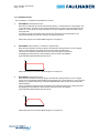
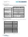
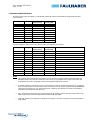
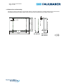
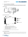
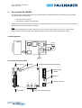
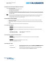
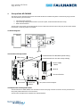
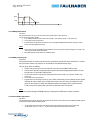
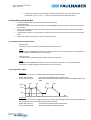
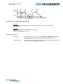
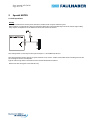
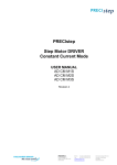
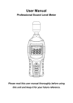
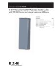
Stepper Motor DRIVER
Constant Current Mode
USER MANUAL
AD CM M1S
AD CM M2S
AD CM M3S
User manual AD CM M
Page 2 of 20
Release tracking
File
Description
V4900UM240904_CD
first tracked version
24.09.2004
Date
V4900UM240205_DC
Release with new product
24.02.2005
V4900UM051005_CD
Updated PIN-out info and safety notice
05.10.2005
V4900UM241105_CD-R1
Correction of optional cable part number
24.11.2005
V4900UM161205_CD-R2
Correction of suitable motors
16.12.2005
V4900UM210706_CD-R3
Protection rating added, M2.5 screw correction
21.07.2006
V4900UM080408_CD-R4
Name Update Precistep
08.04.2008
V4900UM280611_CD-R5
Update of complete user manual
28.06.2011
V4900UM300611_CD-R6
Correction of the MOTOR connection pins
30.06.2011
V4900UM010911_CD-R7
Update of pin logic, jumper CK completion
01.09.2011
V4900UM280812_CD-R8
Update of board dimensions
28.08.2012
Product denomination key
Typical Product type AD CM M1S
AD
Driver product category
C
Constant Current driver
M
Mode
M1
Function Mode
M1 = Pulse + direction drive, external control
M2 = Speed control drive w/o speed ramp (non-standard)
M3 = Speed control drive with speed ramp
S
External connection type
S
= Screw type for all connectors
Support
You may inquire with your questions about the software or the driver by e-mail or directly with your sales office. It is in
any case helpful to include the files you try to work with as well.
The e-mail contact address is:
[email protected]
User manual AD CM M
Page 3 of 20
Contents
1.
GENERAL INFORMATION ......................................................................................................................................................................................... 4
1.1
PRODUCT DESCRIPTION ...................................................................................................................................................... 4
1.1.1 Available versions......................................................................................................................................................... 5
1.2
TECHNICAL SPECIFICATIONS ................................................................................................................................................ 6
1.3
PROTECTION OF INPUTS AND OUTPUTS ................................................................................................................................. 6
1.4
SUITABLE PRECISTEP MOTORS .......................................................................................................................................... 7
1.5
DIMENSIONS AND MOUNTING ............................................................................................................................................. 8
2
SET-UP AND INSTALLATION OF AD CM M1S ............................................................................................................................................................ 9
2.1
BLOCK DIAGRAM .............................................................................................................................................................. 9
2.2
LOCATION OF COMPONENTS ............................................................................................................................................... 9
2.3
CONNECTION OF THE DRIVES ............................................................................................................................................... 9
2.3.1 COMMAND connector ................................................................................................................................................ 10
2.3.2 Switch for operation mode ......................................................................................................................................... 12
2.3.3 LED busy (near COMMAND connector) ...................................................................................................................... 13
2.3.4 Motor A/Power Supply + Motor ................................................................................................................................ 13
2.3.5 Current setting, rotary switch (potentiometer) .......................................................................................................... 13
3
SET-UP OF THE AD CM M2S ................................................................................................................................................................................... 14
3.1
BLOCK DIAGRAM ............................................................................................................................................................ 14
3.2
LOCATION OF COMPONENTS ............................................................................................................................................. 14
3.3
ADJUSTMENT OF THE SPEED, FMIN POTENTIOMETER ............................................................................................................ 15
3.4
OPERATION OF THE AD CM M2S ...................................................................................................................................... 15
3.4.1 Jumper ADJ = Adjust ................................................................................................................................................... 15
3.4.2 Jumper VCO = Voltage Controlled Oscillator .............................................................................................................. 15
3.4.4 Jumper CK = Clock ...................................................................................................................................................... 15
4
SET-UP OF THE AD CM M3S ................................................................................................................................................................................... 16
4.1
BLOCK DIAGRAM ............................................................................................................................................................ 16
4.2
LOCATION OF COMPONENTS ............................................................................................................................................. 16
4.3
ADJUSTMENT OF THE SPEED PROFILE .................................................................................................................................. 16
4.3.1 FMIN potentiometer .................................................................................................................................................. 17
4.3.2 FMAX potentiometer .................................................................................................................................................. 17
4.3.3 ACC and DEC Adjustment ........................................................................................................................................... 17
4.4
OPERATION OF THE AD CM M3S ...................................................................................................................................... 18
4.4.1 Switches/buttons RUN and STOP ............................................................................................................................... 18
4.4.2 Jumper ADJ = Adjust ................................................................................................................................................... 18
4.4.3 Jumper VCO = Voltage Controlled Oscillator .............................................................................................................. 19
4.4.4 Jumper CK = Clock ...................................................................................................................................................... 19
5
SPECIAL NOTES ..................................................................................................................................................................................................... 20
5.1
PULL-UP RESISTOR ........................................................................................................................................................... 20
User manual AD CM M
Page 4 of 20
1.
General Information
1.1 Product Description
The main interest of the use of a current mode driver such as the AD CM models is the current control
independent from the supply voltage (chopper). This allows to apply a much higher voltage than needed to
drive the current without risk of overheat.
It leads to a more constant torque output of the motor and increases the maximal speed plus gives the
possibility to boost the current if necessary.
The drivers AD CM M_S are specifically designed to control the phase current in current mode operation of
PRECIstep two phases stepper motors.
They offer:
• Full- and half-step operation
• Current control (preset currents – 16 levels of 50mA each)
• BOOST – current increase to 135% of set current level
• One-phase ON, two-phase ON operation (switch selection)
• STANDBY – activate or deactivate phase current to save energy
• INHIBIT – activate or deactivate phase current to save energy
• DISABLE- current is set to zero (windings open/shorted)
• STANDBY – current decay to 37% of set current level
Safety Note
DO NOT
Connect motor phase outputs A+, A-, B+, B- to positive supply
voltage input V+.
This will cause fatal damage to the driver.
AVOID
Connecting and disconnecting the motor from the driver while it
is powered on.
SWITCH OFF
Power when the motor is not operating to avoid overheating or
activate the STANDBY input of the driver.
User manual AD CM M
Page 5 of 20
1.1.1 Available versions
The AD CM M_S is available in three different versions
1)
AD CM M1S (Standard stock item)
Basic driver, requiring only clock and direction signals, it is destined to be controlled by a PC
or any other host. A switch on the board enable the user to choose manually between one
phase-on or two phase-on mode, clockwise or counter clockwise rotation and full or half
step operation.
It is able to control the position of the rotor shaft. Note that any speed profile can be
obtained depending on the host used for controlling the driver.
Please refer also to the “Product Block Diagram” in chapter 2.1.
2)
AD CM M2S (Non-Standard – available on request only)
Basic drive AD CM M1S including a plug-in board with a pulse generator to run a stepper
motor at a fixed speed. The speed is set manually with a potentiometer.
This version is good for speed control in start-stop mode (pull-in) operation.
Unplugging the blue jumpers will transform the unit into the AD CM M1S.
Typical speed profile possible with this driver:
v
t
Please refer also to the “Product Block Diagram” in chapter 3.1.
3)
AD CM M3S (Standard stock item)
Basic drive AD CM M1S including a plug-in board with a pulse generator to run a stepper
motor with a trapezoidal speed profile starting/stopping at a given frequency. The start/stop
frequency, maximum frequency, acceleration/deceleration time can be set manually with
potentiometers.
This is a standalone stepper motor controller mainly used for bench tests or demonstrators.
Unplugging the blue jumpers will transform the unit into the AD CM M1S.
Typical speed profile possible with this driver:
v
t
Please refer also to the “Product Block Diagram” in chapter 4.1.
User manual AD CM M
Page 6 of 20
1.2 Technical Specifications
As the AD CM M_S is a Current Mode Driver, the current level is preset by on-board switches with steps of 50mA.
It is designed to drive the small stepper motors in full step or half step, one phase-on or two phase-on, clockwise
or counter clockwise.
AD CM M1S
Power supply voltage
Min
Max
Power supply current
AD CM M2
V
8
32
mA
13
AD CM M3S
Motor Output current
max.
mA
750
Output current setting
0...15
mA
Can be set in 16 steps of 50mA
from 0 to 750mA
Logic input level
low
high
V
0 to 0.6 (+10% max)
2.5 to 28
Direction of rotation
cw/ccw
Step mode
full step (one phase ON or two phase ON)
half step (one phase ON)
Step frequency (speed)
Min
max.
Dimensions
full
step/s
0
---
10*
6000
10*
6000
mm
83.2x53.5x12
83.2x53.5x21
83.2x53.5x21
* If using the internal clock generator
1.3 Protection of Inputs and Outputs
The AD CM M_S versions are offering increased protection levels for the inputs and outputs as presented in the
list below.
Driver output short-circuit
AD CM M_S
Driver OUT
versus
GND
Driver OUT
versus
V+
Driver OUT
versus
Pin 1-2
Driver OUT
versus
Pin 1-3
Driver OUT
versus
Pin 1-4
Driver OUT
versus
Pin 2-3
Driver OUT
versus
Pin 2-4
Driver OUT
versus
Pin 3-4
Protection on COMMAND
☺
☺
☺
☺
☺
☺
☺
protected
not protected
protected
protected
protected
protected
protected
protected
AD CM M_S
Inputs
versus
V+
Inputs
versus
GND
Outputs
versus
V+
Outputs
versus
GND
Pin +5V
versus
GND
☺
☺
☺
protected
protected
not protected
protected
not protected
Note
If one of the non protected events occurs, the driver will be damaged.
User manual AD CM M
Page 7 of 20
1.4 Suitable PRECISTEP Motors
The driver of the series AD CM M_S is specifically suitable for motors with windings designed for constant
current control.
Motor Type
Winding
Current setting
Voltage setting
(switch position)
(recommended)
AM0820
V-3-18
AM1020
A-0,25-8
5
12 V
V2
6
10 V
ADM1220(S)
ADM1220(S)
3
16 V
V3
4
15.5 V
AM1524
A-0,25-12,5
5
18.5 V
AM1524
A-0,45-3,6
9
10 V
AM1524
V-6-35
3
27 V
AM2224(-R3)
AV-4,8
10
14.5 V
AM2224(-R3)
AV-18
5
27 V
For other stepper motors, the current control mode is possible but not optimal.
Motor Type
Winding
Current setting
Voltage setting Notes
(switch position)
(recommended)
ADM0620
V3
1
10 V
ADM0620
V6
-
-
AM0820
V-5-56
1
17 V
AM0820
A-0,225-7
4
10 V
12% torque reduction
AM1020
V-3-16
3
14.5 V
17% torque reduction
AM1020
V-6-65
1
19.5 V
45% torque reduction
AM1020
V-12-250
-
-
ADM1220(S)
V6
1
14.5 V
ADM1220(S)
V12
-
-
AM1524
V-12-150
-
-
AM2224(-R3)
AV-0,9
15 (max)
10 V
AM2224(-R3)
AV-12-75
-
-
33% torque reduction
Definitely not recommended for current mode
38% torque reduction
Definitely not recommended for current mode
45% torque reduction
Definitely not recommended for current mode
Definitely not recommended for current mode
35% torque reduction
Definitely not recommended for current mode
Notes
•
The settings of the second table use a lower current than the nominal current recommended in the
datasheet (that is why torque is reduced in most cases). It is possible to set a higher current but the
temperature may rise very quickly causing irreversible damages to the motor.
•
It is often possible to set the current to a close matching value by using the boost function. The idea is
then to set the current to a lower value and increase it up to 135% by using the PIN7 of the COMMAND
connector (see section 2.3.1 for more information). However, this solution is not direct and requires
controlling externally the boost function.
•
Also, when the current setting is not appropriated to the winding, please note that some motors may
offer a reduced operational speed because of their high back-EMF.
•
Generally speaking, the higher the voltage of the supply is, the more torque the motor will develop at
high speed.
User manual AD CM M
Page 8 of 20
1.5 Dimensions and mounting
The drivers can be mounted by using the four holes on the board. However, the M2 and M3 consist of two boards
assembled through these holes, which means that you have to fix the driver by using 4 screws M2.5.
14.2
52
53.5
4x M2.5 x 5.3
53.5
48.0
4x O2,7
12.0
21.0
83.2
AD CM M1S
AD CM M2S
AD CM M3S
User manual AD CM M
Page 9 of 20
2
Set-up and installation of AD CM M1S
This section refers to all functions offered by the stepper motor driver type AD CM M1S. The set-up of the M2S
and M3S version is the same, relatively to the functions of the M1S, but offers some additional functionalities.
2.1 Block Diagram
Host
Translator
Phase A
M
Phase B
Clock
Direction
INH
STY
GND
2.2 Location of Components
Switch
GND
V+
Busy
LED « busy »
Power supply
+ Motor
Motor A
Current selection
345
89A
EF
67
01 2
1
MOTOR
4
OPO
F/H
DIR
BCD
Command
•
•
•
•
•
•
COMMAND, screw-type terminal, 12-positions
MOTOR A, locking connector, Molex 4-pins miniature
POWER SUPPLY + MOTOR, screw type terminal, 6-positions
Switch, manual switch, 3-pins
Current selection, screw type potentiometer, 16-positions
Status LED “busy” indicator
For Pin-out and functional explanations, please see the respective section.
2.3 Connection of the drives
This section will introduce the functions of the Version AD CM M1S, which are identical for all versions of the AD
CM M_S.
Please refer to sections 3 and 4 for the installation and set-up of the additional functions offered by the versions
AD CM M2S and AD CM M3S.
User manual AD CM M
Page 10 of 20
Note
Both M2S and M3S versions can be used as M1S version if the jumpers ADJ, VCO and CK on the mezzanine board
are removed (see section 3 and 4 for more information about the jumpers).
2.3.1 COMMAND connector
Input voltage for all inputs varies from 0 to 28VDC
This 12-pins connector is available on all driver versions, it provides access to all functionality.
#
I/O Type
Designation
Explanation
M1
M2
M3
1
I
1-PH ON
Full-step; 1-phase ON (wave)
X
X
X
2
I
FS/HS
Full Step/Half Step mode switch
X
X
X
3
I
CCW/CW
Sense of rotation switch, default = CW
X
X
X
4
I
CLK1
External clock input
X
X
X
5
I
RUN
Starts the clock generator
X
X
6
I
STOP
Stops the clock generator
X
X
7
I
BOOST
Current boost
8
O
BUSY
Output = Low when clock is active
X
X
X
X
X
9
I
STB
Current Standby
X
X
X
10
O2
VCC
+5V power supply (max 200mA)
X
X
X
11
O
GND
Ground potential ≥ 0 Volt
X
12
I
VCO
External control voltage for the oscillator (VCO)
123
O
HOME
Active when Phase A is commutated with positive current
1 CLK
2
X
X
X
X
X
input is active on positive trigger signal
Output, sink and source pins, to connect directly
3 PIN12
can be set as input or output. Please refer to PIN12 description below.
Functional description of the Inputs/Outputs on COMMAND connector:
PIN1,
Operation mode Selection
Selection can be one phase-ON (LH*) or twp phase-ON (LL) commutation
Input is not active if not connected
With one phase-ON, the motor provides the same torque than with two phase-ON mode, but with a
lower current consumption. In phase-ON, the AD CM M1S automatically increases the current in the
motor phase by a factor of 1.4, meaning that the current consumption is 1.4 x Inominal instead of 2 x
Inominal in two phase-ON.
PIN2
Step resolution selection
Input is not active if not connected.
Selected can be Full-step (LL*) or Half-step (LH)
If PIN1 is active, only full-step operation is possible
PIN 1+2
Truth table
PIN 1
PIN 2
LL*
LL
Full-step, two phase-ON
Function mode
LH
LL
Full-step, one phase-ON
LL
LH
Half-step (two phase-ON)
LH
LH
Full-step, one phase-ON
*LL for Logic Low and LH for Logic High (see table of section 1.2 for values). LL can also mean that the
PIN is not connected.
User manual AD CM M
Page 11 of 20
PIN3
Direction of rotation (high active)
The signal can be changed at any time but it takes effect after the next following clock pulse. If the
clock and direction signals are triggered at the same time, the step execution will change immediately.
Warning:
As PIN1 to 3 are high-active inputs, the switches for operation mode (see section 2.3.2) must all
be in the OFF position so that they can be activated.
If this warning condition is respected, then the high logic level applied on the pin will set the direction
to counterclockwise for the AM1524 stepper motor and clockwise for all others (see also the truth
tables in section 2.3.2 for more information about the sense of rotation).
PIN4
External clock signal.
This input enables the host to set the position of the rotor to an exact number of steps and control the
speed of rotation. Each positive trigger pulse moves the motor by one step (full-step or half-step
dependent on setting of PIN1 or 2).
It is independent from START and STOP signals and is active as long as a signal is provided in PIN4.
Warning:
If PIN4 is activated, do not enable the START or STOP signals. This may superpose the external
and internal clock generator resulting in an uncontrolled motion of the motor.
PIN5
RUN Command - only available on M2 and M3 version,
Activated by a positive edge of the signal
It starts the motion of the rotor by loading and enabling the internal clock signal only (no effect on
external clock generator)
PIN6
STOP Command - only available on M2 and M3 version,
Activated by a positive edge of the signal
It stops the motion of the rotor by loading and enabling the internal clock signal only (no effect on
external clock generator)
PIN 7
Current boost operation
The current increases by a factor of 1.35 as long as this input is active
For more information see PIN7+9 truth table below (under Pin 7+9).
PIN8
BUSY output
Active on M2 and M3 when internal clock of these drivers are operating.
On the M1 version the LED is switched on for 10ms per clock signal when f<100Hz, and switched on
continuously, as a return signal for the host that the clock has been taken, when f>100Hz.
Open collector output, not short circuit protected.
PIN9
Standby signal
Current to the motor phases is reduced to 37% of the operation current level
as long as this input is active
For more information see PIN7+9 truth table below (under Pin 7+9).
PIN7+9 Truth table
Pin 7
Boost
Pin 9
Standby
Function
LL*
LL
Enable
LL
LH
Standby
LH
LL
Boost
LH
LH
Disable
*LL for Logic Low and LH for Logic High (see table of section 1.2 for values).
PIN10
+5V power supply output
Maximum current 200mA, source output
User manual AD CM M
Page 12 of 20
PIN11
GND output (for the VCO voltage source - only available on M2 and M3 version)
PIN12
Input VCO or Output HOME
the selection is done by a solder bridge behind the command header
HOME is a function needed to know the commutation position of the driver.
It is activated every time Phase A of the motor is energized with positive current.
This helps to home the clock of the host to the driver commutation, a function helpful to avoid step
losses when power to the driver is lost.
Note that with a stepper motor, it is important to start from where you stopped. For instance, if the
motor stopped on step 3 out of 20 per revolution, the next motion must start again from step 3. This
means that the windings have to be energized as they used to be before the motor stops or it will
loose steps. The HOME output is actually memorizing those information.
VCO input - only available on M2 and M3 version
Range = 0 to 5V corresponding to zero up to 6000Hz max.
Switching from full to half step operation or vice versa will not change the motor shaft speed.
Warning:
In case that the described input signals to the driver are generated by an open collector output
PLC, it will be necessary to add, depending on the type of output of the PLC, a pull-up or pull
down transistor.
2.3.2 Switch for operation mode
To operate the driver, it is also possible to work without using the COMMAND connector. In this case
the selection of the drive mode is done manually and directly on the board thanks to a 3-position
switch.
Their operation is as follows:
Switch
Switch Function
OPO
1-PH ON selector
F/H
Full-step, Half-step selector
DIR
Sense of rotation
Truth table for the 1-PH ON and F/H Switches
Status OPO
Status F/H
Function mode
OFF*
OFF
Full-step, two-phase ON
ON
OFF
Full-step, one-phase ON**
OFF/ON
ON
Half-step ( two-phase ON**)
Truth table for the DIR Switch
Status DIR
OFF*
Function mode
Clockwise for the AM1524 motor
Counterclockwise for all others
ON
Counterclockwise for the AM1524
motor
Clockwise for all others
* The OFF position is at the edge of the driver.
OPO
F/H
DIR
OFF
ON
** Current correction is automatically activated, torque remains the same in all rotor positions.
User manual AD CM M
Page 13 of 20
2.3.3 LED busy (near COMMAND connector)
On the M2S and M3S versions the LED will be active when motor is moving or internal clock is active.
On the M1S version is will be triggered by the external clock for 10ms when f<100Hz and be
continuously ON when f>100Hz.
2.3.4 Motor A/Power Supply + Motor
The driver comes with a screw type terminal for the connection of the power supply and the motor.
Function
Motor PIN
1
V+
-
GND
-
4
3
Phase A +
4
4
Phase A -
3
5
Phase B +
2
6
Phase B -
1
1
GND
2
MOTOR
V+
Pin #
It is also possible to directly connect the motor by using a Molex connector.
Pin #
Connector Type:
Mating Connector:
Motor Phase
Motor PIN
1
Phase B -
4
2
Phase B +
3
3
Phase A -
2
4
Phase A +
1
Molex 4 poles Nr 53047-0410
Molex 4 poles Nr 51021-0400 with pins Molex 50058-8000
A cable with this mating connector is not supplied with the driver or the motor.
Please refer to the cable list of PRECIstep to find a suitable cable.
2.3.5 Current setting, rotary switch (potentiometer)
Rotary Position
Current level [mA]
0
1
2
3
4
5
6
7
8
9
A
B
C
D
E
F
0
50
100
150
200
250
300
350
400
450
500
550
600
650
700
750
User manual AD CM M
Page 14 of 20
3
Set-up of the AD CM M2S
This driver version includes the function of the AD CM M1S and additionally offers a mezzanine (plug-in) board
with the following characteristics:
•
•
On-board clock generator
Speed setting trough a potentiometer
The functions are partially shared with the M1 board and to determine the function of the plug-in board with the
M1 base board, a series of jumpers is available.
Note
The driver AD CM M2S do not offer a speed ramp, they are able to operate the motor only at a single speed
which has to be reached during the first step, generally at less than 200-600 Hz (depending on load)
3.1 Block Diagram
Host
Translator
Clock
Phase A
M
Phase B
ON/OFF
Direction
GND
3.2 Location of Components
Potentiometer for Speed setting
V+
Switch
FMIN
GND
Busy
LED « busy »
Power supply
+ Motor
1
MOTOR
4
OPO
F/H
DIR
Motor A
EF
B
345
BCD
Command
89A
B A
CK
67
A
VCO
01 2
Current selection
ADJ
ADJ, VCO and CK Jumpers
User manual AD CM M
Page 15 of 20
3.3 Adjustment of the speed, FMIN potentiometer
To set-up the motor speed
• Turn FMIN potentiometer CCW to zero
• Set Jumper ADJ to position A
• Set Jumper VCO to position A
• See whether the motor starts and adjust FMIN potentiometer until the motor starts with the application
load. This determines the maximally possible pull-in frequency. It is however possible to set the speed to
any lower value.
Note
•
•
The motor will reach the FMIN speed within the first step (pull-in speed range), no ramp is used. If the
motor is enable to rotate due to an excessive speed, please consider the use of an AD CM M3S.
The FMIN speed ranges from 10 to 6000 steps/s
3.4 Operation of the AD CM M2S
•
•
•
Jumpers VCO and ADJ in Position A involve that the motor starts upon power up and the inputs RUN,
STOP have no function
Jumper VCO in Position A, Jumper ADJ in Position B involve that the motor will react on the inputs RUN,
STOP
Jumper CK will set either internal or external clock generator
3.4.1 Jumper ADJ = Adjust
Position A
The motor rotates at the set FMIN operation speed settings upon power up.
Position B
The motor rotates at the set FMIN operation speed settings according to the RUN and STOP inputs
signals.
Input RUN active (PIN5):
Input STOP active (PIN6):
motor will operate at FMIN speed
motor will stop
3.4.2 Jumper VCO = Voltage Controlled Oscillator
Position A
The on-board frequency generator is activated, motor speed is set by the on-board FMIN
potentiometer.
Position B
The external Analogue Speed Reference input is used
(PIN 12 on COMMAND connector).
3.4.4 Jumper CK = Clock
Jumper SET:
the internal clock generator is active but PIN 4 on COMMAND connector
is still active too. Set this position only if you use the internal clock.
Jumper NOT SET:
only the external clock signal will be taken into account (clock signal
must be provided on PIN 4 on COMMAND connector).
User manual AD CM M
Page 16 of 20
4
Set-up of the AD CM M3S
This driver version includes the function of the AD CM M1S and additionally offers a mezzanine (plug-in) board
with the following characteristics:
•
•
•
On-board clock generator
Speed setting trough potentiometers (max/min speed, acceleration/deceleration ramp)
RUN and STOP button
The functions are partially shared with the M1 board, to determine the function of the plug-in board with the M1
base board, a series of jumpers is available.
4.1 Block Diagram
Host
Translator
Clock
Phase A
Profile
M
Phase B
ON/OFF
Direction
GND
4.2 Location of Components
Potentiometers for Min/Max Speed setting
V+
Potentiometers for Acc/Dec ramps setting
GND
FMIN
4
Acc
FMAX
Dec
1
OPO
F/H
DIR
Switch
Power supply
+ Motor
MOTOR
Busy
LED « busy »
Motor A
STOP
RUN
EF
B
345
BCD
Command
RUN/STOP
Buttons
89A
B A
CK
67
A
VCO
01 2
Current selection
ADJ
ADJ, VCO and CK Jumpers
4.3 Adjustment of the Speed Profile
The Potentiometers FMIN, FMAX, ACC and DEC located on the plug-in board are used to set the parameters of
the speed profile selected to move the motor.
The function and adjustment methods are explained below.
User manual AD CM M
Page 17 of 20
MAX
MIN
tacc
tdec
Time
4.3.1 FMIN potentiometer
Function:
The potentiometer serves to set the minimum speed of the motor (pull-in).
To set-up the minimum speed
• Turn FMIN potentiometer CCW to zero (CCW = min speed , CW = min speed )
• Set Jumper ADJ to position B
• Press RUN to see whether the motor starts and adjust FMIN potentiometer until the motor
starts with the application load.
Note
•
•
The motor will reach the MIN speed within the first step (pull-in speed range) if no ramp is set
with ACC and DEC potentiometers.
The FMIN speed ranges from 10 to 6000 steps/s
4.3.2 FMAX potentiometer
Function:
The potentiometer is used to determine the maximum speed the motor will reach. To reach
this speed the motor may require an acceleration and deceleration ramp.
The set-up is done as follows:
• Set the min speed to its lowest value if necessary (turn FMIN CCW to zero)
• Set the ACC and DEC ramp by adjusting the corresponding potentiometers on the
board (see ACC and DEC Adjustment)
•
•
•
Set the max speed by adjusting the FMAX potentiometer (CCW = max speed , CW = max
speed )
Set Jumper ADJ to position B
Press RUN to see whether the motor starts. If the motor does not accelerate to the speed
(stalling of motor shaft), press STOP and increase the ACC time (acceleration time
given to the motor to reach the FMAX speed) by turning the ACC potentiometer
CCW. It may also happen that you have to decrease the max speed.
Note
Maximum speed changes if FMIN setting is changed, the difference is kept constant.
4.3.3 ACC and DEC Adjustment
Function:
The potentiometers adjust the time during which the motor will accelerate from FMIN to FMAX speed
or decelerate from FMAX to FMIN speed.
Turning the potentiometers CW will decrease the acceleration time and increase the
acceleration rate (tacc and tdec ), the motor speed increases/decreases faster
User manual AD CM M
Page 18 of 20
Turning the potentiometer CCW will increase the acceleration time and decrease the
acceleration rate (tacc and tdec ), the motor speed increases/decreases slower
4.4 Operation of the AD CM M3S
•
•
•
•
The Buttons RUN/STOP allow to operate the motors manually.
See details below.
The functions RUN/STOP are also available on the COMMAND connector and are operating in parallel to
the switches.
Jumpers VCO and ADJ in Position A involve that the motor starts upon power up and the inputs RUN,
STOP have no function
Jumper VCO in Position A, Jumper ADJ in Position B involve that the motor will react on the inputs RUN,
STOP
Jumper CK will set either internal or external clock generator
4.4.1 Switches/buttons RUN and STOP
RUN Function:
The motor starts to accelerate when RUN is activated or pressed.
Note
the PIN 5 on the COMMAND connector has the same function, in case that the PIN 5 is activated (0 to
28VDC applied), the RUN button has no function.
STOP Function:
The motor starts to decelerate when STOP is activated or pressed.
Note
the PIN6 on the COMMAND connector has the same identical function, in case that the PIN 6 is
activated (0 to 28VDC applied), the STOP button has no function
4.4.2 Jumper ADJ = Adjust
Position A
The motor rotates on the set FMIN and FMAX operation speed settings.
Button RUN pressed:
Button STOP pressed:
Speed
Start
Acceleration from FMIN speed to FMAX speed
Motor will decelerate but will continue to run at the speed setting of the
FMIN.
Start
Stop
Stop
MAX
MIN
tacc
tdec
Time
Position B
The motor rotates on the set FMIN and FMAX operation speed settings but will stop automatically after
the deceleration (when the FMIN speed has been reached)
Button RUN pressed:
Button STOP pressed:
Acceleration from MIN speed to MAX speed
Motor will decelerate and stop rotating
User manual AD CM M
Page 19 of 20
Speed
Start
Stop
Start
Stop
MAX
MIN
tacc
tdec
Time
4.4.3 Jumper VCO = Voltage Controlled Oscillator
Position A
The on-board frequency generator is activated, motor speed is set by the on-board FMIN
potentiometer.
Position B
The external Analogue Speed Reference input is used
(PIN 12 on COMMAND connector).
4.4.4 Jumper CK = Clock
Jumper SET:
the internal clock generator is active but PIN 4 on COMMAND connector is
still active too. Set this position only if you use the internal clock.
Jumper NOT SET:
Only the external clock signal will be taken into account (clock signal must be
provided on PIN 4 on COMMAND connector).
User manual AD CM M
Page 20 of 20
5
Special NOTES
5.1 Pull-up resistor
Pull-Up
The inputs of the drivers namely clock, direction, START/ STOP are open collector inputs.
Open Collector (or Open Drain) output is frequently offered by programmable logics because of their higher safety.
They require an adaptation to the AD driver series with a PULL-UP resistor.
This configuration is necessary for the inputs/outputs 1-7 of all PRECIstep drivers.
The value of resistor used to pull up an open-collector is not critical. Smaller values offer faster switching times at the
price of higher current consumption.
Typical values range from a few thousand to a few hundred thousand Ohms.
Please note that the signal is inversed this way.