1
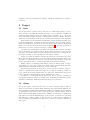
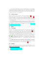
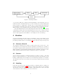
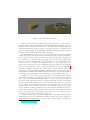
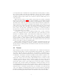
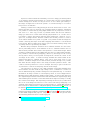
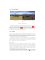
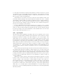
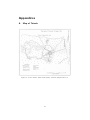
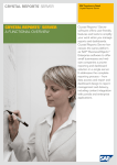
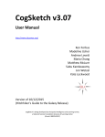
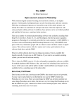
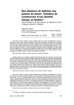
Human, Time and Landscape - Blender as a
content production tool
Juho Vepsäläinen
University of Jyväskylä
September 27, 2008
Abstract
Across time people have affected their surroundings. Relics of the past
can be seen in the current world and landscape. Understanding history helps
us to understand the present better and preserve our cultural heritage.
This project aims to produce a window to the past by using computer
generated graphics. Multiple views shall be created each going further into
the past. These views are formed as worlds in which the user can study the
village on global and local perspectives.
A small Finnish village, Toivola, was chosen as the target for this venture.
Literature mentioning Toivola exists beginning from the Middle Ages making
Toivola an ideal target.
An engine capable of rendering the world will be created. It will be based
on OpenSceneGraph, a graphics toolkit that is available under open source
license. This toolkit has been used for similar projects earlier.
Blender, a 3D production tool, and the GIMP, an image manipulation
tool, are used for content production. Both tools are based on open source.
This paper shows how these tools are used in this project. Also analysis of
the current workflow is provided.
1
Introduction
Computer graphics is a relatively young field. In 1961 Ivan Sutherland created
Sketchpad program which allowed the user to draw using a computer [1]. Since
then computer graphics have been used for various different purposes such as
games [2], movies (Tron) and of course personal computing.
As computing technology has advanced, using computer graphics in massive
scale has become more affordable. This has made it possible for scientists to
model virtual worlds describing past (Virtual Pompeii [3], Praha 4D1 ). Computer
graphics have become invaluable tool for historians wishing to understand better
what past has looked like while allowing them to share their vision with others.
In the next section the project itself is covered. Its rationale, targets, timetable
and organisation are discussed. After that the content production tools used are
taken a look at. Then we will move on discussing current content production
1 http://www.praha4d.net/index_en.html
1
workflow. It is both described and analysed. Finally we summarise the results in
conclusion.
2
2.1
Project
Goals
The project aims to produce view to the past of a small Finnish village, Toivola,
that is known for its culturally valuable landscape. Toivola represents a traditional
Tavastian village where houses are tightly grouped together. It is one of the
most westernmost villages in Hollola, a large parish southeast of Häme. Hollola is
situated in southern Finland near the city of Lahti 100 kilometers north to Helsinki.
What makes Toivola interesting is that there is literal material available even
from the Middle Ages. Furthermore maps are available since the 18th century.
Fields and meadows of Toivola are close to the village center unlike its neighboring
villages. You can see this in the map found at appendix A . This sort of formation
makes area of Toivola compact and easy to comprehend.
The time span studied spans 600 years from 15th till 20th century. This time
span is divided into ten separate worlds. Each century is planned to have at least
one world. As modern times are approached and the frequency of change in the
landscape increases, so does the amount of worlds per century.
Visitor of a world can examine it from both ”bird’s eye“ and ”worm’s eye“ view.
Bird’s eye view allows the visitor to see the world in global perspective. This helps
the visitor to understand the vastness of fields and forests and their usage. On
worm’s eye view the visitor can study individual yards and their buildings.
Engine capable of rendering worlds will be created. It will be based on OpenSceneGraph, an open source based scene graph solution. OpenSceneGraph offers
additional layer of abstraction which lies on top of OpenGL.
Besides producing views on the past of Toivola, the project aims to help scientists to understand how 3D technology can be used as a method of study. It
is not just about showing existing data in a new form. Furthermore the project
helps to preserve cultural heritage for the generations to come.
In addition to creating 3D worlds, the project aims to produce a traditional
monograph and articles based on research done. Furthermore worlds will be made
available for museums. Additionally they may find use in education.
2.2
History
The project began on 2007 and the goal is to have it ready by 2010 or 2011 at
latest. Project leader, professor Marko Lamberg, ethnologist Minna Mäkinen and
historian Merja Uotila from the Department of History and Ethnology of University
of Jyväskylä are responsible for the content production. Juhani Forsman, chief of
Agora Virtual Reality Environment Center (AVEC) of University of Jyväskylä is
responsible for technical implementation of the project. Cooperation is done with
City Museum of Lahti, experts of the field and of course current residents of
Toivola. Notably City Museum of Lahti has done archaeological work benefitting
this project.
2
The project was started after Department of History and Ethnology and AVEC
discussed about possible cooperative ventures. This particular project was chosen
because there was already an existing local project. This made it possible to use
already gathered material. Especially available cartographical material has helped
to define the project’s focus on landscape.
2.3
Similar Projects
There are similar projects in Finland. Kari Uotila’s Muuri project2 takes more
archaeological approach than this project. Another project, VirtualViipuri 3 , is
focused on buildings. Our project models slightly larger geographical area on
longer scale of time. The scope of project is larger also in sense that our project
does not focus merely on buildings but it also includes the scenery and landscape
encompassing them.
It is notable that this project studies countryside on such a timespan that has
not been earlier studied in this scale. Archaeological studies focused on countryside
of Middle Ages in Finland have emerged only recently in the beginning of the
21st century. One such a study group, MARK, can be found at http://www.
helsinki.fi/arkeologia/mark/ .
3
Tools
3.1
The GIMP
The GIMP, GNU Image Manipulation Program, is a versatile image manipulation
program, as one might infer from its name. It is available under GPL4 (GNU
General Public License) license. GPL is an open source license. Briefly put its
purpose is to ensure that code released under GPL remains under GPL if a program
based on GPL is sold commercially. This is so called viral clause of GPL.
Peter Mattis and Spencer Kimball started development of the GIMP around
1995. After years of development GIMP version 1.0 was released on June 5,
1998. [4] The GIMP’s most current version at the time is 2.4.7. It follows evenodd versioning scheme where even (2.2, 2.4, ...) versions are considered stable
and production ready while odd (2.3, 2.5, ...) version numbers signify development
version.
The GIMP is the leading image manipulation solution in the open source world
and it can be considered to be open source more or less equivalent of the leading
proprietary application, Adobe Photoshop. As an interesting curiosity effort has
been done to mimic Photoshop as projects like GIMPshop5 show.
3.2
Blender
Just like the GIMP, Blender is available under GPL license. This wasn’t the case
always however. Before year 2002 it was proprietary software. “Luckily”, depending
2 http://www.muuritutkimus.com/
3 http://www.virtuaaliviipuri.tamk.fi/
4 http://www.gnu.org/copyleft/gpl.html
5 http://www.gimpshop.com/
3
Figure 1: Modeling workflow
on your view, NaN, the company developing Blender, went bankcrupt and as a
result the leader of the Blender project, Ton Roosendaal, succeeded in making the
investors agree to a simple plan. The plan was to collect hundred thousand euros
in exchange for the rights to the source code that would be relicensed under GPL.
With the help of the community the sum was raised in seven weeks. [5]
Since then Blender has become a full-fledged 3D suite that rivals its proprietary
counterparts in many areas even surpassing them in some. It is a complete solution
offering features for whole 3D production pipeline though some tasks are better
done in other applications the GIMP as one example in case of texturing.
4
Workflow
So far the modeling work has focused on buildings. Most of the details of the
buildings are preserved in the modeling process. An important part of the detail is
provided by textures based on real images. 1 shows the basic steps of the process
4.1
Reference Material
The reference material used consists of maps, plans, photos and books. Current buildings of the village have been photographed. Sometimes it is possible to
use textures available under permissive licenses and then process them as needed.
When modeling a certain building available reference material is analysed. Sometimes separate buildings share features making it possible to reuse them.
4.2
Sketches
As the reference material is analysed sketches are drawn on paper. The main
purpose of these sketches is to catch the main proportions and features of the
building. Additionally a list of features to be modeled may be written as a checklist.
The sketches don’t have to be perfect as long as they capture the basic goals we
are after.
4.3
Modeling
Using the proportions and observations made in sketching phase a simple box
model is created in Blender 2(a). It helps at later stages if this is done carefully.
This model is used as a guideline for details. After details are in place, this part
of the model becomes redundant and can be removed.
4
(a) Progress after first stage of modeling
(b) Progress after adding details
Figure 2: Various stages of modeling
In this case the model is creating using polygonal approach. There exist alternative approaches such as NonUniform Rational B-Spline (NURBS) and Constructive Solid Geometry (CSG) based ones. These are better suited for industrial
modeling tasks which require accuracy. Polygonal approach is commonly used
due to its relative simplicity. Furthermore polygonal modeling techniques, such as
subdivision surface based modeling, make it powerful.
In polygonal approach the object to be modeled is created as a mesh. Meshes
consist of polygons, also known as faces which is the most commonly used term.
Faces consist of vertices that are connected to each other by edges. A vertice can
be considered to be a point in 3D space. Edge on the other hand is nothing more
than the connection between two vertices. In addition to those properties a face
forms a closed loop of edges and is considered solid. A loop of edges that is not
solid does not form a face. In case of Blender faces can consist of three (triangle
face) or four (quad face) vertices. Some other applications, such as Wings3D6 ,
offer the possibility to use faces that consist of five or more vertices. These sort
of faces are commonly known as NGONs. Blender offers a way to hide faces by
using FGONs. FGONs are like NGONs expect that they do not offer the flexibility
of the latter as they are still bound by limitations of the geometry they hide.
Usually it is a good idea to keep the geometry of the mesh mostly in quads.
This makes it possible to use Blender’s effective loop tools. Given some edge an
edge loop can be determined. A simple way to do this is first to pick a vertex of
the chosen edge. After this we need to pick another vertex opposite of the vertex
we did not pick. Note that this can be done only if the vertex chosen is connected
to four edges. In other words the valance of the vertex is four. If we found a
vertex opposite of the vertex we did not pick, we repeat this operation on it till we
reach a situation in which we either find a vertex we have already seen before or
we end up in a situation where opposite vertex cannot be found. After this we still
need to check the case of the initially not chosen vertex to the other direction.
As a result of this operation we have an edge loop.
So why are edge loops so powerful? Edge loops can be moved between their
neighbouring edge loops. Furthermore additional edge loops can be created between them and deleted at will of course. Creation and placement of edge loops
6 http://www.wings3d.com/
5
is an important task. Sometimes we end up with vertices having valance of three,
five or more in which case they are terminated. This is not a problem. Almost
any mesh except for the most trivial ones end up having these sort of vertices.
A skilled modeler can place these sort of vertices at places in which they do not
cause any harm.
After the basic model is ready, details of the model can be built. A detailed
model can be seen in figure 2(b). In case the building to be modeled has plank
walls, planks are modeled using array modifier provided by Blender. Array modifiers
allows the user to duplicate object based on given offset and amount of duplicates.
Array modifier has been useful for modeling other features, such as walls of a log
cabin or tile roofs, as well. At a later point in the modeling process, as the model
has gotten its shape and looks right, array modifiers are usually applied to gain
more control over the result. Sometimes it is necessary to cut the last plank in
the plank row for instance. Another case forcing into this can be seen at the ends
of a house where the roof is angled.
In addition to walls and roof the building usually needs a couple of mirrors,
some doors, chimneys and lots of other small detail. More often than not, most
windows of a building are alike. This means that actually only one needs to be
modeled. Rest can be created using linked copies of the original one. Linking
makes it easy to make changes to the models as changes made to any linked
model propagate to others. Blender offers also library linking features meaning
multiple files can share the same models. This feature hasn’t been used in the
project yet though it could be potentially useful.
When possible, existing models are used for details. Sometimes they may need
some tiny tweaks to geometry or textures. Usually it is worth the effort though.
As the amount of existing models and textures increases, the work becomes progressively easier.
4.4
Textures
When details are in place it is time to texture them. UV coordinates for details are
formed by adding seams to them and unwrapping them carefully. UV coordinates
are used to map 2D data onto 3D surfaces. UV texturing is a standard way to
achieve this. After a suitable unwrap has been created, it is exported as an image
from Blender. This image is loaded in the GIMP and the texture is painted on it.
A good way to visualize what 2D to 3D mapping means is to construct a cube
using paper, scissors and some folding. After thinking about it a while you may
come into conclusion that in order to construct a cube, you need to cut it out in
a certain way for it to fold into a cube. In case of Blender you do this operation in
inverse way. First you have a cube. After this you add some seams to it just like
the edges of the cut paper. When you tell Blender to unwrap the mesh, you get a
nice 2D presentation of it. Of course one simple way to construct a cube is to cut
out individual faces and then use some glue to connect them. You can unwrap a
mesh this way too. However in practice this sort of unwrap is not useful in most
cases. The challenge of unwrapping lies in where to put the seams. In general this
problem is partially solved by placing seams into places where they naturally are.
In other words using places where texture incontinuities can be seen are ideal.
6
In practice I have found that sometimes you need to design your unwrap based
on an existing, already painted texture. It could be that you have a great window
texture already done. In this case all you need to do is to match your unwrap to
the image. It might not be the most “purest” or conventional way to do it but it
has proved to be effective.
Painting a texture isn’t really painting in the most literal sense of word. The
main goal in this case is to get most out of existing reference material. Sometimes
it is possible to achieve this by using slight tweaks such as perspective correction
and clone tool. Let’s say you have a potential texture but the best reference
image you have has not been taken directly perpendicular to it. In this case it
is possible to extract the texture and then apply perspective correction on it to
get a nice, rectangle texture. Another common case is that you have to create a
wood texture suitable for a plank or log wall. The problem is that the image has
“seams” caused by the shape of the wall. Mapping this texture to a model would
not be trivial. Hence it makes more sense to get rid of these seams by using clone
or perhaps heal tool provided by the GIMP.
Besides using techniques described above seamless textures are used often.
This is particularly true for such materials as wood. Seamless textures are not
without their problems and it takes some expertise to create them though. When
creating a seamless texture in the GIMP the basic idea is to make seams paintable.
It is possible to achieve this by wrapping (offset tool) the image in both x and y
axes by half so that you end up with an image that contains all corners of the
old image at the center. To make an image seamless the seams visible at the
seamed area must be carefully edited. This can be done using clone tool for
instance. Seamless images are not without their problems though. It is possible
that when tiled the images have some clearly noticeable pattern in them. This
could be caused by variation in color for example. One way to get rid of this sort
of problem is to remove low frequency data from the image.
The easy way to do this is to use a high pass filter. Doing this manually gives
more influence over the result though. Image can be considered to consist of a
sum of different frequency domains arranged in some particular way. To see what
information an image contains on low frequency levels, it can be simply blurred.
Blurring removes high frequency detail from the image. To remove this data from
the original image it must be inverted and then mixed with the original image using
desired mixing mode and factor. Note that after this it may be necessary to modify
the contrast of the image. Also depending on mixing mode used, it is possible that
the colors of the image are removed. Colors can be restored by remapping color
channels of the image (red, green, blue) by using levels tool. Jeremy Birn describes
this technique in detail in his book Digital Lighting and Rendering [6] and also on
his website http://www.3drender.com/light/EqTutorial/tiling.htm.
In addition to techniques described above it is possible to generate seamless
textures using image synthesis. Resynthesizer7 and Texturize8 are plugins available
for the GIMP designed this purpose. They haven’t found much use yet but offer
an interesting alternative that is worth trying out.
7 http://www.logarithmic.net/pfh/resynthesizer
8 http://gimp-texturize.sourceforge.net/
7
4.5
Textured Model
(a) Textured model
(b) Textured model with other buildings of
the yard
Figure 3: Textured models
After the model has been textured, it is probably a good idea to render it. Of
course this is done multiple times during the texturing process itself. 3(a) shows
a render of a textured model. In 3(b) the model can be seen on the yard with
other buildings. Current trees use temporarily simple billboard based solution. Also
the scenery is work in progress. The images have been rendered using Blender’s
internal renderer using an angular map for the sky.
4.6
Analysis
The use of open source tools makes it possible to alter those tools should it be
necessary. If the modifications can be done using scripts or plugins, the development can be easily maintained and shared with others. More invasive, source code
altering modifications, incur additional maintenance cost as the code needs to be
in sync should new versions of the program be released.
As Blender is the main tool used in the workflow, I will focus on explaining how
current workflow could possible be done more efficient. I know many things may
change for better as the new, long awaited version, 2.50 comes out. It doesn’t
hurt to outline issues with the version used though.
4.6.1
Tools
Blender offers a wide range of features for a wide range of users. The fact is
however that in this case most of the tools are unused. A rough estimate might
be that the workflow utilizes 20 percent of available tools at best. The real figure
may be a lot lower though as there is no valid way, except for subjective one,
available to help evaluating this. What this means is that the redundant tools are
actually hindering work. How can this be possible?
According to Fitts’ law, user interface elements with selector (ie. menus, lists
and like) with reasonable amount of options are faster to use [7]. There are other
interesting results available as well but let’s concentrate on this. If it was possible
8
to customize user interface in manner that makes it possible for the user to get rid
of redundant tools, it would make him more productive. This would also decrease
amount of cognitive load making it easier to adapt the user interface into a form
that is easier to learn and understand.
Customization is not much of use for a new user of the software. In this case
reasonable default settings and the first impression matter the most. Powerful
customization features make it possible for advanced users to adapt software to
their own purposes. This would mean demarcation from the commonly accepted
and used notion that software is given to the user “as-is”. Notable exceptions to
the rule, such as Eclipse, exist however.
In case of Blender this would mean abstraction of current tools to a higher
level. Furthermore tools could consist of node trees describing how a certain tool
works. In other words the distinction between the user and the developer would
become more hazy as the users themselves could assemble their tools for some
specific task should they want to do so.
4.6.2
Layer System
Another shortcoming of Blender especially in this sort of workflow can be considered to be its layer system. Blender’s layer system has a fixed amount of layers
limiting the amount to twenty. An object belongs to one or more layers. The
visible layers can be controlled in the user interface using approach where each
layer is shown as a tiny button that is toggled or not depending on its state. What
is problematic in this approach however that it makes it an effort to remember
which layers are meant for which purpose. Sure it’s possible to set up some predefined system where you put your objects on layers 1-5, lamps on 6-10, cameras
on 11 and so on... This isn’t quite practical however as the relationship is not
explicitly defined, unless you write it somewhere, such as a document in Blender’s
text editor.
One possible layer system approach that would fit this workflow would be to
use implicit layers with the possibility to define explicit ones. In other words each
created object would exist on a layer of its own. As the amount of objects changes,
the amount of layers available changes dynamically. This guarantees that no layer
is empty and without purpose. Explicitly defined layers are used to group objects.
In other words an explicit layer would be a close equivalent to current concept of
a group in Blender.
There are a couple of issues in this approach that must be taken into account
however. First of all as the amount of objects in the scene increases, so does the
amount of layers. This could lead to a huge number of layers. One solution to
this problem would be to offer different views on layers. One way to do this would
be to make it possible to create metalayers which contain certain layers defined
by given rule. Possible rules could include object type, object name (partial match
even) and so on. Several ways to extend metalayer as a concept exist (boolean
rules and so on) but something simple like just mentioned could help significantly
with the problem.
9
4.6.3
Other Issues
Array modifier is a great tool as long as you can use it. The primary handicap
of the array modifier is that you cannot use a boolean modifier after it to cut
the geometry. Hence you have to give up the greatest benefit, non-destructive
approach to modeling, as you have apply it and cut it manually. If it was possible to
use the boolean modifier this way, it would make it possible to use more procedural
approach in modeling making it easier to make changes to the models later with
ease.
Another tiny, yet irritating issue is the way images are applied on UV textures
of materials. This is probably due to the way the system has been designed but
nevertheless it takes many steps to do this. Normal workflow currently can be
something along this:
1. Unwrap mesh.
2. Open an image to unwrap in UV/Image editor.
3. Add a texture to material of the object containing the mesh.
4. Set texture as an image, set the image it and set filter to low value (0.1).
High filter values, such as default 1.0, tend to produce blurry results on OSA
(anti-aliased) renders so it’s better to change it to be a bit lower. This is
personal preference though.
So as you can see that’s quite a many steps. And sometimes this needs to be
done many times for many objects which isn’t quite fun on the long run.
When creating renders, it’s usual that the render settings have to be tweaked
a bit before each render. Blender does not have an easy way to set up render
templates that can be reused as needed. Should it have templates it would make
handling renders an easier task.
5
Conclusion
So far the project has been more about establishing a simple workflow that works.
In the future more effort will be spent on optimising it further. This article presented a way in which Blender can function as a part of such. Furthermore aspects
that might help to optimize workflow were identified.
10
References
[1] Ivan Edward Sutherland. Sketchpad: A man-machine graphical communication system. Technical Report UCAM-CL-TR-574, University of Cambridge, September 2003. URL http://www.cl.cam.ac.uk/techreports/
UCAM-CL-TR-574.pdf.
[2] J. Martin Graetz. The origin of spacewar. Creative Computing, 1981. URL
www.gillesboulet.ca/textes/spacewar.pdf.
[3] Jeffrey Jacobson and Jane Vadnal. The virtual pompeii project. In Proceedings
of World Conference on E-Learning in Corporate, Government, Healthcare,
and Higher Education, 2005.
[4] Gnu image manipulation program - user manual. URL http://docs.gimp.
org/en/.
[5] Ton Roosendaal. The Official Blender 2.3 Guide. No Starch, City, 2004. ISBN
9781593270414. URL http://www.blender.org/documentation/htmlI/.
[6] Jeremy Birn. [Digital Lighting] and Rendering. New Riders, Indianapolis, 2006.
ISBN 0321316312.
[7] Paul M. Fitts and Michael I. Posner. Human performance. Basic concepts in
psychology series. Greenwood, Westport, Conn, 1979. Paul M. Fitts; Michael
I. Posner.
11
Appendices
A
Map of Toivola
Figure 4: Source: Kuusi, Sakari 1980 (1935). Hollolan pitäjän historia 1.
12