1
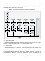
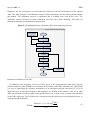
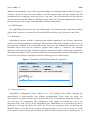
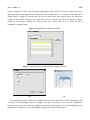
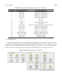
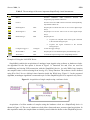
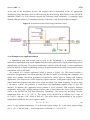
Sensors 2014, 14 9762 SimpleDAQ is developed as a USB human interface device (HID). The USB HID class is a part of the USB specification for computer peripherals: it specifies a device class for human interface devices such as keyboards, mice, game controllers, and other devices [25]. Most of operating systems natively support the USB HID class, therefore the end-users do not need to install additional drivers. The maximum transfer rate for USB HID devices is limited to 64 kB/s. SimpleDAQ firmware is developed in the form of a simple server application i.e., the firmware periodically checks for incoming requests (messages) from USB (Figure 3). An application on the PC (client) needs to initiate a communication session with the SimpleDAQ and sends a request(s). When the SimpleDAQ receives an incoming request, it performs the requested task(s) and transmits the results back to the client application (Figure 3). Requests and responses are in the form of byte messages (packets). An example of a request/response message is presented in Table 3. Table 3. An example of a request/response message (acquire waveform from analogue input). Message Type Request message Response message Byte Number 0 1 2 3 4 5 6 7 8 9 0 1 to (2 Number of samples ) Byte Meaning Command (CMD_READ_ANALOG_WFM) Sampling channel (pin number) Reference (0: internal, 1: external) Trigger (0: disable, 1: enable) Sampling frequency (1. byte) Sampling frequency (2. byte) Number of samples (1. byte) Number of samples (2. byte) Trigger timeout in ms (1. byte) Trigger timeout in ms (2. byte) Command (CMD_READ_ANALOG_WFM) Acquired data The maximum message size for the USB HID class is 64 bytes. All the request messages are smaller than 64 bytes, whilst the response messages can be larger. In this case the firmware splits the response message into several 64 bytes messages. The current version of SimpleDAQ firmware supports the following requests from the client: (1) read the state of one or more digital inputs, (2) set/reset one or more digital outputs, (3) acquire single value from one or more analogue inputs, (4) acquire waveform from analogue input, (5) configure the trigger parameters, (6) send (forward) the retrieved data to SPI bus, (7) configure the PWM frequency on PWM output, (8) configure the duty cycle on PWM output (9) reset SimpleDAQ and (10) configure SimpleDAQ pins according to the input configuration data. The flowchart of the request message processing procedure is presented in Figure 4. More than half of the SimpleDAQ pins are flexible which means that the functionalities of these pins can be changed without microcontroller reprogramming. For example, an individual pin can be configured as digital input, digital output, analogue input, PWM output or one of three SPI lines. The pin configuration is achieved using the SimpleDAQ configuration utility (as described in the next section). This utility creates the configuration data and stores it within the microcontroller flash