1
Application Report
SPRAAX5 – August 2008
Software Migration From TMS320DM642 to
TMS320DM648/DM6437
Joseph Coombs and Tim Harron .........................................................................................................
ABSTRACT
This application report describes the differences in software development tools
between DM642 and the newer DSP-only devices in the DaVinci™ platform such as
DM648 or DM6437. In particular, the old and new methods of driving and accessing
peripheral devices are compared between devices. Examples with partial source code
are presented for the primary means of peripheral access: DM642 functional chip
support library (CSL), DM648/DM6437 register CSL, and DM648/DM6437 platform
support package (PSP) drivers. Philosophical differences between these methods, as
well as recommended migration paths between them, are discussed in depth.
This document briefly describes the use of the enhanced direct memory access
(EDMA) low-level driver for the DM648 and DM6437. For more information on EDMA
usage, see How to Use the EDMA3 Driver on a TMS320C643x Device (SPRAAN4),
which includes detailed examples with full source code.
This document does not describe hardware differences between devices. That topic is
already covered in existing application reports.
Project collateral and source code discussed in this application report can be
downloaded from the following URL: http://www-s.ti.com/sc/techlit/spraax5.zip.
Contents
1
Introduction .......................................................................................... 1
2
Using Functional CSL on DM642................................................................. 6
3
Using PSP Drivers on DM648/DM6437 ......................................................... 8
4
References ......................................................................................... 13
Appendix A
PSP Overview ........................................................................... 14
List of Figures
1
2
3
A-1
1
Peripheral Access Software Layers for DM642 Compared to DM648 or DM6437 ........ 2
EDMA3 LLD Dependencies ....................................................................... 6
Adding a Device to TCF Using the Graphical Editor ........................................... 9
Structure of a PSP Driver ........................................................................ 14
Introduction
This application report describes software application migration from DM642 to DM648 or DM6437.
Hardware differences, such as changes between C64™ and C64+™ DSP, are not discussed. Instead, the
changes are explored in software development tools, specifically tools used to access peripheral devices
and EDMA. You should be able to translate old programs to a newer device, identifying disconnects and
critical differences between old and new tools and migrating functionality as seamlessly as possible.
DaVinci, C64, Code Composer Studio, DSP/BIOS are trademarks of Texas Instruments.
All other trademarks are the property of their respective owners.
SPRAAX5 – August 2008
Submit Documentation Feedback
Software Migration From TMS320DM642 to TMS320DM648/DM6437
1
Introduction
www.ti.com
While the DM648 is the proper successor to the DM642, the DM6437 is also considered a viable migration
target. Both the DM648 and DM6437 are single-core, DSP-only devices, which differ primarily in hardware
considerations: clock speed, peripherals included, etc. Their development tools, digital video software
development kits (DVSDKs), are very similar; therefore, they are comparable targets for software
migration.
1.1
Prerequisites
This document is written using the following software versions. Please use these or subsequent releases if
attempting to follow the example procedures or source code.
• Code Composer Studio™ software 3.3
• DSP/BIOS™ software kernel foundation 5.31.08
• DM642 FCSL 2.31.00.16
• DM648 PSP 1.10.00.09
• DM648 EDMA3 LLD 1.03.01.01
• DM6437 PSP 1.00.02.00
• DM648 DVSDK 1.10.xx.xx
• DM6437 DVSDK 1.11.xx.xx
1.2
Peripheral Access
This section covers changes regarding the initialization and use of peripheral devices. For both old and
new devices, low- and high-level methods for accessing peripherals are described. Additionally, suggested
migration paths for the existing DM642 applications are given.
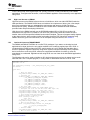
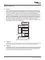
Figure 1 shows the layers of peripheral access across old and new devices. Figure 1 is intended to give a
broad overview of the different methods and how they relate to each other.
DM642
High-Level
Application
DM6437, DM648
High-Level Application
PSP - DDA Layer
DDK/User
Abstraction
Low-Level
Application
FCSL
PSP - DDC Layer
PSP - LLC Layer
RCSL
Low-Level
Application
RCSL
Figure 1. Peripheral Access Software Layers for DM642 Compared to DM648 or DM6437
1.2.1
Low-Level Access on DM642
For DM642 applications, low-level peripheral access refers to using a peripheral device through the
functional chip support library (FCSL). The FCSL packages provide application programming interfaces
(APIs) to initialize and control peripheral devices with relatively little abstraction. Rather than making one
function call to complete an input/output (I/O) transaction, it may be necessary to make separate calls to
initiate, manage, and terminate a single transfer. The use of FCSL does not require DSP/BIOS. For more
information and example code using FCSL with the DM642, see Section 2.
2
Software Migration From TMS320DM642 to TMS320DM648/DM6437
SPRAAX5 – August 2008
Submit Documentation Feedback
Introduction
www.ti.com
FCSL is built on top of the register-layer CSL (RCSL), but RCSL is rarely used directly in the DM642
applications. Throughout this document, a low-level DM642 application refers exclusively to an application
using FCSL.
1.2.2
High-Level Access on DM642
High-level access on the DM642 refers to the use of minidrivers, which run within DSP/BIOS under the
IOM specification. The DM642 DVSDK does not include a full complement of drivers, but a few sample
drivers are provided to help you understand the requirements and structure of IOM. The driver
development kit (DDK), available for DM642 but not included with the standard DVSDK installation,
provides further help for developing IOM drivers.
IOM drivers for the DM642 typically use the DSP/BIOS-standard GIO or SIO APIs to perform I/O
transactions at a high level. For instance, one call to GIO_submit may initiate and control an entire
transfer, then call a user-specified callback function when complete. This sort of program readily migrates
to the newer devices, which provides similar functionality through a PSP. No specific examples using
DM642 drivers are given in this document, but for examples using the GIO API, see Section 3.
1.2.3
Low-Level Access on DM648/DM6437
The DM648 and DM6437 DVSDKs do not offer FCSL packages. If you want to to develop low-level
applications for these devices, the only option available is the underlying register-layer CSL. RCSL is
included with the DVSDK as part of the PSP, and it consists of a set of header files that allow direct
access to peripheral registers. Effectively using RCSL requires extensive knowledge of the peripheral
device, and source code using RCSL tends to be complicated and difficult for others (or even the
programmer) to understand. Applications built using RCSL are even lower level than DM642 applications
using FCSL.
The following code can be used to initialize an I2C device and process one byte in master receive mode.
Note that this is not a complete program; it is only meant to demonstrate the form of RCSL code.
#include <cslr_i2c.h>
#include <soc.h>
CSL_I2cRegsOvly i2c0Regs = (CSL_I2cRegsOvly)CSL_I2C_0_REGS;
int buffer;
void main()
{
// Reset I2C device
CSL_FINST(i2c0Regs->ICMDR, I2C_ICMDR_IRS, RESET);
// Configure I2C
i2c0Regs->ICMDR = CSL_FMKT(I2C_ICMDR_MST, MASTER)
| CSL_FMKT(I2C_ICMDR_TRX, RX_MODE)
| CSL_FMKT(I2C_ICMDR_RM, DISABLE)
| CSL_FMKT(I2C_ICMDR_DLB, DISABLE)
| CSL_FMKT(I2C_ICMDR_FDF, DISABLE)
| CSL_FMKT(I2C_ICMDR_XA, 7BIT)
| CSL_FMKT(I2C_ICMDR_BC, 8BIT);
// Set slave addr
CSL_FINS(i2c0Regs->ICSAR, I2C_ICSAR_SADDR, 0x50);
// Configure I2C clock for 200 kHz (from 27MHz input clk)
CSL_FINS(i2c0Regs->ICPSC, I2C_ICPSC_IPSC, 0x02);
CSL_FINS(i2c0Regs->ICCLKL, I2C_ICCLKL_ICCL, 0x12);
CSL_FINS(i2c0Regs->ICCLKH, I2C_ICCLKH_ICCH, 0x12);
// Clear ICSTR (read and write back)
i2c0Regs->ICSTR = i2c0Regs->ICSTR;
while (i2c0Regs->ICIVR != 0)
asm(" nop");
// Take I2C out of reset
CSL_FINST(i2c0Regs->ICMDR, I2C_ICMDR_IRS, ENABLE);
// Wait for bus busy to clear
while (CSL_FEXT(i2c0Regs->ICSTR, I2C_ICSTR_BB)
== CSL_I2C_ICSTR_BB_BUSY)
asm(" nop");
// Generate START
CSL_FINST(i2c0Regs->ICMDR, I2C_ICMDR_STT, SET);
// Wait for data received
SPRAAX5 – August 2008
Submit Documentation Feedback
Software Migration From TMS320DM642 to TMS320DM648/DM6437
3
Introduction
www.ti.com
while (CSL_FEXT(i2c0Regs->ICSTR, I2C_ICSTR_ICRRDY)
== CSL_I2C_ICSTR_ICRRDY_FALSE)
asm(" nop");
buffer = (int)(i2c0Regs->ICDRR);
// Generate STOP
CSL_FINST(i2c0Regs->ICMDR, I2C_ICMDR_STP, SET);
}
1.2.4
High-Level Access on DM648/DM6437
Unlike the DM642, the DM648 and DM6437 DVSDKs each include a full complement of IOM-compliant
drivers with the default installation. These drivers comprise a PSP, which services each and every
peripheral device. PSP drivers, like other IOM drivers, allow high-level peripheral access via the GIO or
SIO APIs. For more information and example code using PSP drivers, see Section 3. High-level peripheral
access on the DM648 or DM6437 refers to the use of the PSP drivers.
The PSP includes full source code for each driver, allowing you to modify and rebuild drivers if necessary.
The PSP source code is modular and code is separated into different layers according to function. For
more information on the organization of a PSP driver, see Appendix A.
1.3
Migrating High-Level DM642 Applications
Migrating high-level DM642 applications to the new DVSDK is straightforward. If the existing code uses
IOM-compliant drivers, it should be built using the GIO or SIO APIs. Converting this code to use a
PSP-delivered IOM driver is straightforward: determine what changes, if any, are required among the
parameters passed in your existing GIO or SIO calls. Also, to determine how the driver is initialized and
controlled at run time, see the DM6437/C6424 DSP/BIOS PSP User’s Manual and sample application
included with the DVSDK installation for the DM6437/6438 devices. Typically, the device is initialized with
a parameter struct that must be provided in your application source code.
There are a few caveats to consider, however. First, DM648 and DM6437 applications using DSP/BIOS
5.x are configured using textual configuration files (TCFs). Older DM642 applications using DPS/BIOS
4.90 may be configured using a configurable database (CDB) file, which is vastly different from TCF. Code
Composer Studio 3.3 can automatically migrate older DM642 projects to DSP/BIOS 5.x, which can spare
you the effort of creating a TCF file from scratch. A comprehensive description of TCF falls outside the
scope of this application report, but a description of TCF contents necessary to initialize a peripheral
device for use by a PSP driver can be found in Section 3.
Another potential problem is a mismatch in functionality between a DM642 driver and the new device's
PSP driver. For instance, the older driver may use the SIO API, while its replacement uses only GIO. A
more severe situation could be that the PSP driver does not support a certain mode of operation that was
serviced by the older driver. These problems must be addressed on a case-by-case basis, and at worst
may require that you modify the PSP driver to suit your needs.
Finally, it is possible that the DM642 application uses a non-IOM-compliant driver; it may even use a
non-standard API. In this case, the existing code needs to be translated to the GIO or SIO API. For a brief
description of how to use these APIs, see Section 3.
1.3.1
Summary: Migrating High-Level DM642 Applications
1. Setup TCF/TCI to initialize peripheral device for the PSP driver.
2. Verify that the existing DM642 application uses GIO or SIO API.
a. Individual PSP drivers may support GIO, SIO, or both. Check that the desired API is supported by
the driver.
b. If the existing application does not use GIO or SIO, translate the existing driver calls to one of these
APIs.
3. Verify that the mode of operation (i.e., operating parameters) is supported by the PSP driver.
4. Modify the existing GIO, SIO calls to use parameters expected by the PSP driver. See the
DM6437/C6424 DSP/BIOS PSP User’s Manual and sample application included with the DVSDK
installation for the DM6437/6438 devices.
4
Software Migration From TMS320DM642 to TMS320DM648/DM6437
SPRAAX5 – August 2008
Submit Documentation Feedback
Introduction
www.ti.com
1.4
Migrating Low-Level DM642 Applications
Due to the absence of FCSL in newer DVSDKs, there is no clean migration path for low-level DM642
applications. Because of this, the existing application must be rewritten in one of two ways: using RCSL or
using PSP. Which path to follow is a decision that must be made by you. The two options are summarized
in the following sections.
1.4.1
Rewrite Using RCSL
The application is rewritten at a lower level. The resulting source code will likely be denser and less
readable, but fine control over the peripheral is maintained, or even enhanced. RCSL allows the peripheral
to be exercised in any way supported by its documentation, but its use requires that you be an expert in
the use of that peripheral.
1.4.2
Rewrite Using PSP
Direct control of the peripheral is surrendered to the PSP driver. This allows the program to operate at a
higher level, but it may not be an acceptable tradeoff if the desired functionality is not supported by the
PSP driver. For many applications, this should not be a problem. The PSP driver for each peripheral is
intended to service all modes of operation possible on the EVM hardware. If the PSP driver does not
support an application, it can be modified. For more information on the structure of a PSP driver and tips
on where to look for functionality that you may want to change, see Appendix A. For general information
on how to initialize and use a PSP driver, see Section 3.
1.5
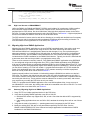
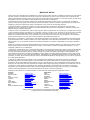
Using the EDMA3 LLD on DM648/DM6437
The DM648 and DM6437 offer EDMA control through the EDMA3 low-level driver (LLD), which is included
with the DVSDK installation. The EDMA3 LLD may be packaged either as part of the PSP or as a discrete
package. The EDMA3 LLD consists of three libraries: the EDMA3 driver library (EDMA3 DRV) provides a
FCSL-like API to control EDMA transactions; EDMA3 resource manager library (EDMA3 RM) tracks
device resources and services EDMA3 DRV; and a final library provides a convenient initialization routine
and abstracts the other two libraries from the DSP/BIOS operating system. You can replace the final
library, but a standard implementation is included with the EDMA3 LLD installation. This sample library is
suitable for all DSP/BIOS applications. If you want to use the driver apart from DSP/BIOS, you need to
replace the sample library.
The first step in updating an EDMA-using DM642 application is to rewrite its FCSL-based EDMA2 control
using the newer, EDMA3 DRV API. Since this API operates on a level of abstraction similar to FCSL, the
process should be straightforward. For more information regarding initialization and use of the EDMA3
LLD, see the EDMA3 Driver (DRV) User's Guide and the EDMA3 Resource Manager (RM) User's Guide
included with the EDMA3 LLD installation. Also, see How to Use the EDMA3 Driver on a TMS320C643x
Device (SPRAAN4). Newer releases of the EDMA3 LLD are packaged using RTSC, which is not
discussed in the above application note.
The second step is to revise existing EDMA calls to accommodate changes between EDMA versions and
to take advantage of new features in EDMA3. For more information, see the EDMA v2.0 to EDMA v3.0
(EDMA3) Migration Guide (SPRAAP4).
SPRAAX5 – August 2008
Submit Documentation Feedback
Software Migration From TMS320DM642 to TMS320DM648/DM6437
5
Using Functional CSL on DM642
www.ti.com
EDMA-Using Application
EDMA3
DRV
DSP/BIOS
EDMA3
“Sample”
Library
EDMA3
RM
EDMA3 Device Hardware
Figure 2. EDMA3 LLD Dependencies
2
Using Functional CSL on DM642
The FCSL is a commonly used tool for many of the older TI DSP devices (pre-C64x+ with the exception of
C6455). The CSL was developed to give you easier control and access to a device's peripheral registers.
Instead of bit-banging registers through a pointer, the CSL provides several APIs allowing peripheral
control at a higher level. The FCSL is essentially replaced in newer C64x+ DSP-only devices (such as
DM6437 and DM648) by the PSP drivers, which operate one level higher than the FCSL. The FCSL
provides functions to perform simple atomic operations, while a PSP driver essentially collects many FCSL
calls into a single function call that performs an entire operational task.
2.1
2.1.1
Initializing a Peripheral
Open a Handle
The first step when using the functional CSL is to open a device handle. This handle represents the
hardware in software. When calling any of the CSL API functions, the specified handle informs the
function of which specific peripheral to control. To open a handle for an I2C port, add the following to their
source file:
I2C_Handle hI2CA;
hI2CA=I2C_open(I2C_DEV0, I2C_OPEN_RESET);
The hI2CA handle is now associated with the I2C port 0. Alternatively, use parameter I2C_DEV1 to create
a handle for I2C port 1. Each handle is assigned to only one instance of one peripheral, so multiple
handles are required to control multiple peripherals.
2.1.2
Configuring the Peripheral
Once the I2C handle is opened it can be used by the other CSL functions to manipulate the peripheral's
registers. The first step is to configure the baseline/starting register values. This is done by either
populating a configuration structure, which contains all of a peripheral's registers or by passing individual
arguments for each register. The configuration structure/arguments is then passed to a PER_config()
function where PER is the peripheral module name (e.g., I2C_config or I2C_configArgs). This
configuration function takes all of the values stored in the structure and applies them to the individual
registers for the peripheral defined by the device handle.
6
Software Migration From TMS320DM642 to TMS320DM648/DM6437
SPRAAX5 – August 2008
Submit Documentation Feedback
Using Functional CSL on DM642
www.ti.com
unsigned int i2coar,i2cimr,i2cclkl,i2cclkh,i2ccnt, i2csar, i2cmdr, i2cpsc;
i2coar = I2C_I2COAR_RMK(I2C0_MASTER_ADDRESS);
i2csar = I2C_I2CSAR_RMK(I2C0_SLAVE_ADDRESS);
i2cimr = I2C_I2CIMR_RMK(I2C_I2CIMR_ICXRDY_MSK,
I2C_I2CIMR_ICRRDY_MSK,
I2C_I2CIMR_ARDY_MSK,
I2C_I2CIMR_NACK_MSK,
I2C_I2CIMR_AL_MSK );
i2cpsc = I2C_I2CPSC_RMK(I2C_PRESCALER_VALUE);
i2cclkl =
I2C_I2CCLKL_RMK(I2C_I2CCLKL_ICCL_OF(I2C_ICCLKL_REG_VALUE));
i2cclkh =
I2C_I2CCLKH_RMK(I2C_I2CCLKH_ICCH_OF(I2C_ICCLKH_REG_VALUE));
i2ccnt = I2C_I2CCNT_RMK(1);
i2cmdr = i2cmdr = I2C_I2CMDR_RMK(I2C_I2CMDR_NACKMOD_DEFAULT,
I2C_I2CMDR_FREE_BSTOP,
I2C_I2CMDR_STT_NONE,
I2C_I2CMDR_STP_NONE,
I2C_I2CMDR_MST_MASTER,
I2C_I2CMDR_TRX_XMT,
I2C_I2CMDR_XA_7BIT,
I2C_I2CMDR_RM_NONE,
I2C_I2CMDR_DLB_NONE,
I2C_I2CMDR_IRS_NRST,
I2C_I2CMDR_STB_NONE,
I2C_I2CMDR_FDF_NONE,
I2C_I2CMDR_BC_DEFAULT );
I2C_configArgs(hI2CA, i2coar, i2cimr, i2cclkl, i2cclkh, i2ccnt,
i2csar, i2cmdr, i2cpsc);
2.1.3
Other Configuration Steps
The Peripheral-Specific User's Guides, included with the driver installation, typically include a section on
how to properly initialize the peripheral. Consult these documents when writing the CSL-based
configuration code to ensure that the appropriate steps are taken for proper functionality. Assuming the
steps are properly followed, the peripheral should at this point be fully configured and ready to run.
2.2
Accessing a Peripheral at Runtime
Once a peripheral is running, you can access it through a variety of methods.
The EDMA engine is commonly used to offload the servicing of a peripheral's I/O registers away from the
CPU. Without EDMA, the CPU is forced to repeatedly break away from its current processing task to keep
the data flowing. The EDMA can assume this responsibility and allow data to be captured or transmitted
without any interruption to the CPU. Once the EDMA has captured or emptied a complete buffer to/from
the peripheral, it then informs the CPU via an interrupt.
The CSL also offers a number of functions allowing the CPU to directly interface the peripheral's I/O. This
is a less efficient than using the EDMA engine, but it can help in the early stages of coding for and testing
a peripheral. For example, the I2C requires a single 'dummy' write before it automatically begins
transferring and receiving data. There are also numerous functions which help enable fast, efficient polling
code when interrupts are not desired.
SPRAAX5 – August 2008
Submit Documentation Feedback
Software Migration From TMS320DM642 to TMS320DM648/DM6437
7
Using PSP Drivers on DM648/DM6437
www.ti.com
/* Wait BB (Bus Busy) to clear */
wait_for_bus_busy(hI2CA);
/* Invoke the start condition */
I2C_start(hI2CA);
/* Wait until Transmit Ready bit is set */
while (I2C_xrdy(hI2CA));
/* Write the data into Data Transmit register */
I2C_writeByte(hI2CA, value);
/*Generate Stop condition */
I2C_sendStop(hI2CA);
If the peripheral is no longer needed the module handle can then be closed to free up the resource.
/*Close Handle*/
I2C_close(hI2CA);
3
Using PSP Drivers on DM648/DM6437
This section details the steps necessary to initialize and use a PSP driver on the DM648 or DM6437. The
PSP is included with a standard DVSDK installation, and it allows high-level operation of peripheral
devices using the standard DSP/BIOS GIO or SIO APIs. The PSP for each device provides a full set of
IOM-compliant minidrivers for this purpose.
3.1
Initializing a Peripheral
The heart of each PSP driver is an IOM-compliant minidriver. IOM requires that the peripheral device be
declared and initialized in the project's textual configuration file (TCF). The following code initializes an I2C
device on the DM6437.
bios.UDEV.create("I2C0");
bios.UDEV.instance("I2C0").fxnTableType = "IOM_Fxns";
bios.UDEV.instance("I2C0").initFxn = prog.extern("I2C_INIT");
bios.UDEV.instance("I2C0").params = prog.extern("I2C_devParams");
bios.UDEV.instance("I2C0").fxnTable = prog.extern("I2CMD_FXNS");
Place the above code in a file with a textual configuration include (TCI) extension, such as i2c0.tci. Then
add the following line to your project's main TCF:
utils.importFile("i2c0.tci");
The TCI contents may also be placed directly in the TCF, but using TCI files allows many projects to share
a single configuration.
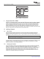
Alternatively, the TCF graphical configuration tool in Code Composer Studio can be used to automatically
generate the above lines in the project’s TCF file. Simply insert a new User-Defined Device in the
Input/Output category. This does not neatly encapsulate each device in a reusable TCI file, but allows you
to perform all configuration in the Code Composer Studio graphical user interface (GUI). Note that, in the
GUI, references to C objects must be prefixed with the underscore symbol “_” to avoid errors.
8
Software Migration From TMS320DM642 to TMS320DM648/DM6437
SPRAAX5 – August 2008
Submit Documentation Feedback
Using PSP Drivers on DM648/DM6437
www.ti.com
Figure 3. Adding a Device to TCF Using the Graphical Editor
The parameters set in the TCI in Figure 3 are, in order, the function table type, initialization function,
device parameters data structure, and the function table. If the DSP had more than one I2C peripheral, the
TCF would also require a device ID parameter to choose which would be serviced by the PSP driver.
Some of the parameters may be included in the driver library (above: fxnTable), while others are furnished
in your own source code (above: initFxn, params). The specifics vary with individual drivers; to determine
the appropriate TCF entries, see a driver's sample application and user's guide included with the driver
installation. If you are new to DSP/BIOS 5 or TCF, these sample TCF files may also help with general
system setup: memory segment usage, TSK scheduling, interrupt routines, ECM, and more.
3.1.1
•
•
•
•
•
3.2
Summary: Initializing a Peripheral
Declare and initialize the peripheral device in the project's TCF
Device parameters include the function tables in the driver library
Device parameters select between peripheral instances, if necessary (i.e., UART0, UART1)
Device parameters may reference functions or structs furnished in your C source code
For details, see the individual driver's sample application and user's guide included with the driver
installation
Linking the Driver Library
Some PSP deliverables (specifically, releases with version 1.10.xx.xx) are packaged according to the
RTSC package standard, others (version 1.00.xx.xx) are not. This section describes how to integrate
either flavor of PSP driver into a project. The process of linking a PSP driver library into an application
differs widely between these two configurations.
3.2.1
Linking PSP 1.10.xx.xx Drivers With XDCTOOLS
Newer PSP releases are packaged as RTSC packages to speed integration. To add a driver library to
your project, add a single line to the XDC configuration script (*.cfg):
xdc.loadPackage('ti.sdo.pspdrivers.drivers.i2c');
SPRAAX5 – August 2008
Submit Documentation Feedback
Software Migration From TMS320DM642 to TMS320DM648/DM6437
9
Using PSP Drivers on DM648/DM6437
www.ti.com
Individual drivers may also require additional inclusions: PAL libraries, the EDMA3 LLD, etc. Check the
driver’s sample application and see which packages are included in its XDC configuration script. If your
project doesn’t already contain an XDC configuration script, the sample project’s script is a good starting
point. You also need to properly configure the XDC tab in the project’s build options. Fully explaining the
XDC build tools falls outside the scope of this document, but some key steps are listed below.
Settings for XDC tab in project build options:
1. Set target: ti.targets.C64P
2. Set platform (ex. ti.platforms.evmDM648)
3. Check box to include TCF in the build (or add --tcf)
4. Set XDC search path. To do this, simply include the DVSDK’s top-level XDC paths file.
--xdcpathsfile="%BIOSDVSDK_INSTALL_DIR%/xdcpaths_evmDM648.dat"
Settings for compiler tab in project build options:
1. Include the automatically generated compiler directives (default: xdcconfig/compiler.opt), which tell
Code Composer Studio where to look for the PSP driver header files.
-@"=$(Proj_dir)/xdcconfig/compiler.opt"
2. Exclude TCF from the normal (non-XDC) build.
a. Right click TCF in project view and select File Specific Options... In the General tab, check the box
marked Exclude file from build.
Linking the driver library is only half of the story. Any C source file that uses the PSP driver's data types or
macros needs the appropriate header file. Under RTSC-packaged PSP, the header file is listed relative to
the packages folder of the PSP directory. The compiler.opt file, generated at build time by XDC, tells Code
Composer Studio to look for header files in all folders defined in your XDC paths file. For the I2C driver,
the relevant include line may look like this:
#include <ti/sdo/pspdrivers/drivers/i2c/psp_i2c.h>
3.2.2
3.2.3
Summary: Linking PSP 1.10.xx.xx Drivers With XDCTOOLS
• Add package to the project's XDC configuration script
• Add cfg file to the project and configure it using the project build options
• Include the header file with the path that is relative to the XDCTOOLS search path
Linking PSP 1.00.xx.xx Drivers Without XDCTOOLS
Integrating an older, non-RTSC packaged PSP driver is straightforward if less automated. The following
instructions refer to menus in Code Composer Studio, but the process should be virtually identical in other
development environments.
Like any other library, the PSP driver may be linked into the project in two different ways. First, it can
simply be added to the project as a library file by right clicking on the project's Libraries folder and
selecting Add files to project.... Alternatively, the following items can be added on the project's Build
Options window, under the Linker tab:
-i"%PSP_INSTALL_DIR%\pspdrivers\lib\" -l"DM6437\Debug\i2c_bios_drv.lib"
In the above, PSP_INSTALL_DIR is a Windows environment variable that points to the base PSP
directory. The details in the second command (-l"...") depend on the device and the project configuration:
debug vs. release; instrumented vs. non-instrumented.
10
Software Migration From TMS320DM642 to TMS320DM648/DM6437
SPRAAX5 – August 2008
Submit Documentation Feedback
Using PSP Drivers on DM648/DM6437
www.ti.com
The driver's header file can be referenced directly, but the common PSP include folder must be included
in the Compiler tab of the Build Options window:
#include <psp_i2c.h>
-i"%PSP_INSTALL_DIR%\pspdrivers\inc"
3.2.4
3.2.5
Summary: Linking PSP 1.00.xx.xx Drivers Without XDCTOOLS
• Link in the appropriate library file from %PSP_INSTALL_DIR%\pspdrivers\lib\... Navigate further
subfolders by device name and project configuration.
• Include the header file in C source with no path
• Add the PSP include folder to build the search path (Build Options, Compiler Tab)
Linking PSP 1.10.xx.xx Drivers Without XDCTOOLS
Even with RTSC-packaged PSP, it is possible to bypass the XDCTOOLS and integrate the drivers
directly. To avoid editing the PSP header files, simply include the PSP packages subfolder in the
compiler's search path.
-i"%PSP_INSTALL_DIR%\packages"
You need to include the path to each header file relative to this folder in your C source:
#include <ti/sdo/pspdrivers/drivers/i2c/psp_i2c.h>
Library files can be referenced in a similar way. In the Linker tab, include the packages folder of the PSP
installation, then link the libraries relative to that folder:
-i"%PSP_INSTALL_DIR%\packages" -l"ti\sdo\pspdrivers\drivers\i2c\lib\dm6437
\Debug\i2c_bios_drv.lib"
3.3
Creating and Using a Driver Handle
PSP drivers are typically accessed at runtime via calls to the GIO API; some drivers also implement SIO.
A driver handle is created by a call to GIO_create/SIO_create, and the peripheral device is ready for I/O
transactions immediately afterward. The parameters required by these functions vary for each driver. To
determine its requirements, see a driver's sample application or user's guide included with the driver
installation. The following code block demonstrates the use of GIO_create with an I2C device.
GIO_create/SIO_create must be called from the TSK context, but PSP 1.10.00.09 or greater allows these
functions to be called from main().
Note:
if using EDMA, the EDMA LLD must be version 1.05.xx or greater.
GIO_Attrs gioAttrs = GIO_ATTRS;
GIO_Handle i2cHandle;
i2cHandle = GIO_create("/I2C0", IOM_INOUT, NULL, NULL, &gioAttrs);
Calling GIO_submit with the driver handle and an appropriate command (i.e., read, write) initiates an I/O
transaction through the peripheral device. SIO_issue and SIO_reclaim replace this function when working
with the SIO API. A call to GIO_submit also requires transfer parameters, which vary per driver. Common
parameters include a data buffer address, the size of the transaction in bytes, timeout, and a callback
function for asynchronous operation. To determine what parameters it expects in a call to GIO_submit,
see a driver's sample application and user's guide included with the driver installation.
SPRAAX5 – August 2008
Submit Documentation Feedback
Software Migration From TMS320DM642 to TMS320DM648/DM6437
11
Using PSP Drivers on DM648/DM6437
www.ti.com
The GIO API allows high-level operation of the peripheral device. The PSP driver handles low-level tasks
such as timing, start and stop conditions, and byte-by-byte data handling. You provide a buffer and certain
transfer parameters, and control passes to the driver. For synchronous operation, GIO_submit does not
return until the transaction is complete, or a critical error is encountered. Asynchronous operation requires
an application-layer callback function that the driver may call when the transaction is complete. Individual
drivers may support synchronous operation, asynchronous operation, or both. For details, see a driver's
datasheet included with the driver installation. The following code block uses GIO_read, a standard macro
from gio.h that wraps GIO_submit, to read one byte through the I2C handle initialized in the previous code
block.
PSP_I2cRequest
size_t
char
int
readBuf;
size;
buffer;
status;
readBuf.i2cTrans.buffer
readBuf.i2cTrans.bufLen
readBuf.i2cTrans.flags
readBuf.i2cTrans.param
readBuf.i2cTrans.slaveAddr
readBuf.timeout
size
=
=
=
=
=
=
=
(Uint8 *)&buffer;
1;
PSP_I2C_DEFAULT_READ;
NULL;
0x50;
SYS_FOREVER;
1;
status = GIO_read(i2cHandle, &readBuf, &size);
Device parameters are initialized during system startup according to the data structure referenced by the
TCF, but certain parameters can be modified at run-time through GIO_control. For instance, UART baud
can be changed from 256 kbps to 512 kbps. GIO_control can also issue commands to the driver, such as
flushing all pending I/O or retrieving parameters without changing them. Naturally, the functionality of
GIO_control varies widely per driver. To find a list of all commands (or IO_CTLs) that it services and what
parameters are required for each, see a driver's user's guide included with the driver installation. The
following code block configures an I2C handle to use a bus frequency of 200 kHz.
int i2cBitRate = 200000;
int status = GIO_control(i2cHandle, PSP_I2C_IOCTL_SET_BIT_RATE, &i2cBitRate);
While using a PSP driver, avoid modifying the peripheral device's behavior via direct access to its
registers. These changes will not propagate into the PSP driver's internal data structures, which can cause
your application to fail.
3.3.1
•
•
•
•
3.4
3.4.1
Summary: Creating and Using a Driver Handle
Create the driver handle in the C program using GIO_create or SIO_create
Device is ready for high-level operation immediately
Initiate transactions using GIO_submit (GIO_read, GIO_write wrap this function) or
SIO_submit/SIO_reclaim.
– Driver may offer synchronous and/or asynchronous operation.
Modify the device status and parameters using GIO_control.
– Submit the device handle, driver-specific IO_CTL, and any additional parameters.
– Avoid modifying the device registers directly, these changes may not propagate properly into the
driver’s data structures
Advanced Topics
Beyond PSP
You may find that a PSP driver is not well suited for your application. For instance, the multichannel
buffered serial port (McBSP) driver included with the PSP installation for the DM6437 is intended solely for
audio applications and cannot be used for McBSP-as-SPI, even though the McBSP peripheral supports
this mode of operation. In this situation, there are two options:
12
Software Migration From TMS320DM642 to TMS320DM648/DM6437
SPRAAX5 – August 2008
Submit Documentation Feedback
References
www.ti.com
•
•
Write a low-level program using RCSL
– RCSL consists of header files containing macros that allow register-level control of the DSP.
– RCSL is included with the PSP in the SoC folder.
– Example RCSL code is included in this document in Section 1.
Modify the PSP driver
– Full source code for all drivers is included with the PSP installation
– TI may provide limited support in the form of tips and/or advice on where to begin and what to
change
– Typically, a good starting point is the driver's device driver core (DDC) source file
– While using the debug driver library, it is possible to set break points in the driver source while
running your application. This is a helpful way to observe the driver's behavior.
The first option can be thought of as replacing PSP, while the second modifies or extends it. Be sure to
save the original driver library and source code before you begin; you may want to revert to the original
driver functionality without reinstalling the PSP. To learn more about the structure of a PSP driver and its
source code, see Appendix A .
3.4.2
Decoupling From DSP/BIOS
You may want to use a PSP driver, or at least some part of it, in an application that does not use
DSP/BIOS. This is a tough proposition since most PSP drivers rely on basic operating system (OS)
functions, such as semaphores and registered interrupts, at all layers to function. Other PSP drivers may
use the EDMA3 LLD, which is itself coupled to DSP/BIOS. Decoupling a PSP driver from DSP/BIOS
requires extensive modification to the driver source code, and almost certainly results in some loss of
functionality.
It is important to understand the structure of a PSP driver before attempting to modify its source code. For
a more complete description of a PSP driver's layers: device driver adaptation (DDA), DDC, and low-level
controller (LLC), see Appendix A. The high-level DDA layer, which implements the DSP/BIOS-specific
IOM standard, needs to be removed or replaced entirely. The DDC layer requires extensive modification
to remove or replace OS dependencies: semaphore pends, interrupt registering, calls to the EDMA3 LLD,
etc. OS functions in this layer are typically abstracted by calls to the PAL_OS API; calls to this library need
to be removed or replaced. The low-level LLC layer, which is not formally separate from DDC in every
PSP driver, should require no modification.
Decoupling a PSP driver from DSP/BIOS is a complicated task that does not lend itself to a simple,
step-by-step summary. You should be certain that removing DSP/BIOS from your application is absolutely
necessary before attempting this modification.
4
References
•
•
•
•
•
•
•
•
•
EDMA v2.0 to EDMA v3.0 (EDMA3) Migration Guide (SPRAAP4)
How to Use the EDMA3 Driver on a TMS320C643x Device (SPRAAN4)
TMS320C6000 Chip Support Library API Reference Guide (SPRU401)
DM6437/C6424 DSP/BIOS PSP User’s Manual included with the DVSDK installation for the DM6437
devices
DM648/C6452 DSP/BIOS PSP User's Manual included with the DVSDK installation for the DM648
devices
DSP/BIOS [Peripheral] Device Driver User’s Guide included with PSP installation for the
DM6437/DM648 devices
EDMA3 Driver (DRV) User's Guide included with the EDMA3 LLD installation
EDMA3 Resource Manager (RM) User's Guide included with the EDMA3 LLD installation
TMS320C64x to TMS320C64x+ CPU Migration Guide (SPRAA84)
SPRAAX5 – August 2008
Submit Documentation Feedback
Software Migration From TMS320DM642 to TMS320DM648/DM6437
13
Appendix A
www.ti.com
Appendix A PSP Overview
A.1
Overview
A PSP is a software package that abstracts hardware functions on its target chip to provide developers
high-level control of complicated tasks, such as peripheral I/O transactions. Each PSP services a single
device, and the development tools of all recent DaVinci chips, such as DM648 and DM6437, include their
own PSPs. This appendix reviews the PSP philosophy, including its design goals and organization.
The basic function of PSP on DSP/BIOS is to provide a complete set of IOM-compliant drivers to service
all peripheral devices (I2C, UART, etc.) on the target DSP. The drivers are provided as libraries that can
be linked in to a DSP/BIOS application. Header files to interface with these libraries, as well as the full
source code required to rebuild them, is also provided. Recently, PSP drivers have been packaged using
RTSC to speed integration. For more information on integrating and using PSP drivers, see Section 3.1.
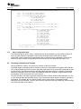
Each PSP driver consists of multiple layers, as shown in Figure A-1. The function of each layer is
described in detail in DM6437/C6424 DSP/BIOS PSP User’s Manual included with the DVSDK installation
for the DM6437/6438 devices, and is summarized here.
Application
DSP/BIOS
DDA Layer
PALOS
DDC Layer
Driver
Components
LLC Layer
Device Hardware
Figure A-1. Structure of a PSP Driver
A.1.1
DDA Layer
The DDA layer serves as the driver's interface to the OS. It translates IOM calls to appropriate, lower-level
(typically DDC) function calls. Its sole purpose is to abstract core driver functionality from the OS.
A.1.2
DDC Layer
The DDC layer is the heart of the driver. It is abstracted from both the OS/application layer (by DDA) and
the hardware layer (by LLC). This arrangement is intended to place only the core driver behavior in DDC,
with device- and OS-specific interaction handled by calls to other layers. Therefore, modifying the DDC
layer should be the only necessary step to alter or enhance driver performance.
14
SPRAAX5 – August 2008
Submit Documentation Feedback
www.ti.com
A.1.3
Overview
LLC Layer
The LLC layer consists of CSL code that interacts directly with the peripheral device. It has no direct
contact with the OS and essentially services the DDC, allowing higher-level control in that layer. LLC is
roughly analogous to the FCSL modules available in older DSPs such as the DM642. However, LLC is not
supported as a stand-alone product.
This layer is not formally included in all PSP drivers. Some drivers perform LLC functionality directly in the
DDC layer. In this case, the DDC is not abstracted from the device, and modularity of the driver is
reduced.
A.1.4
PAL OS
The Platform Abstraction Layer for OS services (PALOS) allows the DDC layer to use basic OS functions,
such as semaphore transactions and interrupt masking. By using PALOS functions instead of directly
calling DSP/BIOS modules, the DDC layer is abstracted from the OS.
PALOS is not implemented within an individual driver. It is a separate library, included with the PSP
installation, that is commonly used by many drivers.
SPRAAX5 – August 2008
Submit Documentation Feedback
Software Migration From TMS320DM642 to TMS320DM648/DM6437
15
IMPORTANT NOTICE
Texas Instruments Incorporated and its subsidiaries (TI) reserve the right to make corrections, modifications, enhancements, improvements,
and other changes to its products and services at any time and to discontinue any product or service without notice. Customers should
obtain the latest relevant information before placing orders and should verify that such information is current and complete. All products are
sold subject to TI’s terms and conditions of sale supplied at the time of order acknowledgment.
TI warrants performance of its hardware products to the specifications applicable at the time of sale in accordance with TI’s standard
warranty. Testing and other quality control techniques are used to the extent TI deems necessary to support this warranty. Except where
mandated by government requirements, testing of all parameters of each product is not necessarily performed.
TI assumes no liability for applications assistance or customer product design. Customers are responsible for their products and
applications using TI components. To minimize the risks associated with customer products and applications, customers should provide
adequate design and operating safeguards.
TI does not warrant or represent that any license, either express or implied, is granted under any TI patent right, copyright, mask work right,
or other TI intellectual property right relating to any combination, machine, or process in which TI products or services are used. Information
published by TI regarding third-party products or services does not constitute a license from TI to use such products or services or a
warranty or endorsement thereof. Use of such information may require a license from a third party under the patents or other intellectual
property of the third party, or a license from TI under the patents or other intellectual property of TI.
Reproduction of TI information in TI data books or data sheets is permissible only if reproduction is without alteration and is accompanied
by all associated warranties, conditions, limitations, and notices. Reproduction of this information with alteration is an unfair and deceptive
business practice. TI is not responsible or liable for such altered documentation. Information of third parties may be subject to additional
restrictions.
Resale of TI products or services with statements different from or beyond the parameters stated by TI for that product or service voids all
express and any implied warranties for the associated TI product or service and is an unfair and deceptive business practice. TI is not
responsible or liable for any such statements.
TI products are not authorized for use in safety-critical applications (such as life support) where a failure of the TI product would reasonably
be expected to cause severe personal injury or death, unless officers of the parties have executed an agreement specifically governing
such use. Buyers represent that they have all necessary expertise in the safety and regulatory ramifications of their applications, and
acknowledge and agree that they are solely responsible for all legal, regulatory and safety-related requirements concerning their products
and any use of TI products in such safety-critical applications, notwithstanding any applications-related information or support that may be
provided by TI. Further, Buyers must fully indemnify TI and its representatives against any damages arising out of the use of TI products in
such safety-critical applications.
TI products are neither designed nor intended for use in military/aerospace applications or environments unless the TI products are
specifically designated by TI as military-grade or "enhanced plastic." Only products designated by TI as military-grade meet military
specifications. Buyers acknowledge and agree that any such use of TI products which TI has not designated as military-grade is solely at
the Buyer's risk, and that they are solely responsible for compliance with all legal and regulatory requirements in connection with such use.
TI products are neither designed nor intended for use in automotive applications or environments unless the specific TI products are
designated by TI as compliant with ISO/TS 16949 requirements. Buyers acknowledge and agree that, if they use any non-designated
products in automotive applications, TI will not be responsible for any failure to meet such requirements.
Following are URLs where you can obtain information on other Texas Instruments products and application solutions:
Products
Amplifiers
Data Converters
DSP
Clocks and Timers
Interface
Logic
Power Mgmt
Microcontrollers
RFID
RF/IF and ZigBee® Solutions
amplifier.ti.com
dataconverter.ti.com
dsp.ti.com
www.ti.com/clocks
interface.ti.com
logic.ti.com
power.ti.com
microcontroller.ti.com
www.ti-rfid.com
www.ti.com/lprf
Applications
Audio
Automotive
Broadband
Digital Control
Medical
Military
Optical Networking
Security
Telephony
Video & Imaging
Wireless
www.ti.com/audio
www.ti.com/automotive
www.ti.com/broadband
www.ti.com/digitalcontrol
www.ti.com/medical
www.ti.com/military
www.ti.com/opticalnetwork
www.ti.com/security
www.ti.com/telephony
www.ti.com/video
www.ti.com/wireless
Mailing Address: Texas Instruments, Post Office Box 655303, Dallas, Texas 75265
Copyright © 2008, Texas Instruments Incorporated


![[U4.43.03] Opérateur AFFE_MATERIAU](http://vs1.manualzilla.com/store/data/006352709_1-66280dcdd9d7ac1974f95651fec4b070-150x150.png)