1
TI-RTOS 1.10
Getting Started Guide
Literature Number: SPRUHD3E
May 2013
Contents
Preface . . . . . . . . . . . . . . . . . . . . . . . . . . . . . . . . . . . . . . . . . . . . . . . . . . . . . . . . . . . . . . . . . . . . . . . . . . . . . . . 3
1
About TI-RTOS . . . . . . . . . . . . . . . . . . . . . . . . . . . . . . . . . . . . . . . . . . . . . . . . . . . . . . . . . . . . . . . . . . . . .
1.1 What is TI-RTOS? . . . . . . . . . . . . . . . . . . . . . . . . . . . . . . . . . . . . . . . . . . . . . . . . . . . . . . . . . . . . . .
1.2 What are the TI-RTOS Components?. . . . . . . . . . . . . . . . . . . . . . . . . . . . . . . . . . . . . . . . . . . . . . . .
1.3 For What Boards and Devices Does TI-RTOS Provide Examples? . . . . . . . . . . . . . . . . . . . . . . . . .
1.4 What Drivers Does TI-RTOS Include? . . . . . . . . . . . . . . . . . . . . . . . . . . . . . . . . . . . . . . . . . . . . . . .
1.5 Hardware Resources Used by TI-RTOS Components . . . . . . . . . . . . . . . . . . . . . . . . . . . . . . . . . . .
1.5.1 TMDXDOCKH52C1 Resources Used . . . . . . . . . . . . . . . . . . . . . . . . . . . . . . . . . . . . . . . . .
1.5.2 TMDXDOCK28M36 Resources Used . . . . . . . . . . . . . . . . . . . . . . . . . . . . . . . . . . . . . . . . .
1.5.3 EK-TM4C123GXL Resources Used . . . . . . . . . . . . . . . . . . . . . . . . . . . . . . . . . . . . . . . . . .
1.5.4 EKS-LM4F232 Resources Used . . . . . . . . . . . . . . . . . . . . . . . . . . . . . . . . . . . . . . . . . . . . .
1.6 For More Information . . . . . . . . . . . . . . . . . . . . . . . . . . . . . . . . . . . . . . . . . . . . . . . . . . . . . . . . . . . .
4
4
5
6
6
7
7
7
8
8
9
2
Installing TI-RTOS . . . . . . . . . . . . . . . . . . . . . . . . . . . . . . . . . . . . . . . . . . . . . . . . . . . . . . . . . . . . . . . . .
2.1 System Requirements . . . . . . . . . . . . . . . . . . . . . . . . . . . . . . . . . . . . . . . . . . . . . . . . . . . . . . . . . .
2.2 Installing Code Composer Studio . . . . . . . . . . . . . . . . . . . . . . . . . . . . . . . . . . . . . . . . . . . . . . . . . .
2.3 Installing TI-RTOS . . . . . . . . . . . . . . . . . . . . . . . . . . . . . . . . . . . . . . . . . . . . . . . . . . . . . . . . . . . . .
2.3.1 Installing on Windows . . . . . . . . . . . . . . . . . . . . . . . . . . . . . . . . . . . . . . . . . . . . . . . . . . . .
2.3.2 Installing on Linux . . . . . . . . . . . . . . . . . . . . . . . . . . . . . . . . . . . . . . . . . . . . . . . . . . . . . . .
12
13
13
14
14
14
3
Examples for TI-RTOS . . . . . . . . . . . . . . . . . . . . . . . . . . . . . . . . . . . . . . . . . . . . . . . . . . . . . . . . . . . . . .
3.1 Creating an Example Project Using the TI Resource Explorer . . . . . . . . . . . . . . . . . . . . . . . . . . . .
3.2 Example Overview . . . . . . . . . . . . . . . . . . . . . . . . . . . . . . . . . . . . . . . . . . . . . . . . . . . . . . . . . . . . .
3.3 Example Settings . . . . . . . . . . . . . . . . . . . . . . . . . . . . . . . . . . . . . . . . . . . . . . . . . . . . . . . . . . . . . .
3.3.1 TMDXDOCKH52C1 Development Board . . . . . . . . . . . . . . . . . . . . . . . . . . . . . . . . . . . . .
3.3.2 TMDXDOCK28M36 Development Board. . . . . . . . . . . . . . . . . . . . . . . . . . . . . . . . . . . . . .
3.3.3 EK-TM4C123GXL Board . . . . . . . . . . . . . . . . . . . . . . . . . . . . . . . . . . . . . . . . . . . . . . . . . .
3.3.4 EKS-LM4F232 Board. . . . . . . . . . . . . . . . . . . . . . . . . . . . . . . . . . . . . . . . . . . . . . . . . . . . .
3.4 Installing USB Drivers for the USB Device Examples. . . . . . . . . . . . . . . . . . . . . . . . . . . . . . . . . . .
3.5 Using Examples for Individual Components . . . . . . . . . . . . . . . . . . . . . . . . . . . . . . . . . . . . . . . . . .
15
16
18
20
20
22
22
23
25
27
4
Configuring TI-RTOS . . . . . . . . . . . . . . . . . . . . . . . . . . . . . . . . . . . . . . . . . . . . . . . . . . . . . . . . . . . . . . .
4.1 Starting the Configuration Tool . . . . . . . . . . . . . . . . . . . . . . . . . . . . . . . . . . . . . . . . . . . . . . . . . . . .
4.2 Configuring TI-RTOS . . . . . . . . . . . . . . . . . . . . . . . . . . . . . . . . . . . . . . . . . . . . . . . . . . . . . . . . . . .
4.3 Configuring Individual Sub-Components . . . . . . . . . . . . . . . . . . . . . . . . . . . . . . . . . . . . . . . . . . . .
28
29
30
31
Index . . . . . . . . . . . . . . . . . . . . . . . . . . . . . . . . . . . . . . . . . . . . . . . . . . . . . . . . . . . . . . . . . . . . . . . . . . . . . . . 32
SPRUHD3E—May 2013
Submit Documentation Feedback
Contents
2
Preface
SPRUHD3E—May 2013
Read This First
About This Manual
This manual describes TI-RTOS. The version number as of the publication of this manual is v1.10.
Notational Conventions
This document uses the following conventions:
•
Program listings, program examples, and interactive displays are shown in a special typeface.
Examples use a bold version of the special typeface for emphasis.
Here is a sample program listing:
#include <xdc/runtime/System.h>
Int main(Void)
{
System_printf("Hello World!\n");
return (0);
}
•
Square brackets ( [ and ] ) identify an optional parameter. If you use an optional parameter, you
specify the information within the brackets. Unless the square brackets are in a bold typeface, do not
enter the brackets themselves.
Trademarks
Registered trademarks of Texas Instruments include Stellaris and StellarisWare. Trademarks of Texas
Instruments include: the Texas Instruments logo, Texas Instruments, TI, TI.COM, C2000, C5000, C6000,
Code Composer, Code Composer Studio, Concerto, controlSUITE, DSP/BIOS, SPOX, Tiva, Tivaware,
TMS320, TMS320C5000, TMS320C6000 and TMS320C2000.
ARM is a registered trademark, and Cortex is a trademark of ARM Limited.
Windows is a registered trademark of Microsoft Corporation.
Linux is a registered trademark of Linus Torvalds.
All other brand or product names are trademarks or registered trademarks of their respective companies
or organizations.
May 10, 2013
SPRUHD3E—May 2013
Submit Documentation Feedback
Read This First
3
Chapter 1
SPRUHD3E—May 2013
About TI-RTOS
This chapter provides an overview of TI-RTOS.
Topic
1.1
Page
1.1
What is TI-RTOS? . . . . . . . . . . . . . . . . . . . . . . . . . . . . . . . . . . . . . . . . . . 4
1.2
What are the TI-RTOS Components? . . . . . . . . . . . . . . . . . . . . . . . . . . 5
1.3
For What Boards and Devices Does TI-RTOS Provide Examples? . . 6
1.4
What Drivers Does TI-RTOS Include? . . . . . . . . . . . . . . . . . . . . . . . . . . 6
1.5
Hardware Resources Used by TI-RTOS Components . . . . . . . . . . . . . 7
1.6
For More Information . . . . . . . . . . . . . . . . . . . . . . . . . . . . . . . . . . . . . . . 9
What is TI-RTOS?
TI-RTOS makes it easier to develop applications for TI
microcontrollers. This product contains several software
components and examples that use these components together.
TI-RTOS is a one-stop solution for developing applications for TI
embedded processors. It provides an OS kernel,
communications support, drivers, and more. It is tightly
integrated with TI’s Code Composer Studio (CCS) development
environment. In addition, examples demonstrate how to use
each supported device and driver. These can be used as a
starting point for your own projects.
SPRUHD3E—May 2013
Submit Documentation Feedback
About TI-RTOS
4
www.ti.com
1.2
What are the TI-RTOS Components?
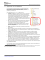
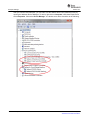
What are the TI-RTOS Components?
TI-RTOS contains its own source files, pre-compiled libraries (both
instrumented and non-instrumented), and examples. Additionally, TIRTOS contains a number of components within its "products"
subdirectory as shown here.
The components in the "products" subdirectory are:
•
SYS/BIOS. SYS/BIOS is a scalable real-time kernel. It is designed
to be used by applications that require real-time scheduling and
synchronization or real-time instrumentation. It provides preemptive
multi-threading, hardware abstraction, real-time analysis, and
configuration tools. SYS/BIOS is designed to minimize memory and
CPU requirements on the target. The FatFs module used by several
examples is part of SYS/BIOS.
•
IPC. This is a component containing packages that are designed to
allow communication between processors in a multi-processor
environment and communication to peripherals. This
communication includes message passing, streams, and linked
lists. These work transparently in both uni-processor and multiprocessor configurations.
•
MWare. The M3 portion of ControlSuite. It includes low level drivers
and examples.1
•
NDK. The Network Developer's Kit (NDK) is a platform for development and demonstration of
network enabled applications on TI embedded processors, currently limited to the TMS320C6000
family and ARM processors.
•
TivaWare. This software is an extensive suite of software designed to simplify and speed
development of Tiva-based microcontroller applications. (TivaWare was previously called
StellarisWare.) This component is rebuilt to include only the portions required by TI-RTOS.1
•
UIA. The Unified Instrumentation Architecture provides target content that aids in the creation and
gathering of instrumentation data (for example, Log data).
•
XDCtools. This component provides the underlying tooling for configuring and building SYS/BIOS,
IPC, NDK, and UIA. TI-RTOS installs XDCtools only if the version needed by TI-RTOS has not
already been installed as part of a CCS or SYS/BIOS installation. If TI-RTOS installs XDCtools, it
places it in the top-level CCS directory (for example, c:\ti), not the TI-RTOS products directory.
To see the release notes for each component, you can select a component in the TI Resource Explorer
under TI-RTOS > Products.
TI-RTOS installs versions of these components that have been reduced in size by removing files that
apply only to device families not supported by TI-RTOS.
1. The MWare and TivaWare libraries distributed with TI-RTOS have been rebuilt with the following compiler option: --define=USE_RTOS.
See the TI-RTOS.README file in the top-level folders of the MWare and TivaWare components of TI-RTOS for details.
SPRUHD3E—May 2013
Submit Documentation Feedback
About TI-RTOS
5
For What Boards and Devices Does TI-RTOS Provide Examples?
1.3
www.ti.com
For What Boards and Devices Does TI-RTOS Provide Examples?
Currently, TI-RTOS provides examples for the following boards:
Family
Board
Device on Board
Concerto
TMDXDOCKH52C1
F28M35H52C1
Concerto
TMDXDOCK28M36
F28M36P63C2
ARM
EK-TM4C123GXL
TM4C123GH6PM
ARM
EKS-LM4F232
TM4C123GH6PGE
Both M3 and 28x sides of Concerto boards are supported.
If you want to use any of these components with other device families, you will need to download and
install the complete component separately. For example, if you want to use SYS/BIOS with a C64x+
device, you will need to download and install the full SYS/BIOS product.
Examples are provided specifically for the supported boards, but libraries are provided for each of these
device families, so that you can port the examples to similar boards. Porting information for TI-RTOS is
provided on the Texas Instruments Embedded Processors Wiki.
1.4
What Drivers Does TI-RTOS Include?
TI-RTOS includes drivers for the following peripherals. These drivers are in the
<install_dir>/packages/ti/drivers directory. TI-RTOS examples show how to use these drivers.
Note that all of these drivers are built on top of MWare and TivaWare.
•
•
•
EMAC. Ethernet driver used by the networking stack (NDK) and not intended to be called directly.
•
SPI. API set intended to be used directly by the application or middleware to communicate with the
Serial Peripheral Interface (SPI) bus. SPI is sometimes called SSI (Synchronous Serial Interface).
•
SDSPI. Driver for SD cards using an SPI (SSI) bus. This driver is used by the FatFS and not intended
to be called directly by the application.
•
•
UART. API set intended to be used directly by the application to communicate with the UART.
•
Other USB functionality. See the USB examples for reference modules that provide support for the
Human Interface Device (HID) class (mouse and keyboard) and Communications Device Class
(CDC). This code is provided as part of the examples, not as a separate driver.
•
Watchdog. API set intended to be used directly by the application or middleware to manage the
watchdog timer.
•
WiFi. Driver used by a Wi-Fi device's host driver to exchange commands, data, and events between
the host MCU and the wireless network processor. Not intended to be called directly.
I2C. API set intended to be used directly by the application or middleware.
GPIO. API set intended to be used directly by the application or middleware to manage the GPIO
interrupts, pins, and ports.
USBMSCHFatFs. USB MSC Host under FatFS (for Flash drives). This driver is used by FatFS and
is not intended to be called directly by the application.
In addition, TI-RTOS provides the following MessageQ transport:
•
6
SPIMessageQTransport. MessageQ transport for the SPI driver for use in multicore applications
that use the IPC component.
About TI-RTOS
SPRUHD3E—May 2013
Submit Documentation Feedback
www.ti.com
1.5
Hardware Resources Used by TI-RTOS Components
Hardware Resources Used by TI-RTOS Components
This section briefly describes which hardware resources TI-RTOS and its dependent components use by
default. Some of these resources offer flexible options, whereas others are fixed in the current design or
implementation.
1.5.1
TMDXDOCKH52C1 Resources Used
The following list shows which TMDXDOCKH52C1 peripheral resources are used by TI-RTOS
applications on that platform. TI-RTOS examples control which peripherals (and which ports) are used.
•
SYS/BIOS. Uses the first general-purpose timer available and that timer’s associated interrupts.
Generally, this will be Timer 0. SYS/BIOS manages the Interrupt Vector Table.
•
•
IPC. Uses the IPC registers including their associated interrupts.
TI-RTOS.
— Ethernet. Uses the EMAC driver and its associated interrupts with the NDK to support
networking.
— SD Card. Uses FatFs and the SDSPI driver on SSI0 without interrupts to read and write to files
on an SD Card.
— EEPROM. Uses the I2C driver on I2C0 with its associated interrupts to read and write to the
onboard EEPROM.
— GPIOs. The GPIO driver is used on 2 onboard LEDs: LD2 (PC6_GPIO70) and LD3
(PC7_GPIO71) as output pins and one pin as an input pin PB4_GPIO12.
— Serial. The UART driver uses UART0 which is attached to the FTDI USB chip to facilitate serial
communications.
— SPI. The SPI driver uses SPI0 for Board SPI0 and SPI1 for Board SPI1.
— SPIMessageQTransport. The master SSI peripheral uses SPI0, and the slave SSI peripheral
uses SPI1.
— USB. The USB reference examples use the USB library and the USB controller with its
associated interrupts.
— Watchdog. The Watchdog driver example uses Watchdog Timer 0 and its associated interrupt.
1.5.2
TMDXDOCK28M36 Resources Used
The following list shows which TMDXDOCK28M36 peripheral resources are used by TI-RTOS
applications on that platform. TI-RTOS examples control which peripherals (and which ports) are used.
•
SYS/BIOS. Uses the first general-purpose timer available and that timer’s associated interrupts.
Generally, this will be Timer 0. SYS/BIOS manages the Interrupt Vector Table.
•
•
IPC. Uses the IPC registers including their associated interrupts.
TI-RTOS.
— Ethernet. Uses the EMAC driver and its associated interrupts with the NDK to support
networking.
— SD Card. Uses FatFs and the SDSPI driver on SSI3 without interrupts to read and write to files
on an SD Card.
— GPIOs. The GPIO driver is used on 2 onboard LEDs: D1 (PE7_GPIO31) and D2 (PF2_GPIO34)
as output pins and one pin as an input pin PB4_GPIO12, pin 58 on the docking station.
— Serial. The UART driver uses UART0 which is attached to the FTDI USB chip to facilitate serial
communications.
SPRUHD3E—May 2013
Submit Documentation Feedback
About TI-RTOS
7
Hardware Resources Used by TI-RTOS Components
www.ti.com
— SPI. The SPI driver uses SPI0 for Board SPI0 and SPI1 for Board SPI1.
— USB. The USB reference examples use the USB library and the USB controller with its
associated interrupts.
— Watchdog. The Watchdog driver example uses Watchdog Timer 0 and its associated interrupt.
1.5.3
EK-TM4C123GXL Resources Used
The following list shows which EK-TM4C123GXL peripheral resources are used by TI-RTOS applications
on that platform. TI-RTOS examples control which peripherals (and which ports) are used.
•
SYS/BIOS. Uses the first general-purpose timer available and that timer’s associated interrupts.
Generally, this will be Timer 0. SYS/BIOS manages the Interrupt Vector Table.
•
TI-RTOS.
— GPIOs. The GPIO driver uses 3 output pins for the onboard RGB LED (R:PF1 G:FP3 B:PF2) and
2 input pins for switches SW1 (PF4) and SW2 (PF0).
— Serial. The UART driver uses UART0 which is attached to the FTDI USB chip to facilitate serial
communications.
— SPI. The SPI driver uses SPI0 for Board SPI0 and SPI3 for Board SPI1.
— USB. The USB reference examples use the USB library and the USB controller with its
associated interrupts. This device only supports USB in device mode.
— Watchdog. The Watchdog driver example uses Watchdog Timer 0 and its associated interrupt.
— WiFi. The WiFi examples for use with the CC3000 use GPIO pins PB2, PB5, and PE0 as well as
the GPIO interrupt for port B. They also use the SPI driver on SSI2 with interrupts and the
associated uDMA channels.
1.5.4
EKS-LM4F232 Resources Used
The following list shows which EKS-LM4F232 peripheral resources are used by TI-RTOS applications on
that platform. TI-RTOS examples control which peripherals (and which ports) are used.
•
SYS/BIOS. Uses the first general-purpose timer available and that timer's associated interrupts.
Generally, this will be Timer 0. SYS/BIOS manages the Interrupt Vector Table.
•
TI-RTOS.
— SD Card. Uses FatFs and the SDSPI driver on SSI0 without interrupts to read and write to files
on an SD Card.
— GPIOs. The GPIO driver is used on the onboard User LED (PG2) as an output pin and on 5 input
pins SW1-SW5 (PM0-4).
— Serial. The UART driver uses UART0 which is attached to the FTDI USB chip to facilitate serial
communications.
— SPI. The SPI driver uses SPI1 for Board SPI0 and SPI3 for Board SPI1.
— USB. The USB reference examples use the USB library and the USB controller with its
associated interrupts.
— Watchdog. The Watchdog driver example uses Watchdog Timer 0 and its associated interrupt.
— WiFi. The WiFi examples for use with the CC3000 use GPIO pins PC7, PH1, and PC6 as well
as the GPIO interrupt for port C. It also uses the SPI driver on SSI3 with interrupts and the
associated uDMA channels.
8
About TI-RTOS
SPRUHD3E—May 2013
Submit Documentation Feedback
www.ti.com
1.6
For More Information
For More Information
To learn more about TI-RTOS and the software components used with it, refer to the following
documentation. In addition, you can select a component in the TI Resource Explorer under TI-RTOS >
Products to see the release notes for that component.
•
TI-RTOS
— TI-RTOS User’s Guide (SPRUHD4)
— SYS/BIOS on TI Embedded Processors Wiki
— BIOS forum on TI’s E2E Community
— TI-RTOS Porting Guide
•
Code Composer Studio (CCS)
— CCS online help
— CCSv5 on TI Embedded Processors Wiki
— Code Composer forum on TI’s E2E Community
•
SYS/BIOS
— SYS/BIOS 6 Getting Started Guide. <sysbios_install>/docs/Bios_Getting_Started_Guide.pdf
— SYS/BIOS User’s Guide (SPRUEX3)
— SYS/BIOS online reference (also called "CDOC").
Open from CCS help or run <sysbios_install>/docs/cdoc/index.html.
— SYS/BIOS on TI Embedded Processors Wiki
— BIOS forum on TI’s E2E Community
— SYS/BIOS 6.x Product Folder
— Embedded Software Download Page
•
XDCtools
— XDCtools online reference. Open from CCS help or run <xdc_install>/docs/xdctools.chm.
— RTSC-Pedia Wiki
— BIOS forum on TI’s E2E Community
— Embedded Software Download Page
•
IPC
— IPC User’s Guide (SPRUGO6)
— IPC online API reference. Run <ipc_install>/docs/doxygen/index.html.
— IPC online configuration reference. Open from CCS help or run
<ipc_install>/docs/cdoc/index.html.
— Embedded Software Download Page
SPRUHD3E—May 2013
Submit Documentation Feedback
About TI-RTOS
9
For More Information
•
www.ti.com
NDK
— NDK User’s Guide (SPRU523)
— NDK Programmer’s Reference Guide (SPRU524)
— NDK on TI Embedded Processors Wiki
— BIOS forum on TI’s E2E Community
— Embedded Software Download Page
•
UIA
— System Analyzer User’s Guide (SPRUH43)
— UIA online reference. Open from CCS help or run <uia_install>/docs/cdoc/index.html.
— System Analyzer on TI Embedded Processors Wiki
— Embedded Software Download Page
•
MWare and ControlSuite
— Documents in <tirtos_install>/products/MWare_##/docs
— ControlSuite on TI Embedded Processors Wiki
— ControlSuite Product Folder
•
TivaWare
— Documents in <tirtos_install>/products/TivaWare_C_Series-1.#/docs
— TivaWare Product Folder
— Online StellarisWare Workshop
•
FatFS API
— Open source documentation
— FatFS for SYS/BIOS wiki page
— SYS/BIOS online reference (also called "CDOC").
Open from CCS help or run <sysbios_install>/docs/cdoc/index.html. Navigate to the
ti.sysbios.fatfs.FatFS module topic in the SYS/BIOS API reference documentation.
•
General microcontroller information
— Microcontrollers forum on TI’s E2E Community
•
Concerto boards and devices
— Concerto F28M35x Technical Reference Manual
— Concerto F28M36x Technical Reference Manual
— C2000 on TI Embedded Processors Wiki
— Concerto on TI Embedded Processors Wiki
— Concerto Product Folder
— H52C1 Concerto Experimenter Kit
— F28M35H52C Concerto Microcontroller datasheets
— H63C2 Concerto Experimenter Kit
— F28M36P63C2 Concerto Microcontroller datasheets
10
About TI-RTOS
SPRUHD3E—May 2013
Submit Documentation Feedback
www.ti.com
•
For More Information
Tiva boards and devices
— Tiva C Series TM4C123G LaunchPad Evaluation Kit
— TM4C123GH6PM Tiva C Series Microcontroller
— EKS-LM4F232 Evaluation Kit
— TM4C123GH6PGE Tiva C Series Microcontroller
•
SD Cards
— Specification
•
I2C
— Specification
•
WiFi
— SimpleLink Wi-Fi CC3000 Wiki
— CC3000 Product Folder
— SimpleLink Wi-Fi SmartConfig Apps
SPRUHD3E—May 2013
Submit Documentation Feedback
About TI-RTOS
11
Chapter 2
SPRUHD3E—May 2013
Installing TI-RTOS
This chapter covers the required steps needed to install and build TI-RTOS.
Topic
Page
2.1
System Requirements. . . . . . . . . . . . . . . . . . . . . . . . . . . . . . . . . . . . . . 13
2.2
Installing Code Composer Studio . . . . . . . . . . . . . . . . . . . . . . . . . . . . 13
2.3
Installing TI-RTOS . . . . . . . . . . . . . . . . . . . . . . . . . . . . . . . . . . . . . . . . . 14
SPRUHD3E—May 2013
Submit Documentation Feedback
Installing TI-RTOS
12
www.ti.com
2.1
System Requirements
System Requirements
The Windows version of TI-RTOS can be installed on systems running Windows 7, Windows Vista, or
Windows XP (SP2 or SP3).
A Linux version of TI-RTOS is also available.
In order to install TI-RTOS, you must have at least 2 GB of free disk space. (If you have not yet installed
Code Composer Studio, you will also need at least 2 GB of disk space for that installation.)
2.2
Installing Code Composer Studio
TI-RTOS is used in conjunction with Code Composer Studio 5.4 or higher.
We strongly recommend that you install CCS in the default installation directory of c:\ti. If you install in
c:\Program Files (or c:\Program Files (x86) with Windows 7), you are likely to run into problems related
to Windows security permissions.
Note:
Do not install CCS in a location that contains any spaces in the full path. For example,
CCS should not be installed in c:\Program Files. Makefiles may not function correctly
with directory paths that include spaces.
To install CCS 5.4, go to the product page at http://www.ti.com/tool/ccstudio and follow a link to download
the software for your license type.
Run the executable installer, and answer the prompts as appropriate. We strongly recommend that you
install CCS in the default installation directory of c:\ti.
When you are prompted for the type of Setup, select "Complete Feature Set".
Note:
TI-RTOS installs a version of SYS/BIOS that may be newer than the version installed
by CCS. For TI-RTOS to work properly, you should use the SYS/BIOS version
delivered with TI-RTOS.
SPRUHD3E—May 2013
Submit Documentation Feedback
Installing TI-RTOS
13
Installing TI-RTOS
2.3
www.ti.com
Installing TI-RTOS
TI-RTOS product comes delivered as an installer that needs to be installed in Code Composer Studio's
installation directory.
2.3.1
Installing on Windows
To install TI-RTOS on a Windows host, follow these steps:
1. Exit from CCS if it is currently open.
2. Download the installer for TI-RTOS. For example, tirtos_setupwin32_1_##_##_##.exe.
3. Run the downloaded file to install the full TI-RTOS product in the directory where CCS 5.4 is installed.
By default, this is c:\ti. This is the recommended location for installing TI-RTOS.
Note: TI-RTOS installs XDCtools only if the version needed by TI-RTOS has not already been
installed as part of a CCS or SYS/BIOS installation. If TI-RTOS installs XDCtools, it places it in the
top-level CCS directory (for example, c:\ti), not the TI-RTOS products subdirectory. Note that this
version has been reduced in size by removing support for target families not supported by TI-RTOS.
4. Start CCS 5.4 or higher.
5. Wait for CCS to scan for newly installed products and display the Extension Sites window to notify
you of the products that have been discovered. You should see the TI-RTOS installation directory
listed (for example, c:\ti\tirtos_1_##_##_## by default). Leave the TI-RTOS item checked, and
click Finish to add it to CCS.
6. You will see a window that asks if you want to restart CCS now. Click Yes.
2.3.2
Installing on Linux
To install TI-RTOS on a Linux host, follow these steps:
1. Exit CCS if it is currently open.
2. Download the installer for TI-RTOS. For example, tirtos_setuplinux_1_##_##_##.bin.
3. You may want to log in as root before performing the installation. It is also possible to run the
installation from your user account.
4. Run the downloaded file to install the full TI-RTOS product. Accept the defaults from the Linux
installer. (The installer detects whether you are running it as user or root.)
Note: TI-RTOS installs XDCtools only if the version needed by TI-RTOS has not already been
installed as part of a CCS or SYS/BIOS installation. If TI-RTOS installs XDCtools, it places it in the
top-level CCS directory, not the TI-RTOS products subdirectory. Note that this version has been
reduced in size by removing support for target families not supported by TI-RTOS.
5. Start CCS 5.4 or higher.
6. Wait for CCS to scan for newly installed products and display the Extension Sites window to notify
you of the products that have been discovered. You should see the TI-RTOS installation directory
listed. Leave the TI-RTOS item checked, and click Finish to add it to CCS.
14
Installing TI-RTOS
SPRUHD3E—May 2013
Submit Documentation Feedback
Chapter 3
SPRUHD3E—May 2013
Examples for TI-RTOS
TI-RTOS comes with a number of examples that illustrate on how to use the individual components. This
chapter explains how to create and use these examples.
Topic
Page
3.1
Creating an Example Project Using the TI Resource Explorer . . . . . 16
3.2
Example Overview. . . . . . . . . . . . . . . . . . . . . . . . . . . . . . . . . . . . . . . . . 18
3.3
Example Settings . . . . . . . . . . . . . . . . . . . . . . . . . . . . . . . . . . . . . . . . . 20
3.4
Installing USB Drivers for the USB Device Examples . . . . . . . . . . . . 25
3.5
Using Examples for Individual Components . . . . . . . . . . . . . . . . . . . 27
SPRUHD3E—May 2013
Submit Documentation Feedback
Examples for TI-RTOS
15
Creating an Example Project Using the TI Resource Explorer
3.1
www.ti.com
Creating an Example Project Using the TI Resource Explorer
TI-RTOS uses TI Resource Explorer within CCS to let you quickly create example projects and open
documentation. Follow these steps to use TI Resource Explorer to create and use TI-RTOS examples:
1. If the TI Resource Explorer tab in CCS is closed, choose View > TI Resource Explorer to open it.
2. Expand the TI-RTOS item in the tree to show the Demo Projects and Example Projects for your
platform.
3. Select an example to create. See Section 3.2, Example Overview and the TI-RTOS User’s Guide
(SPRUHD4) for information about each example.
4. Click the Step 1 link in the right pane of the TI Resource Explorer to Import the example project
into CCS. This adds a new project to your Project Explorer view. A green checkmark is placed next
to each step you have completed for the selected example.
The project created will have a name with the format <example>_<device>.You can expand the
project to view or change the source code and configuration file.
16
Examples for TI-RTOS
SPRUHD3E—May 2013
Submit Documentation Feedback
www.ti.com
Creating an Example Project Using the TI Resource Explorer
5. Click the Step 2 link when you are ready to build the project. If you want to change any build options,
right click on the project and select Properties from the context menu. For example, you can change
compiler, linker, and RTSC (XDCtools) options.
6. When you are ready to debug the example, click the Step 3 link to create a target configuration to
connect with the board.
7. You will see the Debugger Configuration dialog. Choose an emulator from the list. For the F28M3x
devices, choose the Texas Instruments XDS 100v2 USB Emulator. For Tiva devices, choose the
Stellaris In-Circuit Debug Interface.
8. Click the Step 4 link to launch a debug session for the project and switch to the CCS Debug
Perspective. (If you are running a multi-core example, see the "Examples for TI-RTOS" chapter in
the TI-RTOS User’s Guide (SPRUHD4) for instructions for running the example.)
SPRUHD3E—May 2013
Submit Documentation Feedback
Examples for TI-RTOS
17
Example Overview
3.2
www.ti.com
Example Overview
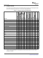
The components and hardware used by the TI-RTOS examples are shown in the following table. Details
about these examples are provided in the TI-RTOS User’s Guide (SPRUHD4).
Table 3-1. Components Used by TI-RTOS Examples
Graphic Library Demo
X
TCP Echo
X
X
TCP Echo for CC3000
X
X
X
X
X
CC3000 Patcher
X
X
X
X
X
UDP Echo
X
X
UDP Echo for CC3000
X
X
X
X
SPI Loopback
X
X
X
FatSD: FatFs File Copy
X
X
X
X
FatSD Raw: FatFs File Copy using FatFs
APIs
X
X
X
X
FatSD USB Copy: (SD Card and USB
Drive)
X
X
X
X
GPIO Interrupt
X
X
X
X
X
2
X
X
X
X
X
X
X
X
X
X
X
X
X
X
X
X
X
X
X
X
X
X
X
X
X
I C EEPROM
X
UART Console *
X
X
X
X
UART Echo
X
X
X
X
UART Logging
X
X
X
X
USB Keyboard Device
X
X
X
X
USB Keyboard Host
X
X
X
X
USB Mouse Device
X
X
X
X
USB Mouse Host
X
X
X
X
USB Serial Device
X
X
X
USB CDC Mouse Device
X
Watchdog
X
X
UIA
X
UART
IPC SPI Master / Slave
WiFi
X
SPI
Demo [M3] / Demo [C28]
I2C
X
CDC
Empty TI-RTOS Project
HID
Example
X
X
X
X
X
X
IPC
NDK / EMAC
Watchdog Timer
GPIO (& LED)
USB MSC Host
USB
Classes
SYS/BIOS
SD Card / SDSPI
FatFS
X
X
X
* UART is used by SysCallback for sending System_printf() and printf() output to a console. Other
examples use SysMin.
18
Examples for TI-RTOS
SPRUHD3E—May 2013
Submit Documentation Feedback
www.ti.com
Example Overview
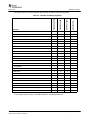
The board for which TI-RTOS examples are provided are shown in the following table.
Empty TI-RTOS Project
X
X
Demo [M3] / Demo [C28]
X
X
IPC SPI Master / Slave
X
X
Graphic Library Demo
TCP Echo
EKS-LM4F232
EK-TM4C123GXL
TMDXDOCK28M36
Example
TMDXDOCKH52C1
Table 3-2. Example Availability by Board
X
X
X
X
TCP Echo for CC3000 *
X
X
CC3000 Patcher *
X
X
X
X
X
X
UDP Echo
X
X
UDP Echo for CC3000 *
SPI Loopback
X
X
FatSD: FatFs File Copy
X
X
X
FatSD Raw: FatFs File Copy using FatFs APIs
X
X
X
FatSD USB Copy: (SD Card and USB Drive)
X
X
X
GPIO Interrupt
X
X
X
X
I2C
X
EEPROM
UART Console
X
X
X
X
UART Echo
X
X
X
X
UART Logging
X
X
X
X
USB Keyboard Device
X
X
X
X
USB Keyboard Host
X
X
USB Mouse Device
X
X
USB Mouse Host
X
X
USB Serial Device
X
X
USB CDC Mouse Device
X
X
Watchdog
X
X
X
X
X
X
X
X
X
X
X
* This example requires either a CC3000 EM board or CC3000 BoosterPack.
SPRUHD3E—May 2013
Submit Documentation Feedback
Examples for TI-RTOS
19
Example Settings
3.3
www.ti.com
Example Settings
There is a separate <example_name>_readme.txt file for each of the examples. These files are added
to your CCS project when you use the TI Resource Explorer to create a project.
The <example_name>_readme.txt files contain the following types of information:
•
•
•
Actions performed by functions in the example.
Hardware-specific descriptions of buttons, LEDs, etc…
Which external components are (or may be) needed to run with particular examples.
The subsections that follow list settings required to run the TI-RTOS examples on the supported boards.
3.3.1
TMDXDOCKH52C1 Development Board
Jumper settings:
•
•
J01-J15: B-C position (Ethernet)
J20-J21: B-C position (I2C EEPROM)
— J6: 2-3 position (I2C EEPROM Write protection off)
•
•
J22-J25: B-C position (SPI/SSI SD Card slot)
J30-J31: B-C position (USB Host and Device)
— A board modification is required for the USB host examples (see Section 3.3.1.2)
Switch settings:
•
SW1: Open all 4 switches by bringing them into the "down" position. This allows the M3 (master
subsystem) to boot out of Flash memory.
•
GPIO12: Some examples use this pin as an input. When shorting this pin to ground (GND), it will
simulate a button press.
SPI Loopback example pin connections:
Master Board Pin (Function)
Slave Board Pin (Function)
02 (SPI0CLK)
24 (SPI1CLK)
03 (SPI0FSS)
25 (SPI1FSS)
04 (SPI0RX)
27 (SPI1TX)
05 (SPI0TX)
26 (SPI1RX)
SPI IPC Master/Slave example pin connections:
20
Examples for TI-RTOS
SPRUHD3E—May 2013
Submit Documentation Feedback
www.ti.com
3.3.1.1
Example Settings
Setting the MAC Address
If you are using the NDK and the EMAC peripheral, you will need to edit the MAC address in the boardspecific C file (for example, TMDXDOCKH52C1.c) in the examples. Modify the following definition in the
file to match the MAC address printed on your board.
/*
* EMAC configuration structure
* Set user/company specific MAC octates. The following sets the address
* to ff-ff-ff-ff-ff-ff. Users need to change this to make the label on
* their boards.
*/
UInt8 macAddress[6] = {0xff, 0xff, 0xff, 0xff, 0xff, 0xff};
For example, the following would set the MAC address to A8-63-F2-00-05-1A:
UInt8 macAddress[6] = {0xA8, 0x63, 0xF2, 0x00, 0x05, 0x1A};
3.3.1.2
USB Host Mode Board Modification
Using the USB controller in host mode on the TMDXDOCKH52C1 requires a hardware modification to
the control card. This modification is not required, but can be performed without causing problems, when
using the USB controller in device mode.
Remove and short resistor R230 on the control card.
This modification allows the USB_VBUS pin to correctly detect the VBUS voltage level; preventing a false
VBUS_ERR from being generated by the USB controller.
SPRUHD3E—May 2013
Submit Documentation Feedback
Examples for TI-RTOS
21
Example Settings
3.3.2
www.ti.com
TMDXDOCK28M36 Development Board
Jumper settings:
•
J2-J7: 1-2 position (USB Host and Device)
Switch settings:
•
•
•
A:SWI: Both switches should be in the ON position
SW1: Place all switches in the 1 (up) position to allow the M3 to boot out of Flash memory.
GPIO 58: Some examples use pin 58 as it is labeled on the docking station as an input. Shorting this
pin to ground (GND) will simulate a button press.
SPI Loopback example pin connections:
3.3.2.1
Master Board Pin (Function)
Slave Board Pin (Function)
71 (SPI0CLK)
75 (SPI1CLK)
73 (SPI0FSS)
77 (SPI1FSS)
69 (SPI0RX)
81 (SPI1TX)
67 (SPI0TX)
79 (SPI1RX)
Setting the MAC Address
If you are using the NDK and the EMAC peripheral, you will need to edit the MAC address in the boardspecific C file (for example, TMDXDOCK28M36.c) in the examples. See Section 3.3.1.1 for details.
3.3.3
EK-TM4C123GXL Board
Jumper settings:
Examples that use the WiFi driver—for example, the TCP Echo and UDP Echo examples for CC3000—
require the CC3000 BoosterPack. This BoosterPack fits over J1 and J2.
Switch settings:
•
•
SW1: Some examples use PF4 as an input.
SW2: Some examples use PF0 as an input
SPI Loopback example pin connections:
22
Master Board Pin (Function)
Slave Board Pin (Function)
PA2 (SPI0CLK)
PD0 (SPI3CLK)
PA3 (SPI0FSS)
PD1 (SPI3FSS)
PA4 (SPI0RX)
PD3 (SPI3TX)
PA5 (SPI0TX)
PD2 (SPI3RX)
Examples for TI-RTOS
SPRUHD3E—May 2013
Submit Documentation Feedback
www.ti.com
3.3.4
Example Settings
EKS-LM4F232 Board
Jumper settings: N/A
Examples that use the WiFi driver—for example, the TCP Echo and UDP Echo examples for CC3000
and the CC3000 Patcher example—require a CC3000 evaluation board with EM headers. The
corresponding EM headers for the EKS-LM4F232 go on the bottom of the board at J9 and J10. They may
not be populated on the evaluation board already.
Switch settings:
•
•
SW3: Some examples use PM2 as an input
SW4: Some examples use PM3 as an input
SPI Loopback example pin connections:
Master Board Pin (Function)
Slave Board Pin (Function)
PF2 (SPI1CLK)
PK0 (SPI3CLK)
PF3 (SPI1FSS)
PK1 (SPI3FSS)
PF0 (SPI1RX)
PK3 (SPI3TX)
PF1 (SPI1TX)
PK2 (SPI3RX)
USB connection and ports:
Connect the power/CDI USB connector on the board to a USB port on your host PC. This connection is
used for both emulation and the serial output. If you would also like to see instrumentation (UIA), also
connect the Host/Device/OTG USB connector on the board to your host PC. See the Stellaris LM4F232
Evaluation Board User’s Manual (SPMU272) for details about USB connectors.
SPRUHD3E—May 2013
Submit Documentation Feedback
Examples for TI-RTOS
23
Example Settings
www.ti.com
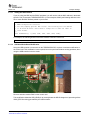
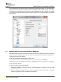
After you connect both USB ports, you can make sure the Stellaris drivers are installed correctly by
opening the Windows Device Manager. To do this, right-click on Computer in Windows Explorer and
select Properties. Choose the Device Manager. You should see a device list similar to the following:
24
Examples for TI-RTOS
SPRUHD3E—May 2013
Submit Documentation Feedback
www.ti.com
Installing USB Drivers for the USB Device Examples
The virtual serial port (in the previous figure, COM4) will be used for serial output. You will need to set up
a terminal emulator to see the console output from the TI-RTOS UART Console example. Use a serial
connection to the Virtual Serial Port of your device, with 115200 bps, 8 data bits, 1 stop bit, and no parity.
For example, if you had the Virtual Serial Port, COM4, using the PuTTY terminal emulator, you would set
it up as follows:
3.4
Installing USB Drivers for the USB Device Examples
The USB examples build upon the examples provide with TivaWare and MWare. Because the examples
mimic the same functionality, you can use the same drivers delivered with standalone installations of
TivaWare and Control Suite (MWare).
In TI-RTOS, the Windows USB drivers are located in the
<tirtos_install>/products/TivaWare_C_Series-1.#/windows_drivers directory.
The Windows menus and dialogs you see may be slightly different from those shown here, depending
on your version of Windows.
To install the USB driver, follow these steps:
1. Load and run a USB device reference example—USB Keyboard Device, USB Mouse Device, or USB
CDC Mouse Device.
2. While the example is running, connect the device to the Windows PC via a USB cable. At this point,
Windows will detect the device and attempt to enumerate it.
SPRUHD3E—May 2013
Submit Documentation Feedback
Examples for TI-RTOS
25
Installing USB Drivers for the USB Device Examples
www.ti.com
3. Open the Windows Device Manager by right-clicking on the My Computer desktop icon or
Computer in the Start Menu and selecting Manage.
4. If you are prompted by a security warning in Windows 7, click Yes.
5. Select the Device Manager category in the left pane.
6. In the center pane, select the unknown driver that you are trying to install. For example, the device
shown here is for the USB CDC driver.
26
Examples for TI-RTOS
SPRUHD3E—May 2013
Submit Documentation Feedback
www.ti.com
Using Examples for Individual Components
7. Right-click on the device, and select Update Driver Software.
8. Select Browse my computer for driver software and browse to the location of the Windows USB
drivers, <tirtos_install>/products/TivaWare_C_Series-1.#/windows_drivers. Make sure
the box to Include subfolders is checked.
9. Click Next to run the installation wizard. If you see a Window Security prompt, click Install.
10. After the driver is installed, you can determine the COM port number for the CDC (Virtual COM Port)
device.
3.5
Using Examples for Individual Components
An "empty" TI-RTOS project is provided in the CCS new project wizard. It contains some common code
excerpts that enable different TI-RTOS components. This example is described in the TI-RTOS User’s
Guide (SPRUHD4).
SPRUHD3E—May 2013
Submit Documentation Feedback
Examples for TI-RTOS
27
Chapter 4
SPRUHD3E—May 2013
Configuring TI-RTOS
This chapter describes how to configure how TI-RTOS and its components will be used by your
application.
Topic
Page
4.1
Starting the Configuration Tool . . . . . . . . . . . . . . . . . . . . . . . . . . . . . . 29
4.2
Configuring TI-RTOS. . . . . . . . . . . . . . . . . . . . . . . . . . . . . . . . . . . . . . . 30
4.3
Configuring Individual Sub-Components . . . . . . . . . . . . . . . . . . . . . . 31
SPRUHD3E—May 2013
Submit Documentation Feedback
Configuring TI-RTOS
28
www.ti.com
4.1
Starting the Configuration Tool
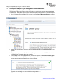
Starting the Configuration Tool
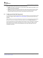
To open the graphical tool for editing configuration files (XGCONF), follow these steps:
1. Make sure you are in the C/C++ perspective of CCS. If you are
not in that perspective, click the C/C++ icon to switch back.
2. Double-click on the *.cfg configuration file for a TI-RTOS
example project in the Project Explorer tree. (See Section 3.1 if
you need to create an example project.) While XGCONF is
opening, the CCS status bar shows that the configuration is
being processed and validated.
3. When XGCONF opens, you see the Welcome sheet for TI-RTOS. This sheet provides links to TIRTOS documentation resources.
4. Click the System Overview button to see a handy overview of the components available through the
TI-RTOS. The green check marks indicate which modules are being used by the application.
5. Click a blue box in the System Overview to go to the Welcome sheet for that component or the
configuration page for a driver.
SPRUHD3E—May 2013
Submit Documentation Feedback
Configuring TI-RTOS
29
Configuring TI-RTOS
Note:
www.ti.com
If the configuration is shown in a text editor instead of XGCONF, close the text editor
window. Then, right-click on the .cfg file and choose Open With > XGCONF. If you are
comfortable editing configuration scripts with a text editor, you can do that. However,
you should not have the file open in both types of editor at the same time.
For details about how to use XGCONF, see Chapter 2 of the SYS/BIOS User’s Guide (SPRUEX3).
4.2
Configuring TI-RTOS
When you open a configuration file in XGCONF, you see a list of
Available Products. The components listed here are the same
components that were checked in the RTSC Configuration Settings
page when you created a new CCS project using one of the TI-RTOS
project templates.
Under the TI-RTOS item, you can select one of the modules listed to
configure it. Most of these modules are peripheral drivers. For each
driver, you can select to use either the instrumented or noninstrumented libraries when linking. The instrumented libraries
process Log events while the non-instrumented libraries do not. See
the section on "Using Instrumented or Non-Instrumented Libraries" in
the TI-RTOS User’s Guide (SPRUHD4) for more information. The
following drivers and transports can be configured:
•
EMAC. Driver for Ethernet with the NDK. See Section 3.3.1.1 for
how to set the MAC address.
•
•
•
GPIO. Driver for the GPIO pins (and therefore the LEDs).
•
•
SPI. Driver for the Serial Peripheral Interface (SPI) bus.
•
•
•
•
UART. Driver for the UART peripheral.
I2C. Driver for the I2C peripheral.
SDSPI. Driver for the SD card using an SPI (SSI) bus and the
FatFS.
SPIMessageQTransport. MessageQ transport for the SPI driver
for use in multicore applications.
USBMSCHFatFs. Driver for the USB MSC Host controller.
Watchdog. Driver for the watchdog timer.
WiFi. Driver to communicate with TI Wi-Fi device such as a SimpleLink Wi-Fi CC3000.
The SysCallback module lets you configure the functions that handle System output—for example,
System_printf() and System_abort(). This module handles transmissions to System output only; it does
not handle responses received. See the chapter on "TI-RTOS Utilities" in the TI-RTOS User’s Guide
(SPRUHD4) for more about the SysCallback module.
30
Configuring TI-RTOS
SPRUHD3E—May 2013
Submit Documentation Feedback
www.ti.com
Configuring Individual Sub-Components
Other SystemSupport implementations are provided with XDCtools.
4.3
•
SysMin stores System_printf() strings in an internal buffer in RAM. SysMin requires RAM, so it not
ideal for devices with minimal RAM.
•
SysStd writes System_printf() strings to STDOUT (the CCS Console window). By default, SysStd
allows System_printf() to be called from Tasks only (not Swis or hardware interrupts); it can be
modified to allow calls from Swis and Hwis, but this impacts real-time performance.
Configuring Individual Sub-Components
For information about configuring individual sub-components of TI-RTOS, see the documentation for that
component. Chapter 2 of the SYS/BIOS User’s Guide (SPRUEX3) provides information about using
XGCONF.
Within XGCONF, you can see the full file path to the version of the component being used by hovering
your mouse cursor over a component in the "Other Products" list in the Available Products area.
The CCS online help lets you access the CDOC reference help for various components. For information
about properties you can configure and instances you can create, scroll down in CDOC to see the
sections with red outlines. (You can use the XDCscript link at the top of each page to skip to the
configuration information.)
SPRUHD3E—May 2013
Submit Documentation Feedback
Configuring TI-RTOS
31
Index
SPRUHD3E—May 2013
Index
A
F
Available Products list 30
building examples 17
F28M35H52C1 6
F28M36P63C2 6
FatFs API
other documentation
Flash drives 6
forum 9
C
G
C28x
support 6
CCS
installation 13
other documentation
CDC device 6
example 18
components 5
Concerto 6
other documentation
resources used 7
configuration 28
graphical editor 29
ControlSuite 5
other documentation
GPIO driver 6
configuration 30
resources used 7, 8
B
9
H
HID device 6
example 18
10
I
10
D
debugging examples
disk space 13
documentation 9
10
17
E
EKS-LM4F232 6, 19
resources used 8
EK-TM4C123GXL 6, 19
resources used 8
EMAC driver 6
configuration 30
resources used 7
Ethernet driver 6
examples 15
building 17
creating projects 16
debugging 17
overview 18
SPRUHD3E—May 2013
Submit Documentation Feedback
I2C driver 6
configuration 30
example 18
resources used 7
installation
CCS 13
directory 13
TI-RTOS 14
instrumented libraries 30
IPC 5
example 18
other documentation 9
resources used 7
SPI driver for multicore applications
6
L
LEDs
managed by GPIO driver
6
M
MAC address
21, 22
Index
32
www.ti.com
MessageQ 6
MSC device 6
multicore applications 6
MWare 5
other documentation 10
N
NDK 5
example 18
MAC address 21, 22
other documentation 10
non-instrumented libraries 30
P
products directory 5
R
readme.txt file
20
T
target configuration file 17
TI-RTOS
other documentation 9
TM4C123GH6PGE 6
TM4C123GH6PM 6
TMDXDOCK28M36 6, 19
resources used 7
TMDXDOCKH52C1 6, 19
resources used 7
U
UART driver 6
configuration 30
resources used 7, 8
UIA 5
example 18
other documentation 10
USB driver
example 18
resources used 7, 8
USBMSCHFatFs driver 6
configuration 30
S
SD driver
example 18
SDSPI driver 6
configuration 30
resources used 7, 8
SPI driver 6
configuration 30
resources used 7, 8
SPIMessageQTransport driver
configuration 30
resources used 7
SPIMessageQTransport transport 6
StellarisWare 5
SYS/BIOS 5
examples 18
other documentation 9
resources used 7
SysCallback module
configuration 30
System Overview configuration 29
system requirements 13
33
Index
W
Watchdog driver 6
configuration 30
resources used 7, 8
WiFi driver 6
configuration 30
resources used 8
wiki 9
X
XDCtools 5
other documentation 9
XGCONF
configuring other components 31
configuring TI-RTOS modules 30
starting 29
SPRUHD3E—May 2013
Submit Documentation Feedback
IMPORTANT NOTICE
Texas Instruments Incorporated and its subsidiaries (TI) reserve the right to make corrections, enhancements, improvements
and other changes to its semiconductor products and services per JESD46, latest issue, and to discontinue any product or service
per JESD48, latest issue. Buyers should obtain the latest relevant information before placing orders and should verify that such
information is current and complete. All semiconductor products (also referred to herein as “components”) are sold subject to TI’s
terms and conditions of sale supplied at the time of order acknowledgment.
TI warrants performance of its components to the specifications applicable at the time of sale, in accordance with the warranty
in TI’s terms and conditions of sale of semiconductor products. Testing and other quality control techniques are used to the extent
TI deems necessary to support this warranty. Except where mandated by applicable law, testing of all parameters of each
component is not necessarily performed.
TI assumes no liability for applications assistance or the design of Buyers’ products. Buyers are responsible for their products
and applications using TI components. To minimize the risks associated with Buyers’ products and applications, Buyers should
provide adequate design and operating safeguards.
TI does not warrant or represent that any license, either express or implied, is granted under any patent right, copyright, mask
work right, or other intellectual property right relating to any combination, machine, or process in which TI components or services
are used. Information published by TI regarding third-party products or services does not constitute a license to use such products
or services or a warranty or endorsement thereof. Use of such information may require a license from a third party under the
patents or other intellectual property of the third party, or a license from TI under the patents or other intellectual property of TI.
Reproduction of significant portions of TI information in TI data books or data sheets is permissible only if reproduction is without
alteration and is accompanied by all associated warranties, conditions, limitations, and notices. TI is not responsible or liable for
such altered documentation. Information of third parties may be subject to additional restrictions.
Resale of TI components or services with statements different from or beyond the parameters stated by TI for that component or
service voids all express and any implied warranties for the associated TI component or service and is an unfair and deceptive
business practice. TI is not responsible or liable for any such statements.
Buyer acknowledges and agrees that it is solely responsible for compliance with all legal, regulatory and safety-related requirements concerning its products, and any use of TI components in its applications, notwithstanding any applications-related information or support that may be provided by TI. Buyer represents and agrees that it has all the necessary expertise to create and
implement safeguards which anticipate dangerous consequences of failures, monitor failures and their consequences, lessen
the likelihood of failures that might cause harm and take appropriate remedial actions. Buyer will fully indemnify TI and its
representatives against any damages arising out of the use of any TI components in safety-critical applications.
In some cases, TI components may be promoted specifically to facilitate safety-related applications. With such components, TI’s
goal is to help enable customers to design and create their own end-product solutions that meet applicable functional safety
standards and requirements. Nonetheless, such components are subject to these terms.
No TI components are authorized for use in FDA Class III (or similar life-critical medical equipment) unless authorized officers of
the parties have executed a special agreement specifically governing such use.
Only those TI components which TI has specifically designated as military grade or “enhanced plastic” are designed and intended
for use in military/aerospace applications or environments. Buyer acknowledges and agrees that any military or aerospace use
of TI components which have not been so designated is solely at the Buyer's risk, and that Buyer is solely responsible for
compliance with all legal and regulatory requirements in connection with such use.
TI has specifically designated certain components as meeting ISO/TS16949 requirements, mainly for automotive use. In any
case of use of non-designated products, TI will not be responsible for any failure to meet ISO/TS16949.
Products
Applications
Audio
www.ti.com/audio
Automotive and Transportation
www.ti.com/automotive
Amplifiers
Data Converters
amplifier.ti.com
dataconverter.ti.com
Communications and Telecom
Computers and Peripherals
www.ti.com/communications
www.ti.com/computers
DLP® Products
DSP
www.dlp.com
dsp.ti.com
Consumer Electronics
Energy and Lighting
www.ti.com/consumer-apps
www.ti.com/energy
Clocks and Timers
Interface
www.ti.com/clocks
interface.ti.com
Industrial
Medical
www.ti.com/industrial
www.ti.com/medical
Logic
Power Mgmt
logic.ti.com
power.ti.com
Security
Space, Avionics and Defense
www.ti.com/security
www.ti.com/space-avionics-defense
Microcontrollers
RFID
microcontroller.ti.com
www.ti-rfid.com
Video & Imaging
www.ti.com/video
OMAP Mobile Processors www.ti.com/omap
TI E2E Community
Wireless Connectivity
www.ti.com/wirelessconnectivity
e2e.ti.com
Mailing Address: Texas Instruments, Post Office Box 655303 Dallas, Texas 75265
Copyright © 2013, Texas Instruments Incorporated