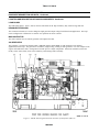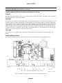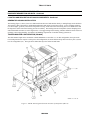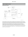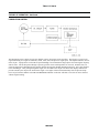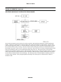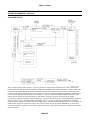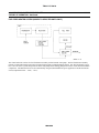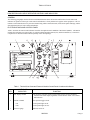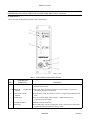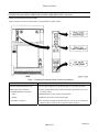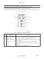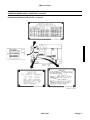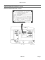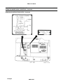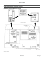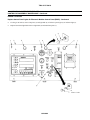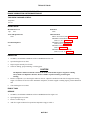
1
ARMY TM 9-6115-730-10
AIR FORCE TO 35C2-3-520-1
MARINE CORPS TM 11598A-OR
NAVAIR 19-50-28
TECHNICAL MANUAL
OPERATOR'S MANUAL
FOR
GENERATOR SET, SKID MOUNTED, TACTICAL QUIET
200 kW, 50/60 Hz
MEP-809A
NSN 6115-01-296-1462
GENERATOR SET, TRAILER MOUNTED, TACTICAL QUIET
200 kW, 50/60 Hz
PU-809A
NSN 6115-01-471-7085
DISTRIBUTION STATEMENT A - Approved for public release; distribution is unlimited.
HEADQUARTERS, DEPARTMENTS OF THE ARMY, AIR FORCE,
NAVY, AND HEADQUARTERS U.S. MARINE CORPS
NAVAIR STATEMENT - Published by Direction of C ommander, Naval Air Systems Co mmand
15 January 2006
PCN 184 115980 03
TM 9-6115-730-10
WARNING SUMMARY
ICONS
The following icons are sometimes used in conjunction with WARNINGs so that you do not miss important information.
They are not meant to be a substitute for reading the WARNINGs, but they give graphic descriptions of dangers.
ELECTRICAL – electrical wire to hand with electricity symbol running through hand shows
that shock hazard exists.
RADIATOR – steam in face and body shows that escaping steam and hot water exist.
EAR PROTECTION – headphones over ears shows that noise level will harm ears.
EXPLOSION – flame and burst shows that material may explode if subjected to high
temperatures, sources of ignition or high pressure.
COLD – hand in touching cold surface shows that the material is extremely cold and can
injure human skin or tissue.
VAPOR – human figure in a cloud shows that vapors, fumes, or exhaust present a danger to
life or cause death.
HOT – hand touching hot surface shows that the surface is extremely hot and can burn
human skin or tissue.
a
TM 9-6115-730-10
WARNING SUMMARY - Continued
This section provides a summary of all critical safety information in this manual. It includes a list of all WARNINGs in work
package procedures. In some cases, WARNINGs on the same subject that are shown separately below are separate
paragraphs under same WARNING heading in work packages.
Prior to starting any work package procedure, the WARNINGs included in the initial setup and text for that work package
must be reviewed and understood.
Also review the MATERIALS/PARTS in the INITIAL SETUP of the work package for hazardous materials used during
maintenance of the equipment. Then, refer to the detailed WARNINGs for hazardous materials listed separately in this
WARNING SUMMARY.
WARNING
Metal jewelry can conduct electricity and become entangled in generator set components. Remove
all metal jewelry when working on generator set. Failure to comply can cause injury or death to
personnel.
WARNING
High voltage is produced when this generator set is in operation. Make sure unit is completely shut
down and free of any power source before attempting any repair or maintenance on the unit. Failure
to comply can cause injury or death to personnel.
WARNING
High voltage is produced when the generator set is in operation. Never attempt to start the generator
set unless it is properly grounded. Failure to comply can cause injury or death to personnel.
WARNING
High voltage is produced when the generator set is in operation. Never attempt to connect or
disconnect load cables while the generator set is running. Failure to comply can cause injury or
death to personnel.
WARNING
DC voltages are present at generator set electrical components even with generator set shut down.
Avoid shorting any positive with ground/negative. Failure to comply can cause injury to personnel
and damage to equipment.
WARNING
Slave receptacle (NATO connector) is electrically live at all times and is unfused. The Battery
Disconnect Switch does not remove power from the slave receptacle. NATO slave receptacle has 24
VDC even when disconnect switch is set to OFF. This circuit is only dead when the batteries are fully
disconnected. Disconnect the batteries before performing maintenance on the slave receptacle.
Failure to comply can cause injury or death to personnel.
b
TM 9-6115-730-10
WARNING SUMMARY Continued
WARNING
High voltage power is available when the main contactor is closed. Avoid accidental contact with
live components. Ensure load cables are properly connected and the load cable door is shut before
closing main contactor. Ensure load is turned off before closing main contactor. Ensure that
soldiers working with/on loads connected to the generator set are aware that main contactor is about
to be closed before closing main contactor. Failure to observe this warning can result in severe
personal injury or death by electrocution.
WARNING
A qualified technician must make the power connections and perform all continuity checks. The
power source may be a generator or commercial power. Failure to comply with this warning can
result in injury or death to personnel.
WARNING
Diesel fuel is flammable and toxic to eyes, skin, and respiratory tract. Skin and eye protection are
required when working in contact with diesel fuel. Avoid repeated or prolonged contact. Provide
adequate ventilation. Operators are to wash exposed skin and change chemical soaked clothing
promptly if exposed to fuel. Failure to comply can cause injury or death to personnel.
WARNING
Fuels used in the generator set are flammable. When filling the fuel tank, maintain metal-to-metal
contact between filler nozzle and fuel tank opening to eliminate static electrical discharge. Failure to
comply can result in flames and possible explosion and can cause injury or death to personnel and
damage to the generator set.
WARNING
Fuels used in the generator set are flammable. Do not smoke or use open flames when performing
maintenance. Failure to comply can result in flames and possible explosion and can cause injury or
death to personnel and damage to the generator set.
WARNING
Hot engine surfaces from the engine and generator circuitry are possible sources of ignition. When
hot refueling with DF-1, DF-2, JP5 or JP8, avoid fuel splash and fuel spill. Do not smoke or use open
flame when performing refueling. Remember PMCS is still required. Failure to comply can result
in flames and possible explosion and can cause injury or death to personnel and damage to the
generator set.
c
TM 9-6115-730-10
WARNING SUMMARY - Continued
WARNING
If necessary to move a generator set that has been operating in parallel with another generator set,
shut down all generator sets prior to removing load cables or ground. Failure to comply can cause
injury or death to personnel by electrocution.
WARNING
Before making any connections for parallel operation or moving a generator set that has been
operating in parallel, ensure there is no input to the load board and the generator sets are shut down.
Failure to comply can cause injury or death to personnel by electrocution.
WARNING
Cooling system operates at high temperature and pressure. Contact with high pressure steam and/or
liquids can result in burns and scalding. Shut down generator set, and allow system to cool before
performing checks, services and maintenance. Failure to comply can cause injury or death to
personnel.
WARNING
Cooling system operates at high temperature and pressure. When performing DURING PMCS,
wear gloves and additional protective clothing and goggles as required. Contact with high pressure
steam and/or liquids can result in burns and scalding.
WARNING
In extreme cold weather, skin can stick to metal. Avoid contacting metal items with bare skin in
extreme cold weather. Failure to comply can cause injury or death to personnel.
WARNING
Operating the generator set exposes personnel to a high noise level. Hearing protection must be
worn when operating or working near the generator set when the generator set is running. Failure
to comply can cause hearing damage to personnel.
WARNING
DO NOT wear loose clothing when performing checks, services and maintenance. Failure to comply
can cause injury or death to personnel.
d
TM 9-6115-730-10
WARNING SUMMARY - Continued
WARNING
When running, generator set engine has hot metal surfaces that will burn flesh on contact. Shut
down generator set, and allow engine to cool before checks, services and maintenance. Wear gloves
and additional protective clothing as required. Failure to comply can cause injury or death to
personnel.
WARNING
When running, generator set engine has hot metal surfaces that will burn flesh on contact. When
performing DURING PMCS, wear gloves and additional protective clothing as required. Failure to
comply can cause injury or death to personnel.
WARNING
Exhaust discharge contains deadly gases including carbon monoxide. Do not operate generator set in
an enclosed area unless exhaust discharge is properly vented outside. Failure to comply can cause
injury or death to personnel.
WARNING
Hot exhaust gases can ignite flammable materials. Allow room for safe discharge of hot gases and
sparks. Failure to comply can cause injury or death to personnel.
WARNING
Exhaust system can get very hot. Shut down generator set, and allow system to cool before
performing checks, services and maintenance. Failure to comply can cause severe burns and injury
to personnel.
WARNING
Exhaust system can get very hot. When performing DURING PMCS, wear gloves and additional
protective clothing as required. Failure to comply can cause severe burns and injury to personnel.
WARNING
When running, winterization heater has hot metal surfaces that will burn flesh on contact. Shut
down generator set and allow heater to cool before performing maintenance. Wear gloves and
additional protective clothing as required. Failure to comply can cause injury or death to personnel.
WARNING
Top housing panels can get very hot. Allow panels to cool down before performing maintenance.
Failure to comply can result in severe burns to personnel.
e
TM 9-6115-730-10
WARNING SUMMARY - Continued
WARNING
Top housing panels can get very hot. When performing DURING PMCS, wear gloves and additional
protective clothing as required. Failure to comply can result in severe burns to personnel.
WARNING
Eye protection is required when working with compressed air. Compressed air can propel particles
at high velocity and injure eyes. Do not exceed 15 psi pressure when using compressed air. Failure
to comply could cause serious injury to personnel.
WARNING
Cleaning compound is toxic. Avoid prolonged breathing of vapors. Use only in a well-ventilated
area. Failure to comply can cause serious injury to personnel.
WARNING
Breathing ether fumes can cause fainting. Do not manually discharge or deliberately inhale ether.
Failure to comply can cause injury to personnel.
WARNING
When disconnecting or removing batteries, disconnect the negative lead that connects directly to the
grounding stud first. Disconnect the negative end of the interconnection cable next. When installing
batteries, reverse the connection sequence. Failure to comply can cause serious personal injury.
WARNING
Batteries give off a flammable gas. Do not smoke or use open flame when performing maintenance.
Failure to comply can cause injury or death to personnel and equipment damage due to flames and
explosion.
WARNING
This manual describes physical and chemical processes that may require the use of chemicals,
solvents, paints, or other commercially available material. Users of the manual should obtain the
material safety data sheets (Occupational Safety and Health Act (OSHA) Form 20 or equivalent)
from the manufacturers or suppliers of materials to be used. Users must be completely familiar with
manufacturer/supplier information and adhere to their procedures, recommendations, warnings,
and cautions for safe use, handling, storage, and disposal of these materials.
FOR FIRST AID, REFER TO FM 4-25.11.
f
TM 9-6115-730-10
CHANGE
NO. 3
HEADQUARTERS,
DEPARTMENTS OF THE ARMY,
AIR FORCE, NAVY,
AND HEADQUARTERS U.S. MARINE CORPS
WASHINGTON, DC, 15 August 2009
TECHNICAL MANUAL
OPERATOR'S MANUAL
FOR
GENERATOR SET, SKID MOUNTED, TACTICAL QUIET
200kW, 50/60 HZ MEP-809A
NSN 6115-01-296-1462
GENERATOR SET, TRAILER MOUNTED, TACTICAL QUIET
200KW, 50/60 HZ PU-809A
NSN 6115-01-471-7085
DISTRIBUTION STATEMENT A: Approved for public release; distribution is unlimited.
TM 9-6115-730-10, dated 15 January 2006, is updated as follows:
1. File this sheet in front of the manual for reference.
2. This change is a result of correcting a grounding procedure in the Generator set manual.
3. New or updated text is indicated by a vertical bar in the outer margin of the page.
4. Remove old pages and insert new pages as indicated below:
Remov e Pages
Insert Pages
Cover/(blank)
A/(B blank)
Cover/(blank)
A/(B blank)
5 Replace the following work packages with their revised version.
Work Package Number
Work Package 5
By Order of the Secretary of the Army:
Official:
JOYCE E. MORROW
Administrative Assistant to the
Secretary of the Army
GEORGE W. CASEY, JR
General, United States Army
Chief of Staff
0923208
By Order of the Secretary of the Air Force:
Official:
NORTON A. SCHWARTZ
General, United States Air Force
Chief of Staff
DONALD J. HOFFMAN
General, United States Air Force
Commander, AFMC
By Order of the Secretary of the Navy:
WALTER H. CANTRELL
Rear Admiral, United States Navy
Commander, Space and Naval Warfare
Systems Command
By Order of the Marine Corps:
G. W. TAYLOR
Product Group Director, PG-15
Ground Transportation Engineer Systems
Marine Corps Systems Command
Army Distribution:
To be distributed in accordance with the initial distribution number (IDN) 256886 requirements
for TM 9-6115-730-10.
Marine Corps Distribution:
To be distributed in accordance with PCN 184 115980 03.
TM 9-6115-730-10
CHANGE
NO. 2
HEADQUARTERS,
DEPARTMENTS OF THE ARMY
AIR FORCE, NAVY,
AND HEADQUARTERS U.S. MARINE CORPS
WASHINGTON, DC, 15 February 2009
TECHNICAL MANUAL
OPERATOR'S MANUAL
FOR
GENERATOR SET, SKID MOUNTED, TACTICAL QUIET
200kW, 50/60 HZ MEP-809A
NSN 6115-01-296-1462
GENERATOR SET, TRAILER MOUNTED, TACTICAL QUIET
200KW, 50/60 HZ PU-809A
NSN 6115-01-471-7085
DISTRIBUTION STATEMENT A: Approved for public release; distribution is unlimited.
TM 9-6115-730-10, dated 15 January 2006, is updated as follows:
1. File this sheet in front of the manual for reference.
2. This change is a result of adding a Unique Identification Plate to the housing of the Generator set.
3. New or updated text is indicated by a vertical bar in the outer margin of the page.
4. Remove old pages and insert new pages as indicated below:
Remove Pages
Insert Pages
Cover/(blank)
A/(B blank)
i and ii
Cover/(blank)
A/(B blank)
i and ii
5 Replace the following work packages with their revised version.
Work Package Number
Work Package 1
Work Package 6
By Order of the Secretary of the Army:
Official:
JOYCE E. MORROW
Administrative Assistant to the
Secretary of the Army
GEORGE W. CASEY, JR
General, United States Army
Chief of Staff
0904302
By Order of the Secretary of the Air Force:
Official:
NORTON A. SWARTZ
General, United States Air Force
Chief of Staff
DONALD J. HOFFMAN
General, United States Air Force
Commander, AFMC
By Order of the Secretary of the Navy:
WALTER H. CANTRELL
Rear Admiral, United States Navy
Commander, Space and Naval Warfare
Systems Command
By Order of the Marine Corps:
G. W. TAYLOR
Product Group Director, PG-15
Ground Transportation Engineer Systems
Marine Corps Systems Command
Army Distribution:
To be distributed in accordance with the initial distribution number (IDN) 256886 requirements
for TM 9-6115-730-10.
Marine Corps Distribution:
To be distributed in accordance with PCN 184 115980 02.
TM 9-6115-730-10
CHANGE
NO. 1
HEADQUARTERS,
DEPARTMENTS OF THE ARMY,
AIR FORCE, and NAVY
Washington, DC, 1 February 2007
TECHNICAL MANUAL
OPERATOR’S MANUAL
FOR
GENERATOR SET, SKID MOUNTED, TACTICAL QUIET
200kW, 50/60 HZ MEP-809A
NSN 6115-01-296-1462
GENERATOR SET, TRAILER MOUNTED, TACTICAL QUIET
200KW, 50/60 HZ PU-809A
NSN 6115-01-471-7085
DISTRIBUTIONSTATEMENT
STATEMENT
DISTRIBUTION
A:
Approved for public release, distribution is unlimited.
TM 9-6115-730-10, dated 15 January 2006 is updated as follows:
1. File this sheet in front of the manual for reference.
2. This change is a result of changes to BII, COEI and AAL list and change to “How to Use” incorporating
changing title of TM 9-6115-730-24 to Field Maintenance Manual.
3. New or updated text is indicated by a vertical bar in the outer margin of the page.
4. Remove old pages and insert new pages as indicated below.
REMOVE PAGES
i - iv
INSERT PAGES
i - iv
5. Replace the following work packages with their revised version.
Work Package Number
Work Package 19
Work Package 20
By Order of the Secretary of the Army:
Official:
JOYCE E. MORROW
Administrative Assistant to the
Secretary of the Army
PETER J. SCHOOMAKER
General, United States Army
Chief of Staff
0635205
By Order of the Secretary of the Air Force:
Official:
JOHN P. JUMPER
General, United States Air Force
Chief of Staff
G EORGE T. BABBITT
General, United States Air Force
Commander, AFMC
By Order of the Secretary of the Navy:
WALTER H. CANTRELL
Rear Admiral, United States Navy
Commander, Space and Naval Warfare
Systems Command
DISTRIBUTION:
To be distributed in accordance with the initial distribution number (IDN) 256884 requirements
for TM 9-6115-730-10.
TM 9-6115-730-10
INSERT LATEST UPDATED PAGES/WORK PACKAGES. DESTROY SUPERSEDED DATA.
LIST OF EFFECTIVE PAGES/WORK PACKAGES
NOTE: The portion of text affected by the updates is indicated by a vertical line in the outer margins of the page.
Updates to illustrations are indicated by miniature pointing hands and/or vertical lines. Updates to wiring
diagrams are indicated by shaded boxes.
Dates of issue for original and updated pages/work packages are:
Original....0....15 January 2006
Change....1....1 February 2007
Change....2....15 February 2009
Change....3....15 August 2009
TOTAL NUMBER OF PAGES FOR FRONT AND REAR MATTER IS 36 AND TOTAL
NUMBER OF WORK PACKAGES IS 23, CONSISTING OF THE FOLLOWING:
Page/WP
No.
*Change
No.
Cover............................... 3
Cover Blank..................... 0
a - f .................................. 0
A ...................................... 3
B Blank ............................ 0
i........................................ 2
ii - iii.................................. 0
iv ...................................... 1
Chp 1 Title Page.............. 0
Chp 1 Index ..................... 0
WP 0001 00 (4 pgs) ........ 2
WP 0002 00 (12 pgs) ...... 0
WP 0003 00 (8 pgs) ........ 0
WP 0004 00 (2 pgs) ........ 0
Chp 2 Title Page.............. 0
Chp 2 Index ..................... 0
WP 0005 00 (18 pgs) ...... 3
WP 0006 00 (38 pgs) ...... 2
WP 0007 00 (6 pgs) ........ 0
Chp 3 Title Page.............. 0
Chp 3 Index ..................... 0
WP 0008 00 (2 pgs)......... 0
WP 0009 00 (8 pgs)......... 0
WP 0010 00 (10 pgs)....... 0
Chp 4 Title Page.............. 0
Page/WP
No.
*Change
No.
WP 0008 00 (2 pgs)......... 0
WP 0009 00 (8 pgs)......... 0
WP 0010 00 (10 pgs)....... 0
Chp 4 Title Page ..............0
Chp 4 Index......................0
WP 0011 00 (2 pgs)......... 0
WP 0012 00 (16 pgs)....... 0
WP 0013 00 (4 pgs)......... 0
WP 0014 00 (4 pgs)......... 0
WP 0015 00 (2 pgs)......... 0
WP 0016 00 (4 pgs)......... 0
WP 0017 00 (2 pgs)......... 0
WP 0018 00 (2 pgs)......... 0
Chp 5 Title Page ..............0
Chp 5 Index......................0
WP 0019 00 (2 pgs)......... 1
WP 0020 00 (10 pgs)....... 1
WP 0021 00 (2 pgs)......... 0
WP 0022 00 (2 pgs)......... 0
WP 0023 00 (4 pgs)......... 0
Glossary-1 - Glossary-2 ... 0
Index-1 - Index-10........... .0
Blank.................................0
Back Cover.......................0
* Zero in this column indicates an original page or work package.
A/(B blank)
Change 3
ARMY TM 9-6115-730-10
AIR FORCE TO 35C2-3-520-1
MARINE CORPS TM 11598A-OR
NAVAIR 19-50-28
HEADQUARTERS
DEPARTMENTS OF THE ARMY,
AIR FORCE, NAVY,
AND HEADQUARTERS U.S. MARINE CORPS
WASHINGTON, DC, 15 JANUARY 2006
TECHNICAL MANUAL
OPERATOR'S MANUAL
FOR
GENERATOR SET, SKID MOUNTED, TACTICAL QUIET
200 kW, 50/60 Hz MEP-809A
NSN 6115-01-296-1462 (EIC: XXX)
GENERATOR SET, TRAILER MOUNTED, TACTICAL QUIET
200 kW, 50/60 Hz PU-809A
NSN 6115-01-471-7085 (EIC: XXX))
DISTRIBUTION STATEMENT A - Approved for public release, distribution is unlimited.
REPORTING ERRORS AND RECOMMENDING IMPROVEMENTS
You can help improve this manual. If you find any mistakes or if you know of a way to improve the procedures,
please let us know. Reports, as applicable by the requiring Service, should be submitted as follows:
(a)
(A) Army - Mail your letter or DA Form 2028 (Recommended Changes to Publications and Blank
Forms) located in the back of this manual, directly to: Commander, U.S. Army CECOM Life Cycle
Management Command (LCMC) Fort Monmouth, ATTN: AMSEL-LC-LEO-E&AS-CM, Fort
Monmouth, NJ 07703-5006. You may also send in your recommended changes via electronic mail
or by fax. Our fax number is 732-532-1556, DSN 992-1556. Our e-mail address is [email protected]. Our online web address for entering and submitting DA
Form 2028s is http://edm.monmouth.army.mil/pubs/2028.html.
(b)
(MC) Marine Corps - Submit notice of discrepancies or suggest changes on a NAVMC 10772.
The NAVMC may be submitted via the Internet using website https://www.ala.usmc.mil, click on
Publications, Technical Publications, follow the instructions, and then click on NAVMC 10772. It
may also be submitted by electronic mail to [email protected], or by mailing a
paper copy NAVMC 10772 in an envelope addressed to Commander, Marine Corps Systems
Command, ATTN: Assistant Commander Acquisition and Logistics (AC LCL/TP), 814 Radford
Blvd, Suite 20343, Albany, Georgia 31704-0343. In addition, forward an information copy to the
Project Officer at the following address: Commander, Marine Corps Systems Command (GTESEPS), 2200 Lester Street, Quantico, VA 22134-6050.
(c)
(N) Navy - By letter directly to Commander, Space and Naval Warfare Systems Command, ATTN:
SPAWAR 8122, Washington, DC 20363-5100.
(d)
(F) Air Force - By Air Force AFTO Form 22 (Technical Manual (TM) Change Recommendation
and Reply) in accordance with paragraph 6-5, Section VI, TO 00-5-1 directly to prime ALC/MST.
A reply will be furnished to you.
i
Change 2
TM 9-6115-730-10
TABLE OF CONTENTS
WP Sequence No. and/or Page No.
WARNING SUMMARY........................................................................................................................................... a
HOW TO USE THIS MANUAL .............................................................................................................................. iii
CHAPTER 1 – INTRODUCTORY INFORMATION WITH THEORY OF OPERATION FOR
200 kW TACTICAL QUIET GENERATOR SET
General Information ............................................................................................................................................. 0001 00
Equipment Description and Data......................................................................................................................... 0002 00
Theory of Operation.............................................................................................................................................. 0003 00
Supporting Data for Repair Parts, Special Tools, TMDE, and Support Equipment ...................................... 0004 00
CHAPTER 2 – OPERATOR INSTRUCTIONS FOR
200 kW TACTICAL QUIET GENERATOR SET
Description and Use of Operator Controls and Indicators................................................................................ 0005
Operation Under Usual Conditions ..................................................................................................................... 0006
Operation Under Unusual Conditions ................................................................................................................. 0007
00
00
00
CHAPTER 3 – OPERATOR TROUBLESHOOTING PROCEDURES FOR
200 kW TACTICAL QUIET GENERATOR SET
Introduction ........................................................................................................................................................... 0008
Malfunction/Symptom Index................................................................................................................................ 0009
Troubleshooting Procedures................................................................................................................................. 0010
00
00
00
CHAPTER 4 – OPERATOR MAINTENANCE INSTRUCTIONS FOR
200 kW TACTICAL QUIET GENERATOR SET
Service Upon Receipt ............................................................................................................................................
Preventive Maintenance Checks and Services (PMCS), Including Lubrication Instructions ........................
Control Box Assembly Maintenance....................................................................................................................
Engine Air Cleaner Maintenance.........................................................................................................................
Engine Cooling System Maintenance...................................................................................................................
Engine Fuel System Maintenance ........................................................................................................................
Engine Lubrication System Maintenance ...........................................................................................................
Preparation for Storage or Shipment ..................................................................................................................
0011 00
0012 00
0013 00
0014 00
0015 00
0016 00
0017 00
0018 00
CHAPTER 5 – SUPPORTING INFORMATION FOR
200 kW TACTICAL QUIET GENERATOR SET
References ..............................................................................................................................................................
Components of End Item (COEI) and Basic Issue Items (BII) Lists ................................................................
Additional Authorized List (AAL) .......................................................................................................................
Expendable and Durable Items List ....................................................................................................................
Warranty Information ..........................................................................................................................................
0019 00
00 20 00
0021 00
0022 00
0023 00
GLOSSARY ............................................................................................................................................................... Glossary-1
INDEX..........................................................................................................................................................
Change 1
ii
Index-1
TM 9-6115-730-10
HOW TO USE THIS MANUAL
This manual contains operator instructions for the 200 kW Tactical Quiet Generator Set (TQG), Skid-Mounted MEP-809A
and for the Tactical Quiet Generator Set, Trailer-Mounted PU-809A. The TQG can be mounted on a 5-ton trailer, Model
XM1061E1. Detailed operation and maintenance information for the trailer is in TM 9-2330-376-14&P.
Refer to References work package WP 0019 00, located in Chapter 5, for a listing of other related manuals.
This Operator's Manual is part of a family of manuals which includes a Unit, Direct Support and General Support
Maintenance Manual (TM 9-6115-730-24) and a Repair Parts and Special Tools Lists (RPSTL) Manual (TM 9-6115-73024P). These manuals implement the Army Maintenance Transformation and change the Maintenance Allocation Chart
(MAC) to support Field and Sustainment Maintenance under the new Two-Level Maintenance Concept.
This manual is written in Work Package (WP) format.
The Table of Contents will help you understand the organization of the manual and will direct you to the major sections. It
lists the specific work packages contained in each chapter. Details such as operational instructions or information about parts
of the TQG can be located by using the index at the end of the manual.
NOTE
The generator end of the TQG is referred to as the REAR of the TQG. The control panel is also located on
the generator end (REAR) of the TQG. Figure 1 (Sheets 1-6) in WP 0002 00 shows where TQG
components are located.
Chapter 1 contains Introductory Information with Theory of Operation. The general information work packages includes the
required maintenance forms, records, and reports; safety, care, and handling; warranty information about the TQG, list of
abbreviations and acronyms, equipment description and data, and theory of operation. The chapter also contains WPs that
describe the equipment and data including location of major components.
Chapter 2 work packages contain Operating Instructions, which include Description and Use of Operator Controls and
Indicators. It also contains operation under usual conditions, to include assembly and preparation for use, installation of
ground rod and load cables, connecting auxiliary fuel hose, initial adjustments before use and self-test, operating procedures,
parallel unit operation (load sharing), and operation under unusual conditions, including operation of winterization kit (issued
to selected units only).
Chapter 3 work packages contain Operator Troubleshooting Procedures. It includes an Introduction WP, a
Malfunction/Symptom Index WP, and operator troubleshooting procedures. Chapter 3, WP 0009 00, Malfunction/Symptom
Index, contains a table listing only the Alarm Codes and Fault Codes for the TQG engine and control systems, including the
Digital Voltage Regulator (DVR). This WP includes the codes that the operator can troubleshoot and take corrective action.
The table also includes the transient codes necessary for the Operator to know in order to notify maintenance to take
corrective action.
Chapter 4 work packages contain Operator Maintenance Instructions, Preventive Maintenance Checks and Services (PMCS),
including Lubrication Instructions that the operator is authorized to perform. It also includes Service Upon Receipt WP,
which contains instructions for reporting preliminary checks and adjustment of the equipment. It also contains information in
a WP for preparation for storage or shipment
Chapter 5 work packages provide information on all related reference material, Components of End Item (COEI) and Basic
Issue Items (BII) List, Additional Authorized List (AAL), and Expendable and Durable Items List. This Chapter also
contains detailed Warranty Information, including manufacturers' warranted list of components.
While performing the procedures in this manual, you may find errors and/or make recommended changes that will improve
the manual. At the back of this manual, you will find copies of DA Form 2028 which invite you to submit your suggestions
digitized or on paper.
iii
Change 1
HOW TO USE THIS MANUAL – Continued
MAINTENANCE WORK PACKAGES
Read the INITIAL SETUP section carefully before you start any maintenance procedure. Get the tools and supplies listed
and the personnel needed.
TITLE
200 kW TACTICAL QUIET GENERATOR
CONTROL BOX ASSEMBLY MAINTENANCE
SUMMARY
THIS WORK PACKAGE COVERS:
Removal,
MAINTENANCE
LEVEL
TOOLS AND
SPECIAL TOOLS
0013 00
Installation
INITIAL SETUP:
REFERENCES
Maintenance Level
Operator
References
TM 9-6115-730-10
WP 0013 00
Tools and Special Tools
Tool kit and supplement, general
mechanic’s, NSN 5180-00-177-7033
Materials/Parts
Corrosion preventive compound
(item 9, WP 0023 00)
MATERIALS/PARTS
Personnel Required
One
PERSONNEL
REQUIRED
LEGEND:
TITLE
The name of the procedure.
SUMMARY
A listing of the general actions to be performed.
MAINTENANCE LEVEL
The level of maintenance authorized to do the procedures.
TOOLS AND SPECIAL TOOLS
The tools and equipment needed to do the procedures.
PERSONNEL REQUIRED
The personnel needed to do the procedures.
REFERENCES
Other work packages, manuals, and publications needed to do the procedure.
MATERIALS/PARTS
The supplies and parts needed to do the procedures.
Change 1
iv
TM 9-6115-730-10
CHAPTER 1
INTRODUCTORY INFORMATION WITH THEORY OF OPERATION
FOR
200 kW TACTICAL QUIET GENERATOR SET
TM 9-6115-730-10
CHAPTER 1
INTRODUCTORY INFORMATION WITH THEORY OF OPERATION
FOR
200 kW TACTICAL QUIET GENERATOR SET
WORK PACKAGE INDEX
Title
WP Sequence No.
GENERAL INFORMATION........................................................................................................................................ 0001 00
EQUIPMENT DESCRIPTION AND DATA ............................................................................................................... 0002 00
THEORY OF OPERATION ......................................................................................................................................... 0003 00
SUPPORTING DATA FOR REPAIR PARTS, SPECIAL TOOLS, TMDE, AND SUPPORT EQUIPMENT .... 0004 00
TM 9-6115-730-10
_____________________________________________________________________________________________
200 kW TACTICAL QUIET GENERATOR SET
0001 00
GENERAL INFORMATION
SCOPE
This technical manual (TM) contains instructions for operation, operator maintenance, checks and adjustments,
theory of operation, troubleshooting, and corrective maintenance for the 200 kW Tactical Quiet Generator Set, MEP809A and PU-809A.
Type of Manual: Operator, crew maintenance.
Model Number and Equipment Name: Generator Set, Skid-Mounted, Tactical Quiet, 200 kW, 50/60 Hz, MEP-809A
and Generator Set, Trailer-Mounted, Tactical Quiet, 200 kW, 50/60 Hz, PU-809A.
Purpose of Equipment: The 200 kW TQG provides 120/208 Vac or 240/416 Vac, 50/60 Hz, 3-phase power for a wide
variety of military applications, offering the mobility and operational characteristics demanded by modern armed
forces. Operational characteristics include the ability to operate at all possible humidity levels, at ambient temperature
levels from –25°F to +120°F (–32°C to 49°C) down to –50°F (–46°C) with winterization kit, and at altitudes up to
10,000 feet.
CONSOLIDATED INDEX OF ARMY PUBLICATIONS AND BLANK FORMS
Refer to the latest issue of DA Pam 25-30 to determine whether there are new editions, changes, or additional
publications pertaining to the equipment.
MAINTENANCE FORMS, RECORDS, AND REPORTS
(1) ( Army) Department of the Army forms and procedures used for equipment maintenance will be those prescribed
by (as applicable) DA PAM 750-8, The Army Maintenance Management System (TAMMS) Users Manual; DA
PAM 738-751, Functional Users Manual for the Army Maintenance Management Systems - Aviation (TAMMS-A);
or AR 700-138, Army Logistics Readiness and Sustainability.
(2) ( Marine Corps) Maintenance forms and records used by Marine Corps personnel are prescribed by TM 470015/1.
(3) ( Air Force) Maintenance forms and records used by Air Force personnel are prescribed in AFI 21-101 and the
applicable TO 00-20 Series Technical Orders.
(4) (Navy) Navy users should refer to their service peculiar directives to determine applicable maintenance forms
and records to be used.
REPORTING OF ITEM AND PACKAGING DISCREPANCIES
Army and Air Force users fill out and forward SF 364 (Supply Discrepancy Report (SDR)) as prescribed in AR 73511-2/DLAR 4140.55/SECNAVINST 4355.18A/AFJ 23-215 4430.3J.
TRANSPORTATION DISCREPANCY REPORT (TDR) (DD 361).
Fill out and forward Transportation Discrepancy Report (TDR) (DD 361) as prescribed by Federal Property
Management Regulation (FPMR), Code of Federal Regulations, Title 41, Chapter 101, Public Contracts and Property
Management.
REPORTING EQUIPMENT IMPROVEMENT RECOMMENDATIONS (EIR)
(1) (Arm y) If your equipment needs improvement, let us know. Send us an EIR. You, the user, are the only one who
can tell us what you don't like about your equipment. Let us know why you don't like the design or performance. If you
have Internet access, the easiest and fastest way to report problems or suggestions is to go to
https://aeps.ria.army.mil/aepspublic.cfm (scroll down and choose the “Submit Quality Deficiency Report” bar). The
Internet form lets you choose to submit an Equipment Improvement Recommendation (EIR), a Product Quality
Deficiency Report (PQDR or a Warranty Claim Action (WCA). You may also submit your information using an SF 368
(Product Quality Deficiency Report). You can send your SF 368 via e-mail, regular mail, or facsimile using the
addresses/facsimile numbers specified in DA PAM 750-8, The Army Maintenance Management System (TAMMS)
Users Manual. We will send you a reply.
0001 00-1
Change 2
TM 9-6115-730-10
_____________________________________________________________________________________________
200 kW TACTICAL QUIET GENERATOR SET
0001 00
GENERAL INFORMATION - Continued
(2) (Air Force) Air Force personnel are encouraged to submit EIR's in accordance with AFR 900-4.
(3) (Navy) Navy personnel are encouraged to submit EIR's through their local Beneficial Suggestion Program.
(4) (Marine Corps) QDR shall be reported on SF 368 in accordance with MCO P4855.10, Product Quality Deficiency
Report Manual. Submit to Commanding General, Marine Corps Logistics Base (Code 850), Albany, Georgia 317045000. A reply will be furnished to you.
CORROSION PREVENTION AND CONTROL (CPC)
Corrosion Prevention and Control (CPC) of Army materiel is a continuing concern. It is important that any corrosion
problems with this item be reported so that the problem can be corrected and improvements can be made to prevent
the problem in future items. Corrosion specifically occurs with metals. It is an electrochemical process that causes
the degradation of metals. It is commonly caused by exposure to moisture, acids, bases, or salts. An example is the
rusting of iron. Corrosion damage in metals can be seen, depending on the metal, as tarnishing, pitting, fogging,
surface residue, and/or cracking. Plastics, composites, and rubbers can also degrade. Degradation is caused by
thermal (heat), oxidation (oxygen), solvation (solvents), or photolytic (light, typically UV) processes. The most
common exposures are excessive heat or light. Damage from these processes will appear as cracking, softening,
swelling, and/or breaking. SF Form 368, Product Quality Deficiency Report should be submitted to the address
specified in DA PAM 750-8, The Army Maintenance Management System (TAMMS) User’s Manual.
DESTRUCTION OF ARMY ELECTRONICS MATERIEL
Destruction of Army electronics materiel to prevent enemy use shall be in accordance with TM 750-244-2.
WARRANTY INFORMATION
See WP 0023 for detailed information concerning the Warranty period and list of warranted components. Report all
defects to your supervisor, who will take appropriate action.
NOMENCLATURE CROSS-REFERENCE LIST
Nomenclature for common names is listed alphabetically with a cross-reference to the official nomenclature (i.e.,
Maintenance Allocation Chart (MAC), Repair Parts and Special Tools Lists (RPSTL)).
Common Name
Official Nomenclature
200 kW TQG
MEP-809A
Generator Set, Skid-Mounted, Tactical Quiet, 200 kW, 50/60 Hz
PU-809A
Generator Set, Trailer-Mounted, Tactical Quiet, 200 kW, 50/60 Hz
LIST OF ABBREVIATIONS/ACRONYMS
Abbreviation/Acronym
Definition
AAL
AC
AMP
ATLASS
AUX
BAT
BIT Built-in-Test
CAGE
CBR
Additional Authorization List
Alternating Current
Ampere
Asset Tracking Logistics and Supply System
Auxiliary
Battery BII Basic Issue Items
Change 2
Commercial and Government Entity
Chemical, Biological, and Radiological
0001 00-2
TM 9-6115-730-10
200 kW TACTICAL QUIET GENERATOR SET
GENERAL INFORMATION - Continued
LIST OF ABBREVIATIONS/ACRONYMS - Continued
Abbreviation/Acronym
CCW Counterclockwise
COEI
CPC
CTA
CW Clockwise
DC Direct
DVR
ECM
EMI Electrom
EMCP
ESD Electrostatic
GFE
GFCI
GND Ground
GSC
Hz
kPa KiloPascal
KVAR Kilovolt-am
0001 00
Definition
Components of End Item
Corrosion Prevention and Control
Common Table of Allowances
Current
Digital Voltage Regulator
Engine Control Module
agnetic Interference
Electronic Modular Control Panel
Discharge
Government Furnished Equipment
Ground Fault Circuit Interrupter
Generator Set Control
Hertz (cycles per second)
pere-reactive
KVARHr Kilovolt-am
pere-reactive hour
kVA Kilovolt-am
pere
kWh Kilowatt
hour
kW Kilowatt
JTA
LCD
LED
MAC
MTOE
NATO
NBC
PF Power
PMCS
PN Part
PQDR
RPSTL
SDR
SOS
TAMMS
Joint Table of Allowances
Liquid Crystal Display
Light Emitting Diode
Maintenance Allocation Chart
Modified Table of Organization and Equipment
North Atlantic Treaty Organization
Nuclear, Biological, and Chemical
Factor
Preventive Maintenance Checks and Services
Number
Product Quality Deficiency Report
Repair Parts and Special Tools Lists
Supply Discrepancy Report
Source of Supply
The Army Maintenance Management System
TDA
TDR Transportation
TM Technical
Table of Distribution and Allowances
Discrepancy Report
Manual
0001 00-3
Change 2
TM 9-6115-730-10
200 kW TACTICAL QUIET GENERATOR SET
GENERAL INFORMATION - Continued
0001 00
LIST OF ABBREVIATIONS/ACRONYMS - Continued
Abbreviation/Acronym
TMDE
TQG
U/M
ULLS
USEPA
Vac
Vdc
Definition
Test Measurement and Diagnostic Equipment
Tactical Quiet Generator
Unit of Measure
Unit Level Logistics System
U. S. Environmental Protection Agency
Volts Alternating Current
Volts Direct Current
SAFETY, CARE, AND HANDLING
The TQG contains no radioactive components or parts or radioactive material requiring special handling or consideration.
The TQG contains no electronic modules or components requiring special handling to protect them from electrostatic
discharge (ESD).
This manual describes physical and chemical processes that may require the use of chemicals, solvents, paints, or other
commercially available material. Users of the manual should obtain the material safety data sheets (Occupational Safety and
Health Act (OSHA) Form 20 or equivalent) from the manufacturers or suppliers of materials to be used. Users must be
completely familiar with manufacturer/supplier information and adhere to their procedures, recommendations, warnings, and
cautions for safe use, handling, storage, and disposal of these materials.
Change 2
0001 00-4
TM 9-6115-730-10
200 kW TACTICAL QUIET GENERATOR SET
EQUIPMENT DESCRIPTION AND DATA
0002 00
EQUIPMENT CHARACTERISTICS, CAPABILITIES, AND FEATURES
The 200 kW Tactical Quiet Generator (TQG) is skid-mounted and is designated MEP-809A. When the 200 kW TQG is
mounted on a trailer, it is designated PU-809A. The TQG consists of a diesel engine that can operate using diesel fuel, or
aviation fuel, a brushless AC generator, a digital voltage regulator (DVR), an electronic governing system, a fuel system, a
24 Vdc cranking system, a control system, a protection system, and other devices as described below to achieve a complete
engine driven generator set. The system uses the Caterpillar C-12 engine and a Marathon generator model DOD 751 FR.
The engine is electronically controlled. The electronic control is essential to meeting U.S. Environmental Protection Agency
(USEPA) and fuel consumption requirements. All the electrical components and assemblies (including the voltage regulator)
that provide the required instrumentation and control functions are contained in the Electronic Modular Control Panel
(EMCP) located on the generator end (REAR) of the TQG as shown in figure 1, sheet 3. Opening the EMCP and side access
panels gives access to all the electrical components and essential engine components. Paralleling receptacles are used to
connect the paralleling cable between generator sets of the same family. The generator set family includes a 100 kW TQG.
The 100 kW TQG is skid-mounted and is designated MEP-807A. When the 100 kW TQG is mounted on a trailer, it is
designated PU-807A. The 100kW generator sets (MEP-807A and PU-807A) use the same control system as the 200kW
generator sets (MEP-809A and PU-809A) and can operate in parallel to share an electrical load.
LOCATION AND DESCRIPTION OF MAJOR COMPONENTS
ENGINE
The engine for the 200 kW TQG is the Caterpillar Model C-12 engine (figure 1, sheet 1, item 1). The engine is
electronically controlled. The Engine Control Module (ECM) controls the amount of fuel that is injected by the unit
injectors. The EMCP provides frequency (speed) control, controls long and short-term stability, and accommodates load
conditions. High injection pressures help to reduce fuel consumption and emissions. Precise injection timing optimizes
engine performance for starting, emissions, noise and fuel consumption.
MUFFLER
The muffler (2) and exhaust tubing are connected to the engine and turbocharger. This system reduces engine exhaust noise.
Exhaust gases are exhausted upward from the top of the generator set.
TURBOCHARGER
The turbocharger (3) is located on the right side of the engine. Powered by engine exhaust gases, the turbocharger
compresses air from the air filter to provide pressurized air to the engine for combustion.
AIR CLEANER ASSEMBLY
The air cleaner assembly (4) is located on the left side of the engine (4) inside the rear access doors. The air cleaner filters
intake air used for engine combustion.
ALTERNATOR
The alternator (5) is located on the right side of the engine. The alternator maintains the batteries in a state of full charge.
The alternator also provides 24 Vdc voltage for TQG control circuits and to the NATO slave receptacle.
RADIATOR
The radiator (6) located at the front of the TQG eliminates engine heat via circulated coolant and air. The radiator and
engine fan are the primary heat exchanger for cooling engine coolant and for turbocharged engine intake air.
WATER PUMP
The water pump (7) located on the right side of the engine circulates coolant through the engine block and radiator to cool
the engine.
0002 00-1
TM 9-6115-730-10
200 kW TACTICAL QUIET GENERATOR SET
EQUIPMENT DESCRIPTION AND DATA - Continued
LOCATION AND DESCRIPTION OF MAJOR COMPONENTS - Continued
Figure 1. 200 kW Tactical Quiet Generator Location of Components (Sheet 1 of 6)
0002 00-2
0002 00
TM 9-6115-730-10
200 kW TACTICAL QUIET GENERATOR SET
EQUIPMENT DESCRIPTION AND DATA - Continued
0002 00
LOCATION AND DESCRIPTION OF MAJOR COMPONENTS - Continued
LOAD BOARD
The load board (figure 1, sheet 2, item 8) connects load cables to the TQG with heavy duty connector lugs and nuts.
RECONNECTION BOARD
The reconnection board (9) is used to change the TQG generator output voltage for different load applications. The TQG
can be configured for 120/208 Vac or 240/416 Vac operation for 50 Hz or 60 Hz.
MAIN CONTACTOR
The main contactor K1 (10) controls generator load output to the load.
AC GENERATOR
The generator (11) used in the 200 kW TQG is Marathon Electric model DOD 751 FR, designed to meet military
applications for the TQG. The generator is a brushless, single bearing, rotating-rectifier generator. It is close-coupled to the
engine via flexible drive disks. Each generator is made up to five major components: main stator (armature), main rotor
(field), exciter stator (field), exciter rotor (armature), and rotating rectifier assembly.
Figure 1. 200 kW Tactical Quiet Generator Location of Components (Sheet 2)
0002 00-3
TM 9-6115-730-10
200 kW TACTICAL QUIET GENERATOR SET
EQUIPMENT DESCRIPTION AND DATA - Continued
0002 00
LOCATION AND DESCRIPTION OF MAJOR COMPONENTS - Continued
ELECTRONIC MODULAR CONTROL PANEL
The TQG EMCP (figure 1, sheet 3, item 12) contains controls and indicators for monitoring TQG operation. Located at the
rear end of the generator set, the EMCP contains the Generator Set Control (GSC) (13), an alarm module (14), and a Digital
Voltage Regulator (DVR) (15). EMCP displays and indicators allow the operator to monitor all engine and generator
functions with alarm and identification of malfunctions. The Malfunction/Symptom Index in WP 0009 00 lists all of the
alarm codes and fault codes for TQG malfunctions. The GSC monitors the output frequency of the generator and controls
the engine speed to maintain a constant output frequency, regardless of load. The PUSH TO STOP EMERGENCY STOP
pushbutton (16) shuts down the TQG immediately when it is pushed.
PARALLELING RECEPTACLES
The PARALLELING RECEPTACLES panel is located to the left of the EMCP. The paralleling receptacles (17) are used to
connect the paralleling cable for multiple 100kW or 200 kW TQG sets of same mode. A 200kW TQG set (MEP-809A and
PU-809A) may be paralleled with a 100kW TQG set (MEP-807A or PU-807A).
CONVENIENCE RECEPTACLES
Two convenience receptacles (18) are located to the left of the EMCP on the PARALLELING RECEPTACLES panel. The
receptacles rated 120 Vac, 15A are available at all times during generator operation. The receptacles are protected by a
GROUND FAULT CIRCUIT INTERRUPTER with TEST and RESET (19) functions. The frequency at the convenience
receptacle outlets is set by generator frequency and will be 50 Hz or 60 Hz.
DEAD CRANK SWITCH
The DEAD CRANK SWITCH (figure 1, sheet 4, item 21) is located inside the generator housing at the left rear. During
maintenance, the dead crank switch allows the engine to be cranked without starting the engine.
NATO SLAVE RECEPTACLE
The NATO slave receptacle (22) is located on the left side (front) of the TQG. It is used for 24 Vdc slave starting.
BATTERIES
Four sealed 12 Vdc batteries (23) located at the front of the generator are connected in series and parallel. The batteries
provide power for EMCP controls, engine starting, and to the NATO slave receptacle. These batteries can be disconnected
with the Battery Disconnect Switch (24).
WINTERIZATION KIT (ISSUED TO SELECTED UNITS ONLY))
The winterization kit consists of a fuel-fired heater (25) to heat engine coolant and connecting control wiring and tubes. The
kit also includes resistor heaters located in EMCP. The fuel-fired heater is controlled with the winterization kit control panel
(figure 1, sheet 3, item 20).
0002 00-4
TM 9-6115-730-10
200 kW TACTICAL QUIET GENERATOR SET
EQUIPMENT DESCRIPTION AND DATA - Continued
LOCATION AND DESCRIPTION OF MAJOR COMPONENTS - Continued
Figure 1. 200 kW Tactical Quiet Generator Location of Components (Sheet 3)
0002 00-5
0002 00
TM 9-6115-730-10
200 kW TACTICAL QUIET GENERATOR SET
EQUIPMENT DESCRIPTION AND DATA - Continued
LOCATION AND DESCRIPTION OF MAJOR COMPONENTS - Continued
Figure 1. 200 kW Tactical Quiet Generator Location of Components (Sheet 4)
0002 00-6
0002 00
TM 9-6115-730-10
200 kW TACTICAL QUIET GENERATOR SET
EQUIPMENT DESCRIPTION AND DATA - Continued
0002 00
LOCATION AND DESCRIPTION OF MAJOR COMPONENTS - Continued
STARTER
The engine starter motor (figure 1, sheet 5, 26) is located on the left rear side of the engine. The electric starter engages the
flywheel mechanically to start the diesel engine.
SKID BASE
The skid base (27) provides the main structural support for the engine and generator. The skid base consists primarily of two
formed side rails, cross members, mounting pads, forklift openings, and a bottom plate. Main cross members complete the
primary skid base structure to support the engine and generator mounting pads and vibration isolators and reinforce the fork
lift openings (28). Four 25,000 lb (11,400 kg) capacity LIFT/TIEDOWN rings (28) are attached to the skid base frame. In
addition to supporting the engine generator assembly, housing, battery and other components, the skid base has provisions
for engine oil drain (30), coolant drain (opposite side), a water separator drain (31), and fuel tank drain (32). The skid base
also serves as a support and protective enclosure for the fuel tank.
FUEL TANK
The fuel tank (33) is a 128 gallon (485L) molded tank located below the diesel engine between the skid assembly side
members.
ENGINE CONTROL MODULE
The ECM (34) monitors most of the engine sensors and controls the fuel injectors and engine timing functions.
Figure 1. 200 kW Tactical Quiet Generator Location of Components (Sheet 5)
0002 00-7
TM 9-6115-730-10
200 kW TACTICAL QUIET GENERATOR SET
EQUIPMENT DESCRIPTION AND DATA - Continued
0002 00
LOCATION AND DESCRIPTION OF MAJOR COMPONENTS - Continued
GENERATOR HOUSING INSTALLATION
The housing (figure 1, sheet 6, item 34) is fabricated from sheet steel and attaches directly to mating flanges on the skid base.
The housing is thus removable for unscheduled maintenance and engine or generator removal. Access openings and doors
(36) allow engine, generator, and external component servicing. Each side of the rear housing has a set of double doors and
the large doors at the front of the housing provide accessibility. The housing structure incorporates acoustic damping foam
and internal baffle structures to reduce engine noise. The rugged design of the housing, includes stiffened corners and access
openings to meet transportability, operational, and handling requirements of a mobile military generator set.
TRAILER-MOUNTED CONFIGURATION (PU-809A)
The skid-mounted TQG can be mounted on a model XM1061E1 5-ton trailer (37). In this configuration, the TQG can be
towed and positioned as required. In the power-unit configuration, the trailer-mounted TQG has an accessory box (38) and
two fire extinguishers (39). The TQG skid is bolted directly to the trailer bed and frame.
Figure 1. 200 kW Tactical Quiet Generator Location of Components (Sheet 6)
0002 00-8
TM 9-6115-730-10
200 kW TACTICAL QUIET GENERATOR SET
EQUIPMENT DESCRIPTION AND DATA - Continued
0002 00
EQUIPMENT DATA
Table 1 lists equipment data for the 200 kW TQG.
Table 1. 200 kW TQG Equipment Data.
EQUIPMENT DATA
200 kW Tactical Quiet Generator Set
MEP-809A
Overall length
Width
Height
Weight
Wet (includes fuel)
Dry
114 in. (290 cm)
50 in. (127 cm)
75 in. (191 cm)
Engine
Manufacturer
Model
Type
Horsepower
Displacement
Valves per cylinder
Valve lash setting (cold engine)
9300 lb (4218 kg)
8200 lb (3719 kg)
Caterpillar
0116-2110
Six cylinder, in-line, four cycle, turbocharged diesel
395 hp @ 1800 rpm (60 Hz)
329 hp @ 1500 rpm (50 Hz)
732 in3 (12.0L)
Four (two inlet, two exhaust)
Inlet: 0.015 in. (0.38 mm)
Exhaust: 0.025 in. (0.64 mm)
Cooling system
Type
Capacity
Normal operating temperature
Temperature indicating system voltage
Pressurized radiator and coolant pump
42 qt (39.7L)
170°F to 200°F (77°C to 93°C)
24 Vdc, range programmable
Lubricating system
Type
Pump type
Capacity
Normal operating pressure
Full flow, circulating pressure
Positive displacement gear
36 qt (34.1L)
35 to 70 psi (241 to 483 kPa)
Fuel
system
Fuel type
Fuel tank capacity
Consumption rate
DF-1, DF-2, JP5, JP8
128 gal (485L)
8 hour tank capacity at full load
Auxiliary fuel pump
Manufacturer
Voltage rating
Delivery rate
Walbro Corp.
24 Vdc (16 to 30 Vdc)
34 gph at 30 Vdc; 17 gph at 18 Vdc
0002 00-9
TM 9-6115-730-10
200 kW TACTICAL QUIET GENERATOR SET
EQUIPMENT DESCRIPTION AND DATA - Continued
0002 00
EQUIPMENT DATA - Continued
Table 1. 200 kW TQG Equipment Data – Continued.
EQUIPMENT DATA
Fuel level switch
Manufacturer
Type
Voltage
Madison
Float
24 Vdc
Engine starting system
Batteries
Manufacterer
Optima
12 Vdc, qty 4 (sealed units)
Starter
Manufacturer
Model
Voltage rating
Drive type
Caterpillar
6V0890
24 Vdc
Direct
Alternator
Manufacturer
Model
Voltage rating
Drive type
Caterpillar
4N3986
24 Vdc
Belt
Generator
Manufacturer
Model
Type
Marathon
DOD 751 FR
Alternating current, synchronous, brushless
Load capacity
200 kW at 60 Hz
(1,800 rpm)
Current ratings
120/208 Vac connection
240/416 Vac connection
60 Hz 50
694A 578A
347A 289A
Power factor
Cooling
Drive type
Duty classification
0.8
Fan cooled
Direct coupling
Continuous
Governing
system
Load measuring unit
Manufacturer
Model
Woodward
9907-175
0002 00-10
167 kW at 50 Hz
(1,500 rpm)
Hz
TM 9-6115-730-10
200 kW TACTICAL QUIET GENERATOR SET
EQUIPMENT DESCRIPTION AND DATA - Continued
0002 00
EQUIPMENT DATA - Continued
Table 1. 200 kW TQG Equipment Data – Continued.
EQUIPMENT DATA
Electronic control module
Manufacturer
Model
Caterpillar
137-7392
GSC Protective Relay Setpoint Values
Low oil pressure shutdown
High water (coolant) temperature shutdown
Engine overspeed
Overcrank (total cycle crank time)
High oil temperature shutdown
Overvoltage alarm threshold
Generator overvoltage shutdown threshold
Generator undervoltage alarm threshold
Generator undervoltage shutdown threshold
Generator overfrequency alarm threshold
Generator overfrequency shutdown threshold
Generator underfrequency alarm threshold
Generator underfrequency shutdown
Generator phase overcurrent alarm threshold
Generator total overcurrent alarm threshold
Generator phase overcurrent shutdown threshold
Generator total overcurrent shutdown threshold
Reverse power shutdown
30 psi (207 kPa)
230° F (110° C)
2120 rpm
90 seconds
253° F (123° C)
125% overvoltage for programmed voltage
125% of nameplate voltage
82% of programmed voltage
75% of nameplate voltage
63 Hz for 60 Hz operation; 53 Hz for 50 Hz operation
66 Hz for 60 Hz operation; 55 Hz for 50 Hz operation
57 Hz for 60 Hz operation; 48 Hz for 50 Hz operation
54 Hz for 60 Hz operation; 45 Hz for 50 Hz operation
160% of nameplate current
160% of nameplate current
160% of nameplate current
160% of nameplate current
15% to 17%
0002 00-11/(12 blank)
TM 9-6115-730-10
200 kW TACTICAL QUIET GENERATOR SET
THEORY OF OPERATION
0003 00
GENERAL
This work package contains functional descriptions of the generator set and explains how TQG functional systems interact
with one another.
ENGINE STARTING SYSTEM
The engine starting system consists of four 12-volt batteries connected in series and parallel, a 24 Vdc starter, a 24 volt
battery charging alternator, a magnetic pickup (for sensing engine speed) and the related switches and relays (described
below) required for control of the starting system. The PUSH TO STOP EMERGENCY STOP pushbutton on the EMCP will
automatically disable the starting system and shut down the TQG if it is pushed in. For engine cranking, battery power is
supplied to the starter motor through the starter solenoid which in turn is controlled by the EMCP. The starter engages the
engine flywheel causing the engine to turn over. As the engine accelerates above crank speed (sensed by a magnetic pickup),
the EMCP disengages the starter. The starting sequence may also be stopped by moving the ENGINE CONTROL switch on
the EMCP to COOL DOWN STOP. The engine may be cranked without starting using the DEAD CRANK switch. The
DEAD CRANK SWITCH is a three-position switch. Up position is CRANK, the center position is OFF, and the lower
position is NORMAL (operation). With the DEAD CRANK SWITCH in CRANK position, the starter motor is energized
without activating any other starting or control function. With the switch in the OFF center position, the system is off. With
the switch in the NORMAL (operation) position, the TQG will crank and start. The batteries are charged by the belt-driven
engine alternator. The belt-driven battery charging alternator also supplies GSC power. Normal operating indication
depends on the state of charge in the batteries. A low charge, such as exists immediately after engine starting, will cause
a high reading. Cold outside temperatures make starting the engine difficult. To improve engine starting in cold weather,
the engine contains an ether start. The ether start is described in the Air Intake and Exhaust System paragraph.
0003 00-1
TM 9-6115-730-10
200 kW TACTICAL QUIET GENERATOR SET
THEORY OF OPERATION - Continued
0003 00
ENGINE STARTING SYSTEM - Continued
The DC battery system provides 24 Vdc for engine starting and TQG control circuits. The four sealed 12 Vdc batteries are
charged by the engine alternator. The DC AMMETER on EMCP indicates alternator charging rate. Battery condition is
also shown on the EMCP lower display ENGINE METER function. Charge rate is shown from -25 amperes to +50
amperes in 5 ampere increments. Normal operating indication depends on the state of charge in the batteries. A low
charge such as exists immediately after engine starting, will cause a high reading. The battery system includes a manually
operated Battery Disconnect Switch to isolate the batteries from the engine. The Battery Disconnect Switch can be used to
remove DC power from the TQG. Battery condition is also shown on the EMCP lower display ENGINE METER function.
The batteries connect directly to the 24 Vdc NATO slave receptacle.
FUEL SYSTEM
0003 00-2
TM 9-6115-730-10
200 kW TACTICAL QUIET GENERATOR SET
THEORY OF OPERATION - Continued
0003 00
FUEL SYSTEM - Continued
The fuel system consists of hoses, steel injector piping, fuel tank, fuel filter/water separator, transfer pump, and injectors.
The transfer pump draws fuel from the fuel tank through a fuel filter/water separator that removes water and small
impurities. The fuel is then pushed through the secondary fuel filter that removes even smaller particles from the fuel.
The fuel then enters a fuel manifold servicing unit injectors. Through the cam-actuated injectors fuel enters the diesel
engine combustion chamber, where it is mixed with air and ignited. The fuel that is not used is cooled and returned to the
fuel tank via an excess fuel return line. When the fuel level is low, the fuel level switch will either supply power to the
external auxiliary fuel pump for external fuel supply or shut down the TQG to prevent it from completely running out of
fuel. If a diesel engine runs out of fuel, it is necessary to fill the fuel filters, purge all air from the lines and pumps, and
bleed all injectors, one at a time.
AUXILIARY FUEL PUMP
The auxiliary fuel system consists of an external fuel supply, fuel filter, piping, a 24 Vdc auxiliary fuel pump and a fuel
level float switch. When the EMCP AUX FUEL switch is ON the auxiliary fuel pump is enabled to transfer fuel from the
external fuel supply to the generator fuel tank. The fuel level float switch shuts off the auxiliary fuel pump when the
generator fuel tank is full and reactivates the pump as the level drops. The fuel level indicator indicates fuel level of
generator fuel tank from empty (E) full to (F).
0003 00-3
TM 9-6115-730-10
200 kW TACTICAL QUIET GENERATOR SET
THEORY OF OPERATION - Continued
0003 00
ENGINE COOLING SYSTEM
The engine cooling system consists of a radiator, hoses, thermostat, surge tank, expansion tank, water pump, a belt driven
fan, and cooling jackets. The water pump forces coolant through passages (cooling jackets) in the engine block and cylinder
head where the coolant absorbs heat from the engine. When the engine reaches normal operating temperature, the thermostat
opens and the heated coolant flows through the upper radiator hose assembly into the radiator. The cooling fan circulates air
through the radiator where the coolant temperature is reduced. In addition, the fan cools engine and generator set
components within the TQG housing by drawing in air from outside the housing through the baffles, circulating the air
through the housing, and forcing the air through the radiator and out through the housing exhaust vents on the roof. The
housing is designed to operate with the doors closed which ensures that the main alternator and other TQG components have
access to a good flow of cooling air from outside the generator set. A coolant temperature sensor provides automatic engine
shut down in the event that coolant temperature exceeds 230°F (110°C). The lower Generator Set Control (GSC) display
indicates the engine coolant temperature.
0003 00-4
TM 9-6115-730-10
200 kW TACTICAL QUIET GENERATOR SET
THEORY OF OPERATION - Continued
0003 00
LUBRICATION SYSTEM
The lubrication system consists of an oil pan, dipstick, pump, oil pressure sender, and filter. The oil pan is a reservoir for
engine lubricating oil. Engine oil lubricates, cleans, cools, seals, and preserves engine parts. The dipstick indicates oil level
in the oil pan. A pump draws oil from the oil pan and through a screen that blocks large objects from entering the oil pump
and oil cooler. The oil then passes through a spin-on type filter where small impurities are removed. From the filter, oil
enters the engine and is distributed to the engine’s internal moving parts through internal passageways. Oil is also supplied
to the turbocharger. After passing through the engine, the oil returns to the oil pan. The lower GSC display indicates oil
pressure sensed by the oil pressure sender in the engine. The engine will shut off automatically if the oil pressure drops
below 30 psi (207 kPa) and the red LOW OIL PRESSURE indicator on the GSC will flash. The oil level can be checked
with the engine running.
0003 00-5
TM 9-6115-730-10
200 kW TACTICAL QUIET GENERATOR SET
THEORY OF OPERATION - Continued
0003 00
AIR INTAKE AND EXHAUST SYSTEM WITH TURBOCHARGER
The air intake and exhaust system consists of an air filter assembly, intake manifold, turbocharger, exhaust manifold and
muffler. Ambient air is drawn into the air filter assembly where it passes through the air cleaner element. Airborne dirt is
removed and trapped in the element. A restriction indicator, located on the air cleaner assembly housing, displays red when
the air cleaner element requires servicing. The inner air filter element retaining nut contains a second restriction indicator
that changes from green to red as air flow is restricted. Filtered air is drawn out of the air cleaner assembly through air intake
tubes to the turbocharger where it is forced through the radiator aftercooler coil. This pressurized air enters the intake
manifold to the combustion chambers where it is mixed with fuel from the injectors. When cold weather starting is required,
ether is injected into the air intake manifold to initiate combustion. When the engine is running, exhaust gases are released
into the exhaust manifold and then to the turbocharger. The exhaust gases drive the turbocharger forcing large amounts of
air into the intake manifold. After passing through the turbocharger, the exhaust gases are channeled into a muffler to
deaden the sound.
0003 00-6
TM 9-6115-730-10
200 kW TACTICAL QUIET GENERATOR SET
THEORY OF OPERATION - Continued
0003 00
AC POWER OUTPUT
The AC output system consists primarily of the AC generator, the output load terminal board, the voltage reconnection
terminal board, the main load contactor and the AC CIRCUIT INTERRUPTER switch on the EMCP. Power created by the
AC generator is supplied through the voltage reconnection terminal board and the main load contactor to the output load
terminals on the output load terminal board. The voltage reconnection terminal board allows configuration of the generator
set for 120/208 volt connections or 240/416 volt connections. The AC CIRCUIT INTERRUPTER switch located on the
EMCP closes and opens the main load contactor. This enables or interrupts the power flow between the voltage
reconnection terminal board and the output load terminals. The main load contactor is also opened automatically during any
of the specified set faults. The DVR module in the EMCP senses AC generator output voltage and provides excitation
voltage to the AC generator to maintain the desired output voltage. The VOLTAGE adjust potentiometer is connected to the
DVR to allow the operator to adjust the voltage. The operator can use the GSC keypad AC METER key to select which
output load terminals to monitor for current and voltage measurements. The values and terminals are indicated on the upper
and lower displays.
0003 00-7
TM 9-6115-730-10
200 kW TACTICAL QUIET GENERATOR SET
THEORY OF OPERATION - Continued
0003 00
FUEL-FIRED HEATER SYSTEM (ISSUED TO SELECTED UNITS ONLY)
The winterization kit consists of a fuel-fired heater assembly with an internal water pump. The fuel-fired heater assembly
preheats coolant and internal water pump circulates heated engine coolant through the engine. The fuel-fired heater system
uses a 24 Vdc electric system that powers the heater fuel pump and circulating pump and a resistor circuit that warms EMCP
components. The EMCP resistors are also automatically energized when EMCP has power applied to it and the thermostat
closes (temperature below …20°F (…29°C).
0003 00-8
TM 9-6115-730-10
200 kW TACTICAL QUIET GENERATOR SET
0004 00
SUPPORTING DATA FOR REPAIR PARTS, SPECIAL TOOLS, TMDE, AND SUPPORT EQUIPMENT
COMMON TOOLS AND TEST EQUIPMENT
For authorized common tools and equipment, refer to the Modified Table of Organization and Equipment (MTOE), Common
Table of Allowances (CTA) 50-970, Expendable/Durable Items (Except: Medical, Class V, Repair Parts, and Heraldic
Items), or Army Medical Department Expendable/Durable Items CTA 8-100, as applicable to your unit.
SPECIAL TOOLS, TMDE, AND SUPPORT EQUIPMENT
Special Tools; Test, Measure, and Diagnostic Equipment (TMDE); and support equipment are not authorized to operators.
These are needed for unit and direct support maintenance. They are listed in the Repair Parts and Special Tools List
(RPSTL) and in the Maintenance Allocation Chart (MAC) in TM 9-6115-730-24.
REPAIR PARTS
Repair parts are listed in TM 9-6115-730-24P (RPSTL).
0004 00-1/(2 blank)
TM 9-6115-730-10
CHAPTER 2
OPERATOR INSTRUCTIONS
FOR
200 kW TACTICAL QUIET GENERATOR SET
TM 9-6115-730-10
CHAPTER 2
OPERATOR INSTRUCTIONS
FOR
200 kW TACTICAL QUIET GENERATOR SET
WORK PACKAGE INDEX
Title
WP Sequence No.
DESCRIPTION AND USE OF OPERATOR CONTROLS AND INDICATORS................................................... 0005 00
OPERATION UNDER USUAL CONDITIONS.......................................................................................................... 0006 00
OPERATION UNDER UNUSUAL CONDITIONS.................................................................................................... 0007 00
TM 9-6115-730-10
200 kW TACTICAL QUIET GENERATOR SET
DESCRIPTION AND USE OF OPERATOR CONTROLS AND INDICATORS
0005 00
GENERAL
The following paragraphs contain references and illustrations that show the location and function of each control and
indicator for operation of the TQG. Each control and indicator is clearly labeled as it appears on the equipment. Call-out
numbers on the illustrations are keyed to the tabular listing which contains the name, based on the panel markings, and the
functional description of each control and indicator.
ELECTRONIC MODULAR CONTROL PANEL
Table 1 describes the controls and indicators located on the TQG Electronic Modular Control Panel (EMCP). The EMCP
includes the Generator Set Control (GSC) (1), Digital Voltage Regulator (DVR) (10), and alarm module (9). These three
components are illustrated and described separately in this work package.
6
6a
CAUTION
ENSURE SYNC MODE SWITCH
IS IN “OFF” POSITION
PRIOR TO STARTING SET
OFF
Table 1. Tactical Quiet Generator Electronic Modular Control Panel Controls and Indicators.
KEY
CONTROL OR
INDICATOR
FUNCTION
1
GSC display module
GSC monitors generator operation and controls engine speed to maintain a
constant 50 or 60 Hz output, regardless of load. Refer to Table 2 for controls
and indicators.
2
PANEL LIGHTS
Two-position toggle switch.
3
ON
Control panel lights are lit.
OFF
Control panel lights are out.
Fuel level gauge
Indicates fuel level.
0005 00-1
Change 3
TM 9-6115-730-10
200 kW TACTICAL QUIET GENERATOR SET
DESCRIPTION AND USE OF OPERATOR CONTROLS AND INDICATORS …Continued
0005 00
ELECTRONIC MODULAR CONTROL PANEL …Continued
Table 1. Tactical Quiet Generator Electronic Modular Control Panel Controls and Indicators…Continued.
KEY
4
5
6
6a
CONTROL OR
INDICATOR
DC AMMETER
FREQUENCY adjust knob
SYNC MODE switch label
SYNC MODE switch
FUNCTION
Indicates DC current from engine alternator.
Potentiometer permits adjustment of generator set frequency.
Cautions user to ensure sync mode switch is in off postion prior to starting.
Four-position switch used to control TQG paralleling operations and modes. If
not in paralleling mode, switch should be OFF.
OFF
Disables synchronizing and synchroscope functions.
SEMI-AUTO
With PARALLEL switch closed (up), GSC brings TQG in synchronization with
load bus and holds it there indefinitely. AC CIRCUIT INTERRUPTER switch
is enabled and operator can connect TQG to others. Automatic voltage
matching is not enabled.
AUTO
Provides complete automatic paralleling with another unit.
Bus Live: GSC brings TQG into sync with load bus and sends a signal to
connect TQG to load bus.
Bus Dead: GSC adjusts voltage to programmed value and connects output to
load automatically.
PERMISSIVE
With PARALLEL switch closed (up), manual paralleling mode allows operator
to adjust voltage, frequency, and phase of TQG to match load bus. When TQG
is synchronized with bus, operator brings TQG on line by closing AC
CIRCUIT INTERRUPTER switch.
7
VOLTAGE adjust knob
Potentiometer control permits fine adjustment of generator set voltage.
8
PARALLEL/UNIT switch
Two-position toggle switch. Controls dead bus monitoring and paralleling of
load sharing modules.
PARALLEL
Activates paralleling circuits (up). Used when placing TQG in parallel mode.
Bus is monitored by relays that will not allow generator output to be connected
to load if there is power on load bus. Load sharing module is connected to
paralleling cable connector for paralleling in ISOCHRONOUS mode.
UNIT
Deactivates paralleling circuits (down). Generator is operating independently of
other generators. GSC monitors bus and load can be connected automatically
or enabled for operator connection. Load sharing module is disconnected from
paralleling cable connector output.
9
Alarm module
Alarm will sound if an overcurrent, an overload, or a low fuel condition exists.
Refer to Table 3.
10
DVR
DVR provides excitation to control and regulate generator voltage. Refer to
Table 4 for controls and indicators.
Change 3
0005 00-2
TM 9-6115-730-10
200 kW TACTICAL QUIET GENERATOR SET
DESCRIPTION AND USE OF OPERATOR CONTROLS AND INDICATORS- Continued
0005 00
ELECTRONIC MODULAR CONTROL PANEL - Continued
Table 1. Tactical Quiet Generator Electronic Modular Control Panel Controls and Indicators…Continued.
KEY
11 AC
CONTROL OR
INDICATOR
CIRCUIT
INTERRUPTER switch
CLOSED
FUNCTION
Three-position toggle switch.
Up momentary toggle activates circuits to close load contactor. Connects TQG
to load.
Press-to-test green indicator is lit when load contactor is closed.
Normal
Toggle switch spring loaded to return to this position.
OPEN
Down momentary toggle activates circuits to open load contactor. Disconnects
TQG from load.
Press-to-test green indicator is off when load contactor is open.
12
Press-to-test green indicator
Indicator lights when AC CIRCUIT INTERRUPTER switch is set to CLOSED.
Indicator off when AC CIRCUIT INTERRUPTER switch is set to OPEN.
13
PUSH TO STOP
EMERGENCY STOP
pushbutton switch
Press for emergency stop of TQG. Switch pulled out for normal operations.
Switch can be reset by turning knob to right and pulling out.
14
BATTLE SHORT switch
Two-position toggle switch. Hinged red safety cover must be raised to set to
ON.
15
16
ON
Disables all safety or protective devices except short circuit and overspeed.
Disables starting of engine. Yellow LED on GSC is lit.
OFF
Normal operation of generator set. Lowering red cover returns switch to OFF.
ENGINE CONTROL switch
Four-position rotary switch.
OFF/RESET
Engine shuts down and fault indicators and overload/short circuit module are
reset, except in emergency stop while EMERGENCY STOP pushbutton is in.
AUTO
Allows remote start/stop control.
MANUAL START
Starts and runs generator set diesel engine.
COOL DOWN/STOP
Shuts engine down after 5-minute cool down period has passed.
AUX FUEL switch
Two-position switch controls auxiliary fuel pump.
ON
Turns on auxiliary fuel pump to supply fuel from external fuel supply.
OFF
Only allows fuel to be consumed from generator set fuel tank.
0005 00-3
Change 3
TM 9-6115-730-10
200 kW TACTICAL QUIET GENERATOR SET
DESCRIPTION AND USE OF OPERATOR CONTROLS AND INDICATORS - Continued
0005 00
GENERATOR SET CONTROL
Table 2 describes the EMCP GSC indicator lights and light emitting diode (LED) displays.
Table 2. Generator Set Control Controls and Indicators.
CONTROL OR
INDICATOR
FUNCTION
1
LOW OIL PRESSURE
shutdown indicator
Red indicator flashes when oil pressure drops below the programmed low oil pressure
setpoints. Engine shuts down and does not run until fault is corrected.
2
EMERGENCY STOP
shutdown indicator
Red indicator flashes when PUSH TO STOP EMERGENCY STOP pushbutton is
pressed on control panel. Engine shuts down and does not start until pushbutton is
pulled out and ENGINE CONTROL switch is set to OFF/RESET and back to
AUTO or MANUAL START. PUSH TO STOP EMERGENCY STOP pushbutton
switch can be reset by turning knob to right or pulling out.
3
HIGH WATER TEMP
shutdown indicator
Red indicator flashes when engine coolant temperature rises above programmed
setpoint for high coolant temperature shutdown. Engine shuts down and does not
start until fault is corrected.
KEY
Change 3
0005 00-4
TM 9-6115-730-10
200 kW TACTICAL QUIET GENERATOR SET
DESCRIPTION AND USE OF OPERATOR CONTROLS AND INDICATORS - Continued
0005 00
GENERATOR SET CONTROL - Continued
Table 2. Generator Set Control Controls and Indicators – Continued.
CONTROL OR
INDICATOR
FUNCTION
4
ENGINE OVERSPEED
shutdown indicator
Red indicator flashes when engine speed rises above programmed setpoint for engine
overspeed. Engine shuts down and does not start until fault is corrected.
5
OVERCRANK
shutdown indicator
Red indicator flashes when engine does not start within programmed setpoint for total
cycle crank time. Engine not allowed to start until fault is corrected.
KEY
NOTE
Indicator lights (key 6 thru 8) perform dual functions depending on
the position of the UNIT/PARALLEL switch.
When UNIT/PARALLEL switch is set to UNIT (FUNCTION I),
the indicators display the following.
FUNCTION I
6
LOW COOLANT
LEVEL indicator
Yellow light flashes when coolant level drops below probe of coolant loss sensor.
Engine shuts down and does not start until fault is corrected.
7
BATTLE SHORT
indicator
Yellow indicator lights when BATTLE SHORT switch is set to ON. Indicates TQG
is operating in battle short condition.
8
IN 50 Hz MODE
Yellow indicator lights when TQG is in 50 Hz mode.
NOTE
When UNIT/PARALLEL switch is set to PARALLEL
(FUNCTION II), the indicators display the following:.
FUNCTION II
6
~ V (left side of light)
Yellow indicator flashes in paralleling mode until TQG and paralleling bus voltages
are within acceptable limits. Yellow indicator lights when voltages match.
7
HZ (left side of light)
Yellow indicator flashes in paralleling mode until TQG and paralleling bus
frequencies are within acceptable limits. Yellow indicator lights when frequencies
match.
8
light)
(left side of
Yellow indicator flashes in paralleling mode until TQG and paralleling bus phases
are within acceptable limits. Yellow indicator lights when phases match.
9
FAULT SHUTDOWN
indicator
Red indicator flashes when GSC detects a fault that is a shutdown fault. If engine is
running, it is shut down. The engine will not start. A diagnostic code is displayed
on upper GSC display (11). Diagnostic codes are described in Chapter 3,
Troubleshooting.
10
FAULT ALARM
indicator
Yellow light flashes when GSC detects an alarm fault. Alarm fault does not cause
engine status to change and engine will continue to run. If engine was not started,
it may be started. A diagnostic code is displayed on upper GSC display (11) when
ALARM CODES (17) key at bottom of GSC is pressed. Diagnostic codes are
described in Chapter 3, Troubleshooting.
0005 00-5
Change 3
TM 9-6115-730-10
200 kW TACTICAL QUIET GENERATOR SET
DESCRIPTION AND USE OF OPERATOR CONTROLS AND INDICATORS - Continued
0005 00
GENERATOR SET CONTROL - Continued
Table 2. Generator Set Control Controls and Indicators…Continued.
CONTROL OR
INDICATOR
KEY
11 Upper
display
(Normal Operation)
Upper
12
display
(Synchroscope for
Parallel Operation)
Lower display
(Normal Operation)
Change 3
FUNCTION
Shows AC voltage, current, and frequency of one phase of generator output. Each
phase can be viewed one at a time by pushing AC METER key (14)at bottom of
GSC. Upper display also displays diagnostic codes for system faults. Refer to
Keypad descriptions (13 thru 19) for more information.
NOTE
Active during paralleling only.
In paralleling modes, upper display toggles between bus and incoming generator
phase C-A voltage and frequency. Right side display shows bUS or GEn. Pressing
AC METER key (14) stops cycle.
When POWER METER key (13) is pressed, displays values for power metering.
When ENGINE METER key (15) is pressed, displays system battery voltage, engine
hours, engine speed, engine oil pressure, and engine coolant temperature. Each
value is shown for two seconds. A small pointer that lines up with the icon for the
condition indicates the value shown. Refer to Keypad description for more
information.
0005 00-6
TM 9-6115-730-10
200 kW TACTICAL QUIET GENERATOR SET
DESCRIPTION AND USE OF OPERATOR CONTROLS AND INDICATORS - Continued
0005 00
GENERATOR SET CONTROL - Continued
Table 2. Generator Set Control Controls and Indicators – Continued.
KEY
CONTROL OR
INDICATOR
FUNCTION
NOTE
Active during paralleling only.
Lower display
(Synchroscope for
Parallel Operation)
Rotating
clockwise
Frequency of incoming generator is greater than load bus.
Rotating
counterclockwise
Frequency of incoming generator is less than load bus.
Stopped in any
position other than top
center
Frequency of incoming generator and load bus are the same. Phases are different.
IN SYNC
center
13-19
13
During paralleling operations, lower display operates as synchroscope in SEMI
AUTO and PERMISSIVE settings of SYNC MODE switch (6). A square symbol
revolves around perimeter of display to indicate phase angle and frequency
relationships between bus and incoming generator. Yellow indicator lights for
three fault alarms also show status of paralleling. Synchronizing lights indicate that
voltages match ~V (6), that frequencies are matched HZ (7), and that phases are
(8). Indicator lights flash speed is relative to speed of
matched
synchroscope symbol.
Stopped at top
Keypad
POWER METER
Frequency of incoming generator and load bus are the same. In phase
(phase angle is 0 ).
Used to control information shown on upper display and lower display.
Displays power data to lower display. When pressed, following functions scroll
automatically:
Total real power (kW)
Total reactive power (KVAR)
Percentage of rated power (%kW)
Power factor (average) (PF)
Display scrolling stops when operator presses key for less than 5 seconds. Display
will show a particular parameter continuously.
0005 00-7
Change 3
TM 9-6115-730-10
200 kW TACTICAL QUIET GENERATOR SET
DESCRIPTION AND USE OF OPERATOR CONTROLS AND INDICATORS - Continued
0005 00
GENERATOR SET CONTROL - Continued
Table 2. Generator Set Control Controls and Indicators…Continued.
KEY
CONTROL OR
INDICATOR
FUNCTION
Additional functions will scroll if key held for more than 5 seconds:
Total real power (kW)
Real power phase A (kW)
Real power phase B (kW)
Real power phase C (kW)
Total apparent power (kVA)
Total reactive power (kVA)
Percentage of rated power (%kW)
Power factor (average) (PF)
Power factor phase A
Power factor phase B
Power factor phase C
Total energy output (kWh)
Total reactive energy output (kVARHr)
14
AC METER
Selects phase of generator output that is shown on upper display. Pressing this key
allows operator to check voltage, current, and frequency of each phase one at a
time. Options are as follows:
Voltage (average), frequency, current (total)
Voltage (line to line), frequency, current (line) for any one phase
Voltage (line to line) for all three phases at once
Current (line) for all three phases at once
Voltage (line to neutral) for all three phases at once
15
ENGINE METER
Stops scrolling of engine condition data shown on lower display. Pointer flashes to
indicate that scrolling is stopped. Pressing key again resumes scrolling. Sequence
of reported data is as follows:
Fuel filter run hours
Oil filter run hours
Battery voltage
Engine run hours
Engine rpm
Engine oil pressure
Engine coolant temperature
16
LAMP TEST
Performs lamp test on GSC. Eight fault indicators are on continuously and all
segments of upper display and lower display are on.
17
ALARM CODES
If FAULT ALARM light is flashing, pressing this key displays diagnostic code
(WP 0009 00) in upper display. Pressing key again resumes display of generator
output information. If FAULT ALARM light is off, this key has no function.
18
EXIT
Service Mode. FOR MAINTENANCE PERSONNEL USE ONLY.
19
SERVICE MODE
Service Mode. FOR MAINTENANCE PERSONNEL USE ONLY.
Change 3
0005 00-8
TM 9-6115-730-10
200 kW TACTICAL QUIET GENERATOR SET
DESCRIPTION AND USE OF OPERATOR CONTROLS AND INDICATORS - Continued
0005 00
ALARM MODULE
Table 3 describes the EMCP alarm module controls and indicators.
Table 3. Alarm Module Controls and Indicators.
KEY
CONTROL OR
INDICATOR
1
OVERCURRENT indicator
2 GENERATOR
indicator
OVERLOAD
FUNCTION
Amber light flashes to indicate overcurrent condition. Generator is immediately
disconnected from load.
Amber light flashes to indicate generator overload condition. Generator is
immediately disconnected from load.
3
LOW FUEL LEVEL
indicator
Red light glows steady to indicate low fuel level. Engine will immediately shut
down.
4
LAMP TEST
Press-to-test button lights indicator lamps. LAMP TEST also resets
overload/short circuit module.
5
ALARM SILENCE
Pushbutton silences alarm horn.
6
Alarm horn
When LOW FUEL LEVEL red light glows steady, alarm horn will sound until
ALARM SILENCE pushbutton switch is pushed.
0005 00-9
Change 3
TM 9-6115-730-10
200 kW TACTICAL QUIET GENERATOR SET
DESCRIPTION AND USE OF OPERATOR CONTROLS AND INDICATORS - Continued
0005 00
DIGITAL VOLTAGE REGULATOR
Table 4 describes the EMCP DVR module controls and indicators. DVR is a module that displays 3-digit DVR fault codes
(WP 0009 00). Operator can only record the alarm codes and notify maintenance when DVR Fault Codes are displayed.
Operators are not authorized to use this control to change TQG settings.
Table 4. Digital Voltage Regulator Controls and Indicators.
CONTROL OR
INDICATOR
KEY
FUNCTION
1
Display area
Displays three-digit DVR fault codes (WP 0009 00). Also displays numbers
representing different parameters of DVR system. Display and keypad are
used to select and manipulate parameter values that control operation of DVR.
Colon indicates that number is a parameter code. If colon is not present, the
number is a parameter value.
2
Keypad
Used to change information shown on display. FOR MAINTENANCE
PERSONNEL USE ONLY.
Function key used to toggle between parameter code and parameter value for the
code and to enter new code or value into DVR memory.
Scroll down key is used to move down to previous parameter code or decrease
value.
Scroll up key is used to move up to next parameter code or increase value.
Change 3
0005 00-10
TM 9-6115-730-10
200 kW TACTICAL QUIET GENERATOR SET
DESCRIPTION AND USE OF OPERATOR CONTROLS AND INDICATORS - Continued
0005 00
RESISTOR ASSEMBLY A7
Table 5 describes controls located on resistor assembly A7. Resistor assembly A7 is located inside the control box assembly
behind the EMCP.
Table 5. Resistor Assembly A7 Controls.
KEY
CONTROL OR INDICATOR
1
ISOCHRONOUS/DROOP switch
2
FUNCTION
Two-position toggle switch. Used for frequency stabilization circuits and
TQG paralleling functions.
ISOCHRONOUS
Up position used for generator constant 50/60 Hz operation.
DROOP
Down position will accommodate fluctuations for under load conditions.
DC CONTROL POWER
When pushed in, circuit breaker supplies 24 Vdc power to GSC.
0005 00-11
Change 3
TM 9-6115-730-10
200 kW TACTICAL QUIET GENERATOR SET
DESCRIPTION AND USE OF OPERATOR CONTROLS AND INDICATORS - Continued
0005 00
DEAD CRANK SWITCH
Table 6 describes DEAD CRANK SWITCH functions. The dead crank switch is located inside the housing. Access is
through the rear left side housing door.
Table 6. Dead Crank Switch Controls.
CONTROL OR INDICATOR
FUNCTION
CRANK
Energizes starter motor to crank engine for service and maintenance purposes. Engine
will not start.
OFF
Center position removes power from GSC, DVR, and Engine Control Module (ECM).
Engine will not crank or start.
NORMAL
Supplies power to GSC, DVR, and ECM, allowing normal operation of generator
starting controls and circuits.
Change 3
0005 00-12
TM 9-6115-730-10
200 kW TACTICAL QUIET GENERATOR SET
DESCRIPTION AND USE OF OPERATOR CONTROLS AND INDICATORS - Continued
0005 00
PARALLELING RECEPTACLES PANEL
Table 7 describes the controls and indicators of the paralleling receptacles panel.
Table 7. Paralleling Receptacles Panel Controls and Indicators.
CONTROL OR INDICATOR
FUNCTION
PARALLELING RECEPTACLES
Two five-pin receptacles for connecting TQG sets for parallel operation.
GROUND FAULT CIRCUIT
INTERRUPTER circuit breaker
Provides ground fault protection and circuit breaker protection for two 120
Vac utility outlets.
TEST
Pushbutton allows testing of GFCI circuit breaker.
RESET
Pushbutton resets GFCI circuit breaker TEST.
Convenience receptacles
Two convenience receptacles provide 120 Vac, 15A power for external use.
Output frequency will be same as generator output frequency.
0005 00-13
Change 3
TM 9-6115-730-10
200 kW TACTICAL QUIET GENERATOR SET
DESCRIPTION AND USE OF OPERATOR CONTROLS AND INDICATORS - Continued
BATTERY DISCONNECT SWITCH
Table 8 describes the positions and functions of the Battery Disconnect Switch located inside the battery storage
compartment at front of generator set.
Table 8. Battery Disconnect Switch Controls.
CONTROL OR INDICATOR
FUNCTION
___________
WARNING
DC voltages are present at generator set electrical
components even with generator set shut down. Avoid
shorting any positive with ground/negative. Failure to
comply can cause injury to personnel and damage to
equipment.
NATO slave receptacle has 24 Vdc even when
disconnect switch is set to OFF.
ON
Connects batteries to generator set.
OFF
Disconnects batteries from generator set.
Change 3
0005 00-14
0005 00
TM 9-6115-730-10
100 kW TACTICAL QUIET GENERATOR SET
DESCRIPTION AND USE OF OPERATOR CONTROLS AND INDICATORS – Continued
0005 00
0RECONNECTION BOARD TB1
OPERATORS ARE NOT AUTHORIZED TO REPOSITION THIS BOARD. Table 9 describes the Reconnection Board
TB1 located at right rear upper left of generator set (WP 0002 00, Figure 1, sheet 2).
Table 9. Reconnection Board TB1.
KEY
1
CONTROL OR
INDICATOR
TB1
2 Reconnection
base
FUNCTION
Reconnection board top plate can be positioned to provide 120/208 Vac, 3-phase, or
240/416 Vac, 3-phase, power output from TQG set. Aligned arrows determine
output.
board
Contains 12 connector lugs for ĭA,ĭB, ĭC, and neutral legs (L1, L2, L3, N or GND)
for 3-phase power output. Voltage output is for three-phase power.
120/208
Setting for 120/208 Vac, 3-phase, power output. Each phase is nominal 120 Vac to
ground and 208 Vac between any two phases.
240/416
Setting for 240/416 Vac, 3-phase, power output. Each phase is nominal 240 Vac to
ground and 416 Vac between any two phases.
0005 00-15
Change 3
TM 9-6115-730-10
200 kW TACTICAL QUIET GENERATOR SET
DESCRIPTION AND USE OF OPERATOR CONTROLS AND INDICATORS - Continued
OUTPUT LOAD TERMINAL BOARD TB2
Table 10 describes Output Load Terminal Board TB2 connections located at lower right rear of generator set.
Table 10. Output Load Terminal Board TB2 Connections.
CONTROL OR
INDICATOR
KEY
1
GND Jumper
FUNCTION
Jumper will only be removed if the equipment being powered requires
an isolated (Floating) ground.
2
N
Neutral line for generator output loads.
3
L1
Connection for L1 (ĭ A) leg of three-phase output power.
4
5
L2
L3
Connection for L2 (ĭ B) leg of three-phase output power.
Connection for L3 (ĭ C) leg of three-phase output power.
WARNING
GND Jumper will only be removed if the equipment being powered requires an isolated
(Floating) ground. Failure to comply can cause death or serious injury to personnel.
Change 3
0005 00-16
0005 00
TM 9-6115-730-10
200 kW TACTICAL QUIET GENERATOR SET
DESCRIPTION AND USE OF OPERATOR CONTROLS AND INDICATORS - Continued
0005 00
FUEL-FIRED HEATER CONTROL PANEL (ISSUED TO SELECTED UNITS ONLY)
Table 11 describes the fuel-fired heater (winterization kit) controls and indicators located on left rear of generator set.
Table 11. Winterization Kit Controls and Indicators.
KEY
CONTROL OR
INDICATOR
FUNCTION
1
DIAGNOSTIC indicator
Red lamp lights upon fuel-fired heater failure or winterization kit malfunction.
2
HEATER indicator
Amber press-to-test lamp lights when fuel-fired heater is operating.
3
CIRCUIT BREAKER
Fused 15A circuit breaker for fuel-fired heater control circuit. Applies 24 Vdc to
fuel-fired heater.
4
Circuit switch
Two-position switch activates or deactivates winterization kit circuits.
ON
Energizes fuel-fired heater for coolant heating and applies 24 Vdc to EMCP
resistors.
OFF
Deenergizes fuel-fired heater and EMCP resistors.
0005 00-17/(18 blank )
Change 3
TM 9-6115-730-10
200 kW TACTICAL QUIET GENERATOR SET
OPERATION UNDER USUAL CONDITIONS
0006 00
THIS WORK PACKAGE COVERS:
Siting Requirements
Shelter Requirements
Assembly and Preparation for Use
Initial Adjustments Before Use and Self-Test
NATO Slave Receptacle Start Operation
Operating Procedures
Em ergency Stopping
Parallel Unit Operation (Load Sharing)
Decals and Instruction Plates
Operating Auxiliary Equipment
Preparation for Movement
INITIAL SETUP:
Maintenance Level
Operator
References
WP 0011 00
WP 0012 00
WP 0016 00
DA Form 5988-E
DA PAM 738-750
DD Form 314
SF Form 361
SF Form 368
TM 9-2330-376-14&P
TM 9-6115-730-24
Materials/Parts
None
Tools and Special Tools
None
Personnel Required
One
SITING REQUIREMENTS
Select a site that provides or has the following features:
Ample space for maneuvering vehicles that may be used to move trailer-mounted generator set.
Firm, reasonably level; well-drained terrain.
Not adjacent to low areas where exhaust fumes might collect.
SHELTER REQUIREMENTS
Under normal operating conditions, the generator set does not require a shelter.
ASSEMBLY AND PREPARATION FOR USE
1.
Notify maintenance to uncrate, unpack the equipment if applicable.
2.
Notify maintenance to inspect equipment for possible damage incurred during shipment. If equipment has been
damaged, report damage on SF Form 361, Transportation Deficiency Report.
3.
Notify maintenance to check equipment against packing slip to see if shipment is complete. Report all differences using
procedure given in DA PAM 738-750.
4.
Notify maintenance to perform Preventive Maintenance Checks and Services (PMCS) (see TM 9-6115-730-24).
5.
If required, notify maintenance to reposition Reconnection Board and reprogram DVR for specified voltage and
frequency and reprogram the GSC set points as determined by the mission.
0006 00-1
Change 2
TM 9-6115-730-10
200 kW TACTICAL QUIET GENERATOR SET
OPERATION UNDER USUAL CONDITIONS - Continued
0006 00
ASSEMBLY AND PREPARATION FOR USE - Continued
6.
(Army and Air Force) Schedule next PMCS on DD Form 314, Preventive Maintenance Schedule and Record.
7.
(Army) Report all deficiencies on DA Form 5988-E, Automated form in the Unit Level Logistics System (ULLS),
Equipment Inspection and Maintenance Worksheet, including deficiencies that appear to involve unsatisfactory design.
When no automation is available, use DA Form 2404 (Equipment Maintenance and Inspection Worksheet). Both forms
serve the same purpose. Air Force report all deficiencies on SF Form 368.
8.
(Army and Air Force) Operator perform PMCS (WP 0012 00).
Setting Up Trailer-Mounted Tactical Quiet Generator Set
1.
If TQG set is trailer-mounted, level trailer per procedures in TM 9-2330-376-14&P.
2.
If TQG is to be installed or it must be removed from XM1061E1 trailer, inform maintenance.
3.
Perform trailer PMCS per TM 9-2330-376-14&P.
Installation of Ground Rod
WARNING
Metal jewelry can conduct electricity and become entangled in generator set components. Remove
all metal jewelry when working on generator set. Failure to comply can cause injury or death to
personnel.
High voltage is produced when the generator set is in operation. Never attempt to start the
generator set unless it is properly grounded. Failure to comply can cause injury or death to
personnel.
DC voltages are present at generator set electrical components even with generator set shut down.
Avoid shorting any positive with ground/negative. Failure to comply can cause injury to personnel
and damage to equipment.
NOTE
The following installation is for skid-mounted TQG and trailer-mounted TQG. For the trailer-mounted
TQG the ground cable is connected between the TQG and a terminal on the trailer and then connected to
the ground rod.
1.
Remove three ground rods (1) from storage inside left front housing door.
2.
Remove ground cable (2), clamp (3), driving stud (4), and three couplers (5) from storage inside left rear housing door.
3.
Open door to output load terminal board TB2 (6) on right rear side of generator housing and remove terminal nut
wrench (7).
Change 2
0006 00-2
TM 9-6115-730-10
200 kW TACTICAL QUIET GENERATOR SET
OPERATION UNDER USUAL CONDITIONS - Continued
0006 00
ASSEMBLY AND PREPARATION FOR USE - Continued
Installation of Ground Rod - Continued
4.
Route ground cable (2) from outside to inside of housing through OUTPUT CABLES boot (8).
5.
Insert ground cable (2) through slot on ground terminal located on TQG skid frame (9).
6.
Tighten nut on terminal (9) with wrench (7).
7.
Connect coupler (5) to ground rod (1) and screw driving stud (4) into coupler (5). Make sure that driving stud is
screwed completely into coupler and contacts top of ground rod.
8.
Drive ground rod into ground until coupler is just above surface.
9.
Remove driving stud and install another section of ground rod into coupler.
10. Repeat steps 7, 8, and 9 until ground rod has been driven 8 feet or deeper. Drive ground rod down until last coupler is
just above ground surface.
11. Remove coupler (5) and driving stud (4) and return to storage inside left rear housing door.
0006 00-3
Change 2
TM 9-6115-730-10
200 kW TACTICAL QUIET GENERATOR SET
OPERATION UNDER USUAL CONDITIONS - Continued
0006 00
ASSEMBLY AND PREPARATION FOR USE - Continued
Installation of Ground Rod - Continued
12. Insert ground cable (2) through clamp (3) and slide clamp on last ground rod section (1). Tighten clamp and ground
cable.
Change 2
0006 00-4
TM 9-6115-730-10
200 kW TACTICAL QUIET GENERATOR SET
OPERATION UNDER USUAL CONDITIONS - Continued
0006 00
ASSEMBLY AND PREPARATION FOR USE - Continued
Installation of Ground Rod - Continued
13. If TQG is trailer-mounted configuration PU-809A, insert ground cable (2) through terminal (10) on end of XM1061E1
trailer (11).
14. Insert trailer ground cable (12) through terminal (10) on end of XM1061E1 trailer (11) with TQG ground cable (2) and
tighten nut.
15. Insert trailer ground cable (12) through clamp (3) and slide clamp on last ground rod section (1). Tighten clamp and
ground cable.
0006 00-5
Change 2
TM 9-6115-730-10
200 kW TACTICAL QUIET GENERATOR SET
OPERATION UNDER USUAL CONDITIONS - Continued
0006 00
ASSEMBLY AND PREPARATION FOR USE - Continued
Installation of Load Cables
WARNING
High voltage is produced when this generator set is in operation. Make sure unit is completely shut
down and free of any power source before attempting any repair or maintenance on the unit.
Failure to comply can cause injury or death to personnel.
High voltage is produced when the generator set is in operation. Never attempt to connect or
disconnect load cables while the generator set is running. Failure to comply can cause injury or
death to personnel.
WARNING
A qualified technician must make the power connections and perform all continuity checks. The
power source may be a generator or commercial power. Failure to comply with this warning can
result in injury or death to personnel.
CAUTION
When using single phase connections, balance loads between terminals. Do not connect all loads
between one terminal and N. Failure to observe this caution can result in damage to equipment.
1.
On Electronic Modular Control Panel (EMCP), set ENGINE CONTROL switch to OFF/RESET (WP 0005 00-1).
2.
Perform all BEFORE PMCS requirements per WP 0012 00.
3.
Open rear left housing door and set DEAD CRANK SWITCH to OFF (WP 0005 00-12).
4.
Open battery compartment and set Battery Disconnect Switch to OFF (WP 0005 00-14).
5.
Select required output terminals from Table 1.
6.
Open output load terminal door on rear side right of housing.
7.
Using terminal nut wrench (7) loosen terminal nuts (13) on output load terminals (14) selected in step 5.
8.
Insert ends of load cables (15) through OUTPUT CABLES boots (8). Insert ends of cables into slots of output load
terminals (14).
9.
Tighten load terminal nuts (13) using terminal nut wrench (7).
10. Secure wrench (7) inside load terminal board door and close door.
Change 2
0006 00-6
TM 9-6115-730-10
200 kW TACTICAL QUIET GENERATOR SET
OPERATION UNDER USUAL CONDITIONS - Continued
0006 00
ASSEMBLY AND PREPARATION FOR USE - Continued
Installation of Load Cables - Continued
Table 1. Load Terminal and AC Reconnection Board.
LOAD
VOLTAGE
RECONNECTION BOARD
POSITION
LOAD BOARD TERMINALS
120 Vac single phase
120 Vac single phase
120 Vac single phase
120/208
L1 to N, L2 to N, or L3 to N
(Single phase loads can be
connected between any terminal and
N.)
208 Vac 3-phase
208 Vac 3-phase
208 Vac 3-phase
120/208
L1, L2, L3, and N
240 Vac single phase
240 Vac single phase
240 Vac single phase
240/416
L1 to N, L2 to N, or L3 to N
(Single phase loads can be
connected between any terminal and
N.)
416 Vac 3-phase
416 Vac 3-phase
416 Vac 3-phase
240/416
L1, L2, L3, and N
0006 00-7
Change 2
TM 9-6115-730-10
200 kW TACTICAL QUIET GENERATOR SET
OPERATION UNDER USUAL CONDITIONS - Continued
0006 00
ASSEMBLY AND PREPARATION FOR USE - Continued
Connecting Auxiliary Fuel Hose
WARNING
Metal jewelry can conduct electricity and become entangled in generator set components. Remove
all metal jewelry when working on generator set. Failure to comply can cause injury or death to
personnel.
WARNING
Diesel fuel is flammable and toxic to eyes, skin, and respiratory tract. Skin and eye protection are
required when working in contact with diesel fuel. Avoid repeated or prolonged contact. Provide
adequate ventilation. Operators are to wash exposed skin and change chemical soaked clothing
promptly if exposed to fuel. Failure to comply can cause injury or death to personnel.
Fuels used in the generator set are flammable. When filling the fuel tank, maintain metal-to-metal
contact between filler nozzle and fuel tank opening to eliminate static electrical discharge. Failure to
comply can result in flames and possible explosion and can cause injury or death to personnel and
damage to the generator set.
Fuels used in the generator set are flammable. Do not smoke or use open flames when performing
maintenance. Failure to comply can result in flames and possible explosion and can cause injury or
death to personnel and damage to the generator set.
NOTE
Fuel tank holds 128 gallons (485L). The following procedure is for using an external fuel source.
1.
On EMCP, set ENGINE CONTROL switch to OFF/RESET.
2.
At DIESEL FUEL fill port (16), remove protective cap and attach auxiliary fuel hose (17) to fuel connection marked
EXTERNAL FUEL SUPPLY and to external fuel source.
Change 2
0006 00-8
TM 9-6115-730-10
200 kW TACTICAL QUIET GENERATOR SET
OPERATION UNDER USUAL CONDITIONS - Continued
0006 00
ASSEMBLY AND PREPARATION FOR USE - Continued
Connecting Auxiliary Fuel Hose - Continued
END OF TASK
0006 00-9
Change 2
TM 9-6115-730-10
200 kW TACTICAL QUIET GENERATOR SET
OPERATION UNDER USUAL CONDITIONS - Continued
0006 00
INITIAL ADJUSTMENTS BEFORE USE AND SELF-TEST
Initial Adjustments
1.
Open right rear side access door and ensure voltage Reconnection Board (WP 0005, Table 9) is set to match voltage
requirements of load (WP 0006, Table 1). If voltage Reconnection Board must be changed and GSC and DVR must be
programmed to give required output, notify maintenance.
2.
If using external fuel supply, connect auxiliary fuel supply hose per WP 0006 00-6.
3.
Open left rear generator housing door and set DEAD CRANK SWITCH to NORMAL (WP 0005 00-12).
4.
On Electronic Modular Control Panel (EMCP) momentarily set AC CIRCUIT INTERRUPTER to OPEN (down).
NOTE
FREQUENCY and VOLTAGE potentiometers should be adjusted in the center position. The position is
not marked on the control panel. To center each potentiometer, the operator must turn the potentiometer as
far as it will go in one direction and then rotate it five full turns in the opposite direction.
5.
Adjust FREQUENCY potentiometer to center position. Rotate potentiometer clockwise until it stops. Then rotate it five
full turns counterclockwise.
6.
Adjust VOLTAGE potentiometer to center position. Rotate potentiometer clockwise until it stops. Then rotate it five
full turns counterclockwise.
7.
Set PARALLEL/UNIT switch to UNIT.
8.
Pull out PUSH TO STOP EMERGENCY STOP switch.
9.
Set Battery Disconnect Switch to ON (WP 0005 00-14).
Self-Test
1.
On EMCP, set ENGINE CONTROL switch to COOL DOWN/STOP (WP 0005 00-3).
2.
Verify that there is fuel in the TQG fuel tank. A full fuel tank will provide at a minimum eight hours of operation.
Service as required per WP 0016 00.
3.
On Generator Set Control (GSC), touch LAMP TEST on keypad. Ensure that all indicator lights on GSC light
(WP 0005 00-4).
4.
On Alarm Module, press LAMP TEST on panel. Ensure that alarm indicators light (WP 0005 00-9). Indicator lights
turn on and alarm module horn sounds.
5.
Press AC CIRCUIT INTERRUPTER press-to- test green indicator on the EMCP. Ensure indicator lights up. When
press-to-test indicator is released light should go out (WP 0005 00-3).
6.
If equipped with winterization kit, press HEATER press-to-test lamp on FUEL FIRED HEATER CONTROL panel.
Indicator should light (WP 0005 00-17).
END OF TASK
Change 2
0006 00-10
TM 9-6115-730-10
200 kW TACTICAL QUIET GENERATOR SET
OPERATION UNDER USUAL CONDITIONS - Continued
0006 00
NATO SLAVE RECEPTACLE START OPERATION
WARNING
Slave receptacle (NATO connector) is electrically live at all times and is unfused. The Battery
Disconnect Switch does not remove power from the slave receptacle. NATO slave receptacle has 24
VDC even when disconnect switch is set to OFF. This circuit is only dead when the batteries are
fully disconnected. Disconnect the batteries before performing maintenance on the slave receptacle.
Failure to comply can cause injury or death to personnel.
NOTE
1.
The NATO slave receptacle can be used to start the generator set when batteries are discharged.
Connect one end of NATO slave cable to fully charged 24 Vdc system and other end to discharged generator set NATO
SLAVE RECEPTACLE.
2.
On EMCP of discharged TQG, set ENGINE CONTROL switch to MANUAL START to start generator.
3.
Remove NATO slave cable after generator set starts.
END OF TASK
OPERATING PROCEDURES
WARNING
Metal jewelry can conduct electricity and become entangled in generator set components. Remove
all metal jewelry when working on generator set. Failure to comply can cause injury or death to
personnel.
High voltage is produced when this generator set is in operation. Make sure unit is completely shut
down and free of any power source before attempting any repair or maintenance on the unit. Failure
to comply can cause injury or death to personnel.
DC voltages are present at generator set electrical components even with generator set shut down.
Avoid shorting any positive with ground/negative. Failure to comply can cause injury to personnel
and damage to equipment.
WARNING
Exhaust discharge contains deadly gases including carbon monoxide. Do not operate generator set
in an enclosed area unless exhaust discharge is properly vented outside. Failure to comply can cause
injury or death to personnel.
0006 00-11
Change 2
TM 9-6115-730-10
200 kW TACTICAL QUIET GENERATOR SET
OPERATION UNDER USUAL CONDITIONS - Continued
OPERATING PROCEDURES - Continued
NOTE
If generator set is to be operated in parallel with another unit, refer to PARALLEL UNIT OPERATION
(WP 0006 00-17).
Starting
WARNING
High voltage is produced when the generator set is in operation. Never attempt to start the
generator set unless it is properly grounded. Failure to comply can cause injury or death to
personnel.
WARNING
Operating the generator set exposes personnel to a high noise level. Hearing protection must be
worn when operating or working near the generator set when the generator set is running. Failure
to comply can cause hearing damage to personnel.
CAUTION
The ideal load for the generator set is 80% of rated capacity. When operated at less than 80% of
rated load, the diesel engine operates at lower temperatures and burns fuel incompletely resulting in
carbon and moisture in the exhaust and carbon buildup or wetstacking in the engine. To avoid
damage to the engine, if possible, mission loads should be distributed among available generator sets
to achieve an average 80% load on each generator set.
The minimum load that the generator set should be operated at is 25% to 30% of its rated capacity.
Operating at lower loads for long periods of time may damage the engine and cause wetstacking and
damage to the engine. Engines operated at low loads for long periods of time should be operated at
full load for a few hours until the wetstacking residues are burned out. This should be performed
every 300 hours of generator set operation.
NOTE
At temperatures below 30°F (1°C) the cold weather starting aid will be activated.
In normal operating temperatures, the EMCP will temporarily display low temperature alarm code AL2
upon startup. This is a normal part of the operation and the fault code will go away when starting is
complete.
1.
Perform INITIAL ADJUSTMENTS BEFORE USE AND SELF-TEST procedures (WP 0006 00-10).
Change 2
0006 00-12
0006 00
TM 9-6115-730-10
200 kW TACTICAL QUIET GENERATOR SET
OPERATION UNDER USUAL CONDITIONS - Continued
0006 00
OPERATING PROCEDURES - Continued
Starting - Continued
CAUTION
Do not crank engine in excess of fifteen seconds. Allow starter to cool at least fifteen seconds
between attempted starts. Failure to observe this caution could result in damage to the starter.
2.
Ensure that all generator set access doors, except control panel access door, are closed.
3.
On EMCP (1), set ENGINE CONTROL switch (2) to MANUAL START. Engine should crank and ramp up to
operating speed.
4.
Operate engine at no load for approximately 5 minutes or until coolant temperature reaches 100 F (38 C). If required,
load can be applied immediately.
5.
When TQG is running smoothly, fine tune VOLTAGE (3) and FREQUENCY (4) adjust potentiometers to required
values for voltage and frequency if necessary.
WARNING
High voltage power is available when the main contactor is closed. Avoid accidental contact with
live components. Ensure load cables are properly connected and the load cable door is shut before
closing main contactor. Ensure load is turned off before closing main contactor. Ensure that
soldiers working with/on loads connected to the generator set are aware that main contactor is about
to be closed before closing main contactor. Failure to observe this warning can result in severe
personal injury or death by electrocution.
6.
Set AC CIRCUIT INTERRUPTER (5) switch to CLOSED (up) and release to connect load to TQG.
7.
If operating with auxiliary fuel source, set AUX PUMP (6) switch to ON.
8.
On GSC panel keypad (7) , press ENGINE METER (8) and check coolant temperature to be 170 to 200°F (77 to 93°C)
and oil pressure to be 35 to 70 psi (241 to 483 kPa).
0006 00-13
Change 2
TM 9-6115-730-10
200 kW TACTICAL QUIET GENERATOR SET
OPERATION UNDER USUAL CONDITIONS - Continued
0006 00
OPERATING PROCEDURES - Continued
Starting - Continued
9.
On GSP keypad (7), press AC METER (9) to ensure voltage and frequency are still at rated values. Adjust if necessary.
10. Press POWER METER (10) on keypad and cycle through each phase position while observing current readings. If
more than rated load is indicated in any phase, reduce load.
Change 2
0006 00-14
TM 9-6115-730-10
200 kW TACTICAL QUIET GENERATOR SET
OPERATION UNDER USUAL CONDITIONS - Continued
0006 00
OPERATING PROCEDURES - Continued
Starting - Continued
11. On PARALLELING RECEPTACLES panel (11), press TEST (12) pushbutton on GROUND FAULT CIRCUIT
INTERRUPTER. Ensure that indicator window is red. Press RESET (13) pushbutton and ensure indicator is clear.
WARNING
Operating the generator set exposes personnel to a high noise level. Hearing protection must be
worn when operating or working near the generator set when the generator set is running. Failure
to comply can cause hearing damage to personnel.
NOTE
Perform all DURING PMCS checks every four hours if TQG is operating continuously.
12. Perform all DURING PMCS requirements per WP 0012 00.
0006 00-15
Change 2
TM 9-6115-730-10
200 kW TACTICAL QUIET GENERATOR SET
OPERATION UNDER USUAL CONDITIONS - Continued
0006 00
OPERATING PROCEDURES - Continued
Stopping Procedure
1.
To remove load on EMCP, set AC CIRCUIT INTERRUPTER (5) switch to OPEN (down).
NOTE
ENGINE CONTROL switch may be set to MANUAL START to continue operation by turning
counterclockwise.
2.
Set ENGINE CONTROL (2) switch to COOL DOWN/STOP. This will allow generator set to operate with no load
applied for 5 minutes. The generator set will shut down automatically.
3.
Set ENGINE CONTROL (2) switch to OFF/RESET.
4.
Perform all AFTER PMCS requirements per WP 0012 00.
5.
Open left rear housing door and set DEAD CRANK SWITCH to OFF (WP 0005 00-12).
6.
Open battery compartment and set Battery Disconnect Switch to OFF (WP 0005 00-14).
END OF TASK
EMERGENCY STOPPING
1.
Press PUSH TO STOP EMERGENCY STOP (14) pushbutton to stop generator set.
2.
Set ENGINE CONTROL switch to OFF/RESET.
END OF TASK
Change 2
0006 00-16
TM 9-6115-730-10
200 kW TACTICAL QUIET GENERATOR SET
OPERATION UNDER USUAL CONDITIONS - Continued
0006 00
PARALLEL UNIT OPERATION (LOAD SHARING)
The following method of parallel operation will be used to share the load between two or more generator sets. Additional
generator sets can be added as necessary by following the same procedures. The generator to be brought on line, also
called the incoming generator, is designated TQG No. 2. MEP-809A (PU-809A) (200 kW TQG) and MEP-807A
(PU-807A) (100 kW TQG) generator sets have the same controls and operating systems. These generator sets may be safely
paralleled.
The paralleling procedures describe three different modes of operation: AUTO mode, SEMI AUTO mode, and
PERMISSIVE mode. AUTO mode is the preferred mode of operation and requires the least operator action. SEMI AUTO
mode allows the operator to check anything or make manual adjustments prior to connecting generator sets in parallel.
SEMI AUTO mode may be used if the operator has trouble paralleling the generator sets automatically. PERMISSIVE mode
requires the operator to manually synchronize the generator sets prior to paralleling, using the displays on the GSC and
control knobs on the EMCP. PERMISSIVE mode is useful for troubleshooting (WP 0005 00-2).
Pre-Operation
WARNING
Metal jewelry can conduct electricity and become entangled in generator set components. Remove
all metal jewelry when working on generator set. Failure to comply can cause injury or death to
personnel.
High voltage is produced when this generator set is in operation. Make sure unit is completely shut
down and free of any power source before attempting any repair or maintenance on the unit.
Failure to comply can cause injury or death to personnel.
High voltage is produced when the generator set is in operation. Never attempt to start the
generator set unless it is properly grounded. Failure to comply can cause injury or death to
personnel.
Before making any connections for parallel operation or moving a generator set that has been
operating in parallel, ensure there is no input to the load board and the generator sets are shut
down. Failure to comply can cause injury or death to personnel by electrocution.
DC voltages are present at generator set electrical components even with generator set shut down.
Avoid shorting any positive with ground/negative. Failure to comply can cause injury to personnel
and damage to equipment.
CAUTION
Ensure generator sets are the correct size and model before attempting parallel operation.
MEP-809A (PU-809A) (200 kW TQG) and MEP-807A (PU-807A) (100 kW TQG) generator sets may
be paralleled.
When two or more generator sets are combined their total capacities must be greater than the
demand of the electric load. If generator set capacities are not rated to support the load drawing
power from them, damage to equipment may result.
0006 00-17
Change 2
TM 9-6115-730-10
200 kW TACTICAL QUIET GENERATOR SET
OPERATION UNDER USUAL CONDITIONS - Continued
0006 00
PARALLEL UNIT OPERATION (LOAD SHARING) - Continued
Pre-Operation - Continued
CAUTION
The ideal load for the generator set is 80% of rated capacity. When operated at less than 80% of
rated load, the diesel engine operates at lower temperatures and burns fuel incompletely resulting in
carbon and moisture in the exhaust and carbon buildup or wetstacking in the engine. To avoid
damage to the engine, if possible, mission loads should be distributed among available generator sets
to achieve an average 80% load on each generator set.
The minimum load that the generator set should be operated at is 25% to 30% of its rated capacity.
Operating at lower loads for long periods of time may damage the engine and cause wetstacking and
damage to the engine. Engines operated at low loads for long periods of time should be operated at
full load for a few hours until the wetstacking residues are burned out. This should be performed
every 300 hours of generator set operation.
1.
Ensure load requirement is equal or below combined rated capacity of generator sets. If load is greater than combined
capacity of the generator sets that are being paralleled, the generators will overload and the TQG could be damaged.
2.
Determine voltage requirements of load. Ensure voltage Reconnection Boards (WP 0005, Table 9) of generator sets
match voltage requirements of load (WP 0006, Table 1).
3.
Notify maintenance to change Reconnection Board and to reprogram the GSC and DVR to obtain required output.
4.
Inside EMCP control box assembly, set ISOCHRONOUS/DROOP switch to DROOP for all generators to be paralleled
(WP 0005 00-11).
5.
Identify one generator set as TQG No. 1 and the other as incoming TQG No. 2. If a 200 kW TQG is being paralleled
with a 100 kW TQG, designate the 200 kW TQG as No. 1.
6.
On each generator set, set ENGINE CONTROL switch to OFF/RESET, Battery Disconnect Switch to OFF, and DEAD
CRANK SWITCH to OFF.
7.
Verify that generator sets are grounded. Ground each generator set (WP 0006 00-2).
NOTE
Common ground should be used.
Change 2
0006 00-18
TM 9-6115-730-10
200 kW TACTICAL QUIET GENERATOR SET
OPERATION UNDER USUAL CONDITIONS - Continued
0006 00
PARALLEL UNIT OPERATION (LOAD SHARING) - Continued
Pre-Operation - Continued
8.
Remove paralleling cable from storage box located inside battery compartment access door.
9.
Connect paralleling cable between connectors on PARALLELING RECEPTACLES panels (WP 0005, Table 7).
10. Connect generator sets to load observing proper phase polarity.
CAUTION
Do not close the AC CIRCUIT INTERRUPTER switch on either of the generator sets, nor close the
load contactor at load until specifically directed to do so. Closing any of these devices at any other
time may severely damage one or both of the generator sets.
0006 00-19
Change 2
TM 9-6115-730-10
200 kW TACTICAL QUIET GENERATOR SET
OPERATION UNDER USUAL CONDITIONS- Continued
0006 00
PARALLEL UNIT OPERATION (LOAD SHARING) - Continued
Operation in AUTO Mode
CAUTION
When paralleling a 200 kW TQG to a 100 kW TQG that is supplying a load, an unstable condition
can occur. This condition does not occur when paralleling at no load or when paralleling a 100 kW
TQG to a 200 kW TQG that is supplying a load.
When you connect a 200 kW TQG to the load bus with a 100 kW TQG already under load and the
load sharing becomes unstable you should immediately disconnect the 100 kW TQG from the load
bus to prevent damage to equipment by setting the 100 kW TQG AC CIRCUIT INTERRUPTER
switch to OPEN. The 100 kW TQG should then be synchronized to the load bus and the AC
CIRCUIT INTERRUPTER switch set to CLOSED.
1.
Perform INITIAL ADJUSTMENTS BEFORE USE AND SELF-TEST procedures (WP 0006 00-10).
2.
On each generator EMCP, set ENGINE CONTROL switch to MANUAL START and start each set.
3.
Rotate VOLTAGE adjust potentiometers to obtain same voltage indication on each set.
4.
Rotate FREQUENCY adjust potentiometers to obtain same frequency indication on each set.
5.
Ensure that all external load contactors between the generator sets and the load are open.
6.
On TQG No. 1 EMCP, set SYNC MODE switch to AUTO. The AC CIRCUIT INTERRUPTER will close and indicator
will light.
7.
On TQG No. 1 GSC panel keypad, press and hold POWER METER to display %kW continuously on the lower display.
8.
Set UNIT/PARALLEL switch on both units to PARALLEL.
CAUTION
If square symbol
on synchroscope (lower display) does not stop at center and synchronizing
lights (~V, HZ, and
) on left side of GSC panels on paralleling generator sets do not glow
steady yellow, the voltage, frequency and phasing are wrong and must be corrected. Failure to
observe this caution can result in damage to generator sets.
NOTE
When generator sets are operated in parallel, a switch or external load contactor should be placed between
the generator set and load to connect and disconnect power.
9.
on synchroscope (lower display) does not stop at center and synchronizing lights (~V, HZ, and
If square symbol
) on left side of GSC panels on paralleling generator sets do not glow steady yellow, shut down the generator
sets.
10. Check that load cables are connected properly.
11. Repeat steps 1 thru 8 above.
12. On TQG No. 2 EMCP, set SYNC MODE switch to AUTO. Set will automatically synchronize and close AC CIRCUIT
INTERRUPTER.
Change 2
0006 00-20
TM 9-6115-730-10
200 kW TACTICAL QUIET GENERATOR SET
OPERATION UNDER USUAL CONDITIONS - Continued
0006 00
PARALLEL UNIT OPERATION (LOAD SHARING) - Continued
Operation in AUTO Mode - Continued
NOTE
With no load the %kW readings on all sets in parallel should be less than plus or minus 5%.
With no load the TOTAL Amperes on all sets in parallel should be less than plus or minus 5% of generator
set rated current.
Ideally there should be zero %kW and zero TOTAL Amperes. Once load is applied to paralleled sets,
slight adjustments may be needed to keep the values balanced to within plus or minus 5% of one another.
13. On TQG No. 2 GSC panel keypad, press POWER METER to display %kW continuously on the lower display. Make
slight adjustment of the FREQUENCY adjust potentiometers to balance the kW between all sets at the lowest possible
reading.
14. Read TOTAL Amperes on the upper display (right side) and make slight adjustments of the VOLTAGE adjust
potentiometers to balance this reading between all sets at the lowest possible reading. This must be performed as
quickly as possible and repeated back and forth between VOLTAGE and FREQUENCY adjust potentiometers to
prevent reverse power and overcurrent faults.
15. Perform steps 8 thru 14 for each additional set to be paralleled.
16. Generator sets are now operating in parallel with no load.
17. Close all external load contactors between the generator sets and load. Generator sets are now operating with load applied.
18. Observe upper display for voltage and TOTAL Amperes readings and the lower display for kW and kVAR readings on all
TQG units. Make very small adjustments to the VOLTAGE and FREQUENCY potentiometers to maintain balanced
readings of TOTAL Amperes, % kW, and kVAR across all units in parallel.
19. Pressing POWER METER on GSC keypad, periodically compare kW and kVAR readings on lower display of all generator
sets. If readings are not within plus or minus 10% of one another, notify maintenance.
Operation in SEMI AUTO Mode
CAUTION
When paralleling a 200 kW TQG to a 100 kW TQG that is supplying a load, an unstable condition
can occur. This condition does not occur when paralleling at no load or when paralleling a 100 kW
TQG to a 200 kW TQG that is supplying a load.
When you connect a 200 kW TQG to the load bus with a 100 kW TQG already under load and the
load sharing becomes unstable, you should immediately disconnect the 100 kW TQG from the load
bus to prevent damage to equipment by setting the 100 kW TQG AC CIRCUIT INTERRUPTER
switch to OPEN. The 100 kW TQG should then be synchronized to the load bus and the AC
CIRCUIT INTERRUPTER switch set to CLOSED.
1.
Perform INITIAL ADJUSTMENTS BEFORE USE AND SELF-TEST procedures (WP 0006 00-10).
2.
On each generator EMCP, set ENGINE CONTROL switch to MANUAL START.
3.
Rotate VOLTAGE adjust potentiometers to obtain same voltage indication on each set.
4.
Rotate FREQUENCY adjust potentiometers to obtain same frequency indication on each set.
0006 00-21
Change 2
TM 9-6115-730-10
200 kW TACTICAL QUIET GENERATOR SET
OPERATION UNDER USUAL CONDITIONS - Continued
0006 00
PARALLEL UNIT OPERATION (LOAD SHARING) - Continued
Operation in SEMI AUTO Mode - Continued
5.
Ensure that all external load contactors between the generator sets and the load are open.
6.
On TQG No. 1 EMCP, position AC CIRCUIT INTERRUPTER switch to CLOSED until press-to-test green indicator
lights.
7.
On TQG No. 1 EMCP, set SYNC MODE switch to OFF, and on GSC panel keypad, press and hold POWER METER to
display %kW continuously.
8.
Set UNIT/PARALLEL switch on both units to PARALLEL.
9.
On TQG No. 2 EMCP, set SYNC MODE switch to SEMI AUTO.
10. Perform steps 8 and 9 for each additional set to be paralleled.
CAUTION
If square symbol
on synchroscope (lower display) does not stop at center and synchronizing
lights (~V, HZ, and
) on left side of GSC panels on paralleling generator sets do not glow
steady yellow, the voltage, frequency and phasing are wrong and must be corrected. Failure to
observe this caution can result in damage to generator sets.
NOTE
When generator sets are operated in parallel, a switch or external load contactor should be placed between
the generator set and load to connect and disconnect power.
on synchroscope (lower display) does not stop at center and synchronizing lights (~V, HZ, and
11. If square symbol
) on left side of GSC panels on paralleling generator sets do not glow steady yellow, shut down the generator
sets.
12. Check that load cables are connected properly.
13. Repeat steps 1 thru 10 above.
14. On incoming TQG No. 2 EMCP, adjust VOLTAGE potentiometer until yellow ~V indicator on GSC stops flashing.
(AC CIRCUIT INTERRUPTER switch cannot be set to CLOSE unless voltage is stable.
15. On incoming TQG No. 2, adjust FREQUENCY potentiometers as necessary to match generator set frequencies. On
GSC lower display, observe that the square symbol on synchroscope of TQG No. 2 stops rotating. Clockwise rotation
indicates that frequency of TQG No. 2 power is higher than load bus. Counterclockwise rotation indicates that
frequency of TQG No. 2 power is less than load bus.
NOTE
When the square synchroscope symbol
is centered at top of display and stable and ~V, HZ, and
yellow indicator lights all glow steady, the paralleling generator sets are in phase.
16. When synchroscope (lower display) indicates that TQG frequencies and phases match and synchronizing lights ~V, HZ,
and
on GSC panels stop flashing, set AC CIRCUIT INTERRUPTER switch on incoming TQG No. 2 to
CLOSED until press-to-test green indicator lights. Generator sets are now operating in parallel with no load.
17. Immediately set SYNC MODE switch to OFF, and press POWER METER key on GSC keypad to indicate %kW.
Change 2
0006 00-22
TM 9-6115-730-10
200 kW TACTICAL QUIET GENERATOR SET
OPERATION UNDER USUAL CONDITIONS - Continued
0006 00
PARALLEL UNIT OPERATION (LOAD SHARING) - Continued
Operation in SEMI AUTO Mode - Continued
18. Read TOTAL Amperes on the upper display (right side) and make slight adjustments of the VOLTAGE adjust
potentiometers to balance this reading between all sets at the lowest possible reading. This must be performed as
quickly as possible and repeated back and forth between VOLTAGE and FREQUENCY adjust potentiometers to
prevent reverse power and overcurrent faults.
19. Repeat steps 14 thru 18 for each additional generator set to be paralleled.
20. Close all external load contactors between the generator sets and load. Generator sets are now operating with load applied.
21. Observe upper display for voltage and total current readings and the lower display for kW and kVAR readings on all
TQG units. Make very small adjustments to the VOLTAGE and FREQUENCY potentiometers to maintain balanced
reading of total amperes, %kW, and kVAR across all units in parallel.
22. Pressing POWER METER on GSC keypad, periodically compare kW and kVAR readings on lower display of all
generator sets. If readings are not within plus or minus 10% of one another, notify maintenance.
Operation in PERMISSIVE Mode
CAUTION
When paralleling a 200 kW TQG to a 100 kW TQG that is supplying a load, an unstable condition
can occur. This condition does not occur when paralleling at no load or when paralleling a 100 kW
TQG to a 200 kW TQG that is supplying a load.
When you connect a 200 kW TQG to the load bus with a 100 kW TQG already under load and the
load sharing becomes unstable, you should immediately disconnect the 100 kW TQG from the load
bus to prevent damage to equipment by setting the 100 kW TQG AC CIRCUIT INTERRUPTER
switch to OPEN. The 100 kW TQG should then be synchronized to the load bus and the AC
CIRCUIT INTERRUPTER switch set to CLOSED.
1.
Perform INITIAL ADJUSTMENTS BEFORE USE AND SELF-TEST procedures (WP 0006 00-10).
2.
On each generator set EMCP, set ENGINE CONTROL switch to MANUAL START.
3.
Rotate VOLTAGE adjust potentiometers to obtain same voltage indication on each set.
4.
Rotate FREQUENCY adjust potentiometers to obtain same frequency indication on each set.
5.
Ensure that all external load contactors between the generator sets and the load are open.
6.
On TQG No. 1 EMCP position and hold AC CIRCUIT INTERRUPTER switch to CLOSED until press-to-test green
indicator lights.
7.
On TQG No. 1 EMCP, set SYNC MODE switch to OFF, and on GSC panel keypad, press and hold POWER METER to
display %kW continuously.
8.
Set UNIT/PARALLEL switch on both units to PARALLEL.
9.
On TQG No. 2 EMCP, set SYNC MODE switch to PERMISSIVE.
10. Perform steps 8 and 9 for each additional set to be paralleled.
0006 00-23
Change 2
TM 9-6115-730-10
200 kW TACTICAL QUIET GENERATOR SET
OPERATION UNDER USUAL CONDITIONS - Continued
0006 00
PARALLEL UNIT OPERATION (LOAD SHARING) - Continued
Operation in PERMISSIVE Mode - Continued
CAUTION
If square symbol
on synchroscope (lower display) does not stop at center and synchronizing
lights (~V, HZ, and
) on left side of GSC panels on paralleling generator sets do not glow
steady yellow, the voltage, frequency and phasing are wrong and must be corrected. Failure to
observe this caution can result in damage to generator sets.
NOTE
When generator sets are operated in parallel, a switch or external load contactor should be placed between
the generator set and load to connect and disconnect power.
on synchroscope (lower display) does not stop at center and synchronizing lights (~V, HZ, and
11. If square symbol
) on left side of GSC panels on paralleling generator sets do not glow steady yellow, shut down the generator
sets.
12. Check that load cables are connected properly.
13. Repeat steps 1 thru 10 above.
14. On incoming TQG No. 2 EMCP, adjust VOLTAGE potentiometer until yellow ~V indicator on GSC stops flashing.
(AC CIRCUIT INTERRUPTER switch cannot be set to CLOSE unless voltage is stable.
15. On incoming TQG No. 2, adjust FREQUENCY potentiometer as necessary to match generator set frequencies. On GSC
lower display, observe that the square symbol on synchroscope of TQG No. 2 stops rotating. Clockwise rotation
indicates that frequency of TQG No. 2 power is higher than load bus. Counterclockwise rotation indicates that
frequency of TQG No. 2 power is less than load bus.
NOTE
When the square synchroscope symbol
is centered at top of display and stable and ~V, HZ, and
yellow indicator lights all glow steady, the paralleling generator sets are in phase.
16. When synchroscope (lower display) indicates that TQG frequencies and phases match and synchronizing lights ~V, HZ,
and
on GSC panels stop flashing, set AC CIRCUIT INTERRUPTER switch on incoming TQG No. 2 to
CLOSED until press-to-test green indicator lights. Generator sets are now operating in parallel with no load.
17. Immediately set SYNC MODE switch to OFF, and press POWER METER key on GSC keypad to indicate %kW.
18. Read TOTAL Amperes on the upper display (right side) and make slight adjustments of the VOLTAGE adjust
potentiometers to balance this reading between all sets at the lowest possible reading. This must be performed as
quickly as possible and repeated back and forth between VOLTAGE and FREQUENCY adjust potentiometers to
prevent reverse power and overcurrent faults.
19. Repeat steps 14 thru 18 for each additional generator set to be paralleled.
Change 2
0006 00-24
TM 9-6115-730-10
200 kW TACTICAL QUIET GENERATOR SET
OPERATION UNDER USUAL CONDITIONS - Continued
0006 00
PARALLEL UNIT OPERATION (LOAD SHARING) - Continued
Operation in PERMISSIVE Mode - Continued
20. Close all external load contactors between the generator sets and load. Generator sets are now operating with load applied.
21. Observe upper display for voltage and total current readings and the lower display for kW and kVAR readings on all
TQG units. Make very small adjustments to the VOLTAGE and FREQUENCY potentiometers to maintain balanced
reading of total amperes, %kW, and kVAR across all units in parallel.
22. Pressing POWER METER on GSC keypad, periodically compare kW and kVAR readings on lower display of all
generator sets. If readings are not within plus or minus 10% of one another, notify next higher level of maintenance.
Removal from Parallel Operation
WARNING
If necessary to move a generator set that has been operating in parallel with another generator set,
shut down all generator sets prior to removing load cables or ground. Failure to comply can cause
injury or death to personnel by electrocution.
CAUTION
Before removing generator set from parallel operation, make sure that load does not exceed full load
rating of generator set(s) remaining on the line. Failure to observe this caution can result in damage
to generator set.
1.
On EMCP, set AC CIRCUIT INTERRUPTER switch to OPEN (down) until press-to-test green indicator goes out.
2.
Return UNIT/PARALLEL switch to UNIT.
3.
Set ENGINE CONTROL switch to COOL DOWN/STOP. Wait 5 minutes with no load.
4.
Set ENGINE CONTROL switch to OFF/RESET.
5.
Perform all After PMCS requirements per WP 0012 00.
6.
Open rear left housing door and set DEAD CRANK SWITCH to OFF.
7.
Open battery compartment and set Battery Disconnect Switch to OFF.
8.
Push in PUSH TO STOP EMERGENCY STOP pushbutton.
END OF TASK
0006 00-25
Change 2
TM 9-6115-730-10
200 kW TACTICAL QUIET GENERATOR SET
OPERATION UNDER USUAL CONDITIONS - Continued
DECALS AND INSTRUCTION PLATES
Change 2
0006 00-26
0006 00
TM 9-6115-730-10
200 kW TACTICAL QUIET GENERATOR SET
OPERATION UNDER USUAL CONDITIONS - Continued
0006 00
DECALS AND INSTRUCTION PLATES - Continued
0006 00-27
Change 2
TM 9-6115-730-10
200 kW TACTICAL QUIET GENERATOR SET
OPERATION UNDER USUAL CONDITIONS - Continued
DECALS AND INSTRUCTION PLATES - Continued
Change 2
0006 00-28
0006 00
TM 9-6115-730-10
200 kW TACTICAL QUIET GENERATOR SET
OPERATION UNDER USUAL CONDITIONS - Continued
0006 00
DECALS AND INSTRUCTION PLATES - Continued
0006 00-29
Change 2
TM 9-6115-730-10
200 kW TACTICAL QUIET GENERATOR SET
OPERATION UNDER USUAL CONDITIONS - Continued
DECALS AND INSTRUCTION PLATES - Continued
Change 2
0006 00-30
0006 00
TM 9-6115-730-10
200 kW TACTICAL QUIET GENERATOR SET
OPERATION UNDER USUAL CONDITIONS - Continued
0006 00
DECALS AND INSTRUCTION PLATES - Continued
0006 00-31
Change 2
TM 9-6115-730-10
200 kW TACTICAL QUIET GENERATOR SET
OPERATION UNDER USUAL CONDITIONS - Continued
DECALS AND INSTRUCTION PLATES - Continued
Change 2
0006 00-32
0006 00
TM 9-6115-730-10
200 kW TACTICAL QUIET GENERATOR SET
OPERATION UNDER USUAL CONDITIONS - Continued
0006 00
DECALS AND INSTRUCTION PLATES - Continued
0006 00-33
Change 2
TM 9-6115-730-10
200 kW TACTICAL QUIET GENERATOR SET
OPERATION UNDER USUAL CONDITIONS - Continued
DECALS AND INSTRUCTION PLATES - Continued
Change 2
0006 00-34
0006 00
TM 9-6115-730-10
200 kW TACTICAL QUIET GENERATOR SET
OPERATION UNDER USUAL CONDITIONS - Continued
0006 00
DECALS AND INSTRUCTION PLATES - Continued
END OF TASK
0006 00-35
Change 2
TM 9-6115-730-10
200 kW TACTICAL QUIET GENERATOR SET
OPERATION UNDER USUAL CONDITIONS - Continued
OPERATING AUXILIARY EQUIPMENT
Use of the Convenience Receptacle
WARNING
Power is available when the main contactor is closed. Avoid accidental contact. Failure to observe
this warning can result in severe personal injury or death by electrocution.
CAUTION
The maximum power rating for the convenience receptacle is 15A. To prevent circuit breaker from
opening, the total current drawn should be limited to 15A only. Failure to limit the load to less than
15A may trip the circuit breaker and damage the generator set or load.
1.
On EMCP, set ENGINE CONTROL switch to MANUAL START.
2.
Ensure load does not exceed maximum rating.
3.
Reset Ground Fault Circuit Interrupter overcurrent protection (WP 0013 00).
4.
Plug appropriate connector into convenience receptacle.
END OF TASK
Change 2
0006 00-36
0006 00
TM 9-6115-730-10
200 kW TACTICAL QUIET GENERATOR SET
OPERATION UNDER USUAL CONDITIONS - Continued
0006 00
PREPARATION FOR MOVEMENT
WARNING
Metal jewelry can conduct electricity. Remove all metal jewelry when working on electrical system
or components. Failure to comply can cause injury or death to personnel by electrocution.
High voltage is produced when this generator set is in operation. Make sure unit is completely shut
down and free of any power source before attempting any repair or maintenance on the unit.
Failure to comply can cause injury or death to personnel.
DC voltages are present at generator set electrical components even with generator set shut down.
Avoid shorting any positive with ground/negative. Failure to comply can cause injury to personnel
and damage to equipment.
If necessary to move a generator set that has been operating in parallel with another generator set,
shut down all generator sets prior to removing load cables or ground. Failure to comply can cause
injury or death to personnel by electrocution.
Before making any connections for parallel operation or moving a generator set that has been
operating in parallel, ensure there is no input to the load board and the generator sets are shut
down. Failure to comply can cause injury or death to personnel by electrocution.
High voltage is produced when the generator set is in operation. Never attempt to connect or
disconnect load cables while the generator set is running. Failure to comply can cause injury or
death to personnel.
1.
Set ENGINE CONTROL switch to OFF/RESET.
2.
Perform all After PMCS requirements per WP 0012 00.
3.
Open rear left housing door and set DEAD CRANK SWITCH to OFF (WP 0005 00-12).
4.
Open battery compartment and set Battery Disconnect switch to OFF (WP 0005 00-14).
5.
Open output load terminal door at right rear of TQG.
6.
Using terminal nut wrench (1), loosen load terminal nuts (2).
7.
Disconnect all load cables (3) from output load terminals (4) and remove cables from generator set and from all
paralleled generator sets if paralleled (WP 0006 00).
8.
Secure wrench (1) inside load terminal door and close door.
0006 00-37
Change 2
TM 9-6115-730-10
200 kW TACTICAL QUIET GENERATOR SET
OPERATION UNDER USUAL CONDITIONS - Continued
0006 00
PREPARATION FOR MOVEMENT - Continued
9.
Disconnect paralleling cable, if used, and store in storage box located inside battery compartment access door.
10. Disconnect ground cable (5) from ground terminal (6) and clamp (7).
11. Remove ground rods (8) and couplers (9). Store ground rods in holding clips located inside generator set housing on left
side. Store cable and couplers in storage box.
12. Secure all generator set access doors and panels.
END OF TASK
Change 2
0006 00-38
TM 9-6115-730-10
200 kW TACTICAL QUIET GENERATOR SET
OPERATION UNDER UNUSUAL CONDITIONS
0007 00
THIS WORK PACKAGE COVERS:
Operation in Extreme Cold Weather Below -25°F (-32°C)
Operation of Winterization Kit
Operation in Extreme Heat Above 120°F (49°C)
Operation in Dusty or Sandy Conditions
Operation Under Rainy or Humid Conditions
Operation in Salt Water Areas
Operation at High Altitudes
Operation Using Battle Short Switch
Operation While Contaminated (NBC)
INITIAL SETUP:
Maintenance Level
Operator
References
FM 3-3
FM 3-4
FM 3-5
WP 0006 00
WP 0016 00
Materials/Parts
None
Tools and Special Tools
None
Personnel Required
One
OPERATION IN EXTREME COLD WEATHER BELOW -25°F (-32°C)
WARNING
In extreme cold weather, skin can stick to metal. Avoid contacting metal items with bare skin in
extreme cold weather. Failure to comply can cause injury to personnel.
NOTE
If temperatures are below -25°F (-32°C) activate winterization kit approximately 30 minutes to one hour
before attempting to start generator set or your generator set may not start.
The generator set can operate in ambient temperatures as low as -25°F (-32°C) If temperatures are below 10°F (-12°C),
activate winterization kit following the procedure below. To ensure satisfactory operation under extreme cold weather the
following additional steps must be taken prior to starting.
1.
Keep generator set and surrounding area as free of ice and snow as practical.
2.
Keep fuel tank full to protect against moisture, condensation, and accumulation of water.
3.
Ensure proper grade diesel fuel is used (WP 0016 00, Table 1).
4.
Keep batteries free from corrosion and in a well-charged condition (WP 0013 00).
5.
Check for presence of ether start aid bottle (BEFORE PMCS) and if winterization kit is installed, activate and operate.
END OF TASK
0007 00-1
TM 9-6115-730-10
200 kW TACTICAL QUIET GENERATOR SET
OPERATION UNDER UNUSUAL CONDITIONS - Continued
0007 00
OPERATION OF WINTERIZATION KIT
The winterization kit can be used at temperatures below 30°F (-1.1°C).
NOTE
If temperatures are below -30°F (-1.1°C),winterization kit may require 30 to 60 minutes to warm the
engine up to starting temperature.
1.
Perform INITIAL ADJUSTMENTS BEFORE USE AND SELF-TEST procedures (WP 0006 00-10).
2.
Open right front access doors and verify that winterization kit coolant valves (1) are open.
3.
Verify the TQG is properly grounded (WP 0006 00).
4.
On winterization kit control panel, press in CIRCUIT BREAKER.
5.
On FUEL FIRED HEATER CONTROL, set switch to ON to energize fuel-fired heater.
6.
On EMCP set ENGINE CONTROL switch to COOL DOWN/STOP.
7.
On GSC keypad press ENGINE METER key and observe coolant temperature. Generator set can be started when
coolant temperature reaches 120° F (49°C).
8.
After starting the TQG, set switch to OFF. The combustion air blower and water pump will continue to run for
approximately 3 minutes.
END OF TASK
0007 00-2
TM 9-6115-730-10
200 kW TACTICAL QUIET GENERATOR SET
OPERATION UNDER UNUSUAL CONDITIONS - Continued
0007 00
OPERATION IN EXTREME HEAT ABOVE 120° F (49°C)
CAUTION
Operating the generator set with restricted air flow for cooling can cause the generator set to
overheat. Keep all access door inlet panels clear to ensure maximum air flow for engine and
generator cooling. Failure to comply can result in poor engine performance and possible
overheating and automatic shutdown.
1.
Keep generator set doors closed to optimize engine cooling, keep the engine clean, and reduce noise.
2.
Check vents and radiator air passages frequently for obstructions.
3.
Check coolant temperature indicator frequently for any indication of overheating.
4.
Allow sufficient space for fuel expansion when filling fuel tank (WP 0016 00).
5.
Keep generator clean and free of dirt. Clean obstructions from generator intake and outlet screens.
6.
Clean external surface of engine when generator set is not operating.
7.
Using Table 1, determine the allowable load capacities for the 100 kW TQG for local operating temperatures. Notify
maintenance to evaluate and adjust TQG loads as necessary. It may be necessary to add another TQG or to reduce the
load demand.
Table 1. High Temperature Load Capacities.
AMBIENT TEMPERATURE
PERCENTAGE OF RATED LOAD
125° F (52° C)
100
130° F (54° C)
80.2
135° F (57° C)
75
140° F (60° C)
70
END OF TASK
0007 00-3
TM 9-6115-730-10
200 kW TACTICAL QUIET GENERATOR SET
OPERATION UNDER UNUSUAL CONDITIONS - Continued
0007 00
OPERATION IN DUSTY OR SANDY CONDITIONS
1.
If possible, provide a shelter for generator set. Use available natural barriers to shield generator set from blowing dust
or sand.
2.
Keep generator set doors closed to optimize engine cooling, keep the engine clean, and reduce noise.
3.
Wet down dusty and sandy surface areas around generator set frequently if water is available.
4.
Keep all access doors closed, as much as possible, to prevent entry of dust and sand into housing assembly.
5.
Wipe dust and sand frequently from the generator set external surface and components. Wash exterior surfaces
frequently with clean water when generator set is not operating.
6.
Service engine air cleaner assembly frequently to compensate for intake of additional dust or sand. (WP 0014 00).
7.
Drain sediment frequently from fuel filter/water separator (WP 0016 00). When servicing fuel tank be careful to prevent
dust or sand from entering fuel tank.
8.
Notify maintenance to change engine oil and oil filter frequently.
9.
Store oil and fuel in dust-free containers.
10. Ensure generator set ground connections are free of dust and sand and connections are tight before starting unit.
END OF TASK
OPERATION UNDER RAINY OR HUMID CONDITIONS
CAUTION
Failure to remove waterproof material before operating generator set could result in equipment
damage.
1.
If possible, provide a shelter for generator set. Cover generator set with canvas or other waterproof material when it is
not being operated.
2.
Provide adequate drainage to prevent water from accumulating on operation site.
3.
Keep all generator set access doors closed, as much as possible, to prevent entry of water into housing assembly.
4.
Drain water frequently from fuel filter/water separator (WP 0016 00).
0007 00-4
TM 9-6115-730-10
200 kW TACTICAL QUIET GENERATOR SET
OPERATION UNDER UNUSUAL CONDITIONS - Continued
0007 00
OPERATION UNDER RAINY OR HUMID CONDITIONS - Continued
WARNING
High voltage is produced when this generator set is in operation. Make sure unit is completely shut
down and free of any power source before attempting any repair or maintenance on the unit.
Failure to comply can cause injury or death to personnel.
High voltage is produced when the generator set is in operation. Never attempt to start the
generator set unless it is properly grounded. Failure to comply can cause injury or death to
personnel.
DC voltages are present at generator set electrical components even with generator set shut down.
Avoid shorting any positive with ground/negative. Failure to comply can cause injury to personnel
and damage to equipment.
5.
Remove moisture from generator set components before and after each operating period.
6.
Keep fuel tank full to protect against moisture, condensation and accumulation of water.
END OF TASK
OPERATION IN SALT WATER AREAS
CAUTION
Failure to remove waterproof material before operating generator set could result in equipment
damage.
1.
If possible, provide a shelter for the generator set. Locate generator set so that radiator faces into prevailing winds. Use
natural barriers or, if possible, construct a barrier to protect generator set from salt water. Cover generator set with
canvas or other waterproof material when it is not being operated.
2.
Keep all generator access doors closed, as much as possible, to prevent entry of salt water into housing assembly.
3.
Wash exterior surfaces frequently with clean water when generator set is not operating.
4.
Check wiring connections for corrosion and wire insulation for signs of deterioration.
END OF TASK
OPERATION AT HIGH ALTITUDES
Generator set will operate at elevations up to 4,000 feet (1219.1m) above sea level without special adjustment or
reduction in load. At elevations greater than 4,000 feet (1219.1m) above sea level, kilowatt rating is reduced
approximately 3.5 percent for each additional 1,000 feet (304.8m).
END OF TASK
0007 00-5
TM 9-6115-730-10
200 kW TACTICAL QUIET GENERATOR SET
OPERATION UNDER UNUSUAL CONDITIONS - Continued
0007 00
OPERATION USING BATTLE SHORT SWITCH
CAUTION
Continued operation using the BATTLE SHORT switch can result in damage to the generator set.
NOTE
If any emergency situation requires continued operation of the generator set, the BATTLE SHORT switch
is used to override all protection devices except the overspeed, short circuit devices, and EMERGENCY
STOP function.
BATTLE SHORT switch must be OFF to start generator set.
1.
On EMCP, set BATTLE SHORT switch to OFF.
2.
On EMCP, set ENGINE CONTROL switch to MANUAL START.
3.
Once generator set starts, lift cover on BATTLE SHORT switch and set to ON.
CAUTION
If the ENGINE OVERSPEED light on the malfunction indicator panel is illuminated, set AC
CIRCUIT INTERRUPTER to OPEN (down) until indicator goes out on each set.
END OF TASK
OPERATION WHILE CONTAMINATED (NBC)
Generator set will operate in a normal manner when exposed to nuclear, biological, or chemical (NBC) contamination. It is
capable of being operated by personnel wearing NBC clothing without special tools or support equipment. Refer to FM 3-3, FM
3-4, and FM 3-5.
END OF TASK
0007 00-6
TM 9-6115-730-10
CHAPTER 3
OPERATOR TROUBLESHOOTING PROCEDURES
FOR
200 kW TACTICAL QUIET GENERATOR SET
TM 9-6115-730-10
CHAPTER 3
OPERATOR TROUBLESHOOTING PROCEDURES
FOR
200 kW TACTICAL QUIET GENERATOR SET
WORK PACKAGE INDEX
Title
WP Sequence No.
INTRODUCTION .......................................................................................................................................................... 0008 00
MALFUNCTION/SYMPTOM INDEX........................................................................................................................ 0009 00
TROUBLESHOOTING PROCEDURES..................................................................................................................... 0010 00
TM 9-6115-730-10
200 kW TACTICAL QUIET GENERATOR
INTRODUCTION
0008 00
MALFUNCTION/SYMPTOM INDEX
The troubleshooting Malfunction/Symptom Index (WP 0009 00) lists common malfunctions found during operation or crew
servicing of the 200 kW TQG. In addition, it lists all of the fault codes that will be displayed on the Generator Set Control
(GSC). Use the Malfunction/Symptom index to identify the malfunction/symptom that best describes your problem and then
follow the instructions in the Work Package and Page No. column for the troubleshooting that you can do. These will refer
you to the Troubleshooting Procedures (WP 0010 00). In WP 0010 00 follow each step in sequence through the tests or
inspections listed in the Troubleshooting Procedures Table until a fault is identified. Most of the listings in the
Malfunction/Symptom index are keyed to Fault Codes that are described in WP 0009 00 and in the brief descriptions below.
Dedicated Fault Indicators
The Malfunction/Symptom index begins with procedures to use for troubleshooting the dedicated fault indicators on the
GSC. These are the lights and alarms that will tell you what problems are occurring that you can usually troubleshoot.
GSC Alarm Fault Codes
The GSC Alarm Fault Codes are a set of fault codes displayed in the upper display on the EMCP. These are engine fault
codes, protective relay function codes, and paralleling fault codes. They rely on programmed setpoints, but you can do some
troubleshooting that will correct the problems.
Generator Set Control (GSC) SP Fault Codes
These special codes are monitored by the GSC. The operator can troubleshoot the low fuel level fault (SP1), but
maintenance must be notified for the codes associated with paralleling the TQG.
Digital Voltage Regulator (DVR) Alarm Fault Codes
When errors in the operation of the TQG output and voltage regulation are detected, these codes are displayed. Record DVR
alarm codes and notify maintenance when DVR Fault Codes are displayed.
Generator Set Control (GSC) Fault Codes, including Engine Control Module (ECM) Codes and Event
Codes
The GSC Fault codes are displayed on the upper display when faults are detected in the operation of the engine or of the
TQG. Sometimes they are displayed along with the Dedicated Shutdown Indicators and your troubleshooting will correct the
faults and they will not return. Some of the codes are Event Codes that simply announce a condition of the engine or the
TQG that needs attention. You can notify maintenance when these fault codes appear on the GSC. The GSC Fault Codes
consist of a component identification (CID) number followed by a Fault Mode Identification (FMI). If the code originates
with the Engine Control Module (ECM), the CID will be followed by an E before the FMI code. The meaning of the CID
FMI codes are given in the Malfunction/Symptom Index. When you see these codes, record them and notify maintenance.
0008 00-1
TM 9-6115-730-10
200 kW TACTICAL QUIET GENERATOR
INTRODUCTION - Continued
0008 00
TROUBLESHOOTING PROCEDURES
WARNING
Metal jewelry can conduct electricity and become entangled in generator set components. Remove
all metal jewelry when working on generator set. Failure to comply can cause injury or death to
personnel.
High voltage is produced when this generator set is in operation. Make sure unit is completely shut
down and free of any power source before attempting any repair or maintenance on the unit. Failure
to comply can cause injury or death to personnel.
High voltage is produced when the generator set is in operation. Never attempt to start the
generator set unless it is properly grounded. Failure to comply can cause injury or death to
personnel.
DC voltages are present at generator set electrical components even with generator set shut down.
Avoid shorting any positive with ground/negative. Failure to comply can cause injury to personnel
and damage to equipment.
The Troubleshooting Procedures (WP 0010 00) contain a table that lists the malfunctions, tests or inspections, and corrective
actions required to return the TQG to normal operation. The operator troubleshooting procedures cannot list all possible
malfunctions or tests and inspections required for corrective action. If a malfunction is not listed or is not corrected by the
listed corrective actions, notify maintenance.
The WP 0010 00 INITIAL SETUP outlines what is needed for the task as well as certain conditions that must be met before
starting the task. Don't start a task until the following conditions exist:
1. You understand the task.
2. You understand what you are to do.
3. You understand what is needed to do the work.
4. You have the things you need.
WP 0010 00 Troubleshooting Table 1 has three columns: MALFUNCTION, TEST OR INSPECTION, and CORRECTIVE
ACTION. Note that the malfunctions are also listed in the Malfunction/Symptom Index (WP 0009 00).
MALFUNCTIONs are numbered in sequence and are to be performed in the order in which they appear.
TESTs OR INSPECTIONs are steps you take to isolate the malfunction. Each test or inspection has a corrective action.
These are the "if" statements that tell you what to do when the malfunction is not fixed.
CORRECTIVE ACTIONs are actions intended to correct the problem. If the problem cannot be identified or corrected,
report the problem as follows: (US Army) report all deficiencies, including deficiencies that appear to involve unsatisfactory
design, on DA Form 5988-E, automated form in the Unit Level Logistics System (ULLS), generated Equipment
Maintenance and Inspection Worksheet. When no automation is available, use DA Form 2404 (Equipment Inspection and
Maintenance Worksheet). Both forms serve the same purpose. Air Force report all deficiencies on SF Form 368.
0008 00-2
TM 9-6115-730-10
200 kW TACTICAL QUIET GENERATOR
MALFUNCTION/SYMPTOM INDEX
0009 00
The Malfunction/Symptom Index provides a quick reference by work package number and page number for error
messages and troubleshooting procedure malfunctions.
Work Package and Page No.
Malfunction/Symptom
Dedicated Fault Indicators
1.
EMCP AC CIRCUIT INTERRUPTER lamp does not light when TQG is
connected to load.
0010 00-3
2.
EMCP panel lamp is not lit.
0010 00-3
3.
GSC LOW OIL PRESSURE red indicator flashes.
0010 00-3
4.
GSC HIGH WATER TEMP red indicator flashes.
0010 00-4
5.
GSC LOW COOLANT LEVEL red indicator flashes.
0010 00-5
6.
Alarm module OVERCURRENT amber indicator flashes. TQG disconnects
from load.
0010 00-6
7.
Alarm module GENERATOR OVERLOAD amber indicator flashes. TQG
disconnects from load.
0010 00-7
8.
Alarm module LOW FUEL LEVEL red indicator glows steady. TQG engine
shuts down.
0010 00-8
9.
Convenience receptacle on PARALLELING RECEPTACLES panel has no
power.
0010 00-8
10.
Winterization kit (Issued to selected units only) is not operating. DIAGNOSTIC
light is red.
0010 00-9
GSC Alarm Fault Codes
11.
AL1 - High Water Temperature
Troubleshoot as Malfunction
4, 0010 00-4.
12.
AL2 - Low Water Temperature
AL2 can be a transient code
that will go away after the
TQG is running. If not,
notify maintenance.
13.
AL3 - Low Engine Oil Pressure
Troubleshoot as Malfunction
3, 0010 00-3.
14.
AL4 - Fault Detected by Engine ECM
Notify maintenance.
15.
AL5 - Low Engine Coolant Level
Troubleshoot as Malfunction
5, 0010 00-5
16.
AL6 - High Engine Oil Temperature
Troubleshoot as Malfunction
3, 0010 00-3. Notify
maintenance.
17.
AL7 - Generator Over Voltage
Notify maintenance.
0009 00-1
TM 9-6115-730-10
200 kW TACTICAL QUIET GENERATOR
MALFUNCTION/SYMPTON INDEX - Continued
0009 00
Work Package and Page No.
Malfunction/Symptom
18.
AL8 - Generator Under Voltage
Notify maintenance.
19.
AL9 - Generator Over Frequency
Notify maintenance.
20.
AL10 - Generator Under Frequency
Notify maintenance.
21.
AL11 - Generator Reverse Power
Notify maintenance.
22.
AL12 - Phase Over Current
Notify maintenance.
23.
AL13 - Generator Total Over Current
Notify maintenance.
24.
AL14 - Phase A No Voltage Input
Notify maintenance.
25.
AL15 - GSC Configuration Error
Notify maintenance.
26.
AL16 - Incorrect Phase Sequence
Notify maintenance.
27.
AL17- Improper Generator or Bus Voltage
28.
AL18 - Synchronizer Time-out
GSC SP Fault Codes
29.
SP1 - Low Fuel Level
Troubleshoot as Malfunction
8, 0010 00-8.
30.
SP2 - DVR fault
Notify maintenance.
31.
SP3 - When relay K1 is energized and one or both of the following is true for
more than 2 seconds an SP3 fault is announced:
The difference in frequency between the generator and the bus is greater than
0.2 Hz.
The difference in phase between the generator and the bus is greater than 10
degrees.
The GSC will then stop the synchronization process until the fault is cleared
and corrected.
Notify maintenance.
32.
SP4 - Input is active when 208 or 416 VACis detected on the load bus by relay
DBLO or DBHI.
This input is compared to the reading of the bus voltage (P7-17 and
P7-18).
If the voltage of phase A is less than 20% of the rated voltage, it is considered
to be "dead". If the condition of these measurements is different with regards
to presence or absence of bus voltage, a fault is announced.
Notify maintenance.
DVR Alarm Fault Codes
33.
601 - Internal Memory Failure Alarm
Notify maintenance.
34.
602 - Internal Watchdog Failure Alarm
Notify maintenance.
35.
603 - Rotating Diode Failure Alarm
Notify maintenance.
36.
604 - Reverse VAR Alarm
Notify maintenance.
0009 00-2
TM 9-6115-730-10
200 kW TACTICAL QUIET GENERATOR
MALFUNCTION/SYMPTOM INDEX - Continued
0009 00
Malfunction/Symptom
Work Package and Page No.
37.
701 - Undervoltage Shutdown
Notify maintenance.
38.
702 - Overvoltage Shutdown
Notify maintenance.
39.
703 - Overexcitation Shutdown
Notify maintenance.
40.
704 - Reverse VAR Shutdown
Notify maintenance.
41.
705 - Reverse Power Shutdown
Notify maintenance.
42.
801 - Instantaneous Trip Shutdown
Notify maintenance.
43.
802 - Loss of Sensing Shutdown
Notify maintenance.
44.
803 - Loss of Frequency Shutdown
Notify maintenance.
45.
9xx - Severe Fault. There are several possible failures in the 900%s. All require
replacement of the DVR.
Notify maintenance.
GSC Fault Codes, including Engine Control Module (ECM) Codes
and Event Codes Sorted in CID Number Sequence
46.
CID 1 E FMI 11 Cylinder 1 Failure mode is not identifiable (Mechanical
Failure) (Logged)
Notify maintenance.
47.
CID 2 E FMI 11 Cylinder 2 Failure mode is not identifiable (Mechanical
Failure) (Logged)
Notify maintenance.
48.
CID 3 E FMI 11 Cylinder 3 Failure mode is not identifiable (Mechanical
Failure) (Logged)
Notify maintenance.
49.
CID 4 E FMI 11 Cylinder 4 Failure mode is not identifiable (Mechanical
Failure) (Logged)
Notify maintenance.
50.
CID 5 E FMI 11 Cylinder 5 Failure mode is not identifiable (Mechanical
Failure) (Logged)
Notify maintenance.
51.
CID 6 E FMI 11 Cylinder 6 Failure mode is not identifiable (Mechanical
Failure) (Logged)
Notify maintenance.
52.
CID 9 E FMI 02 High Altitude Derate (Active Only)
Notify maintenance.
53.
CID 41 E FMI 03 Above normal 8 Volt Power Supply Failure mode is not
identifiable (Mechanical Failure) (Logged) (8 volt supply not used)
Notify maintenance.
54.
CID 41 E FMI 04 Below normal 8 Volt Power Supply Failure mode is not
identifiable (Mechanical Failure) (Logged) (8 volt supply not used)
Notify maintenance.
55.
CID 85 E FMI 01 Shutdown Overridden (Logged Only)
Notify maintenance.
56.
CID 91 E FMI 08 PWM Throttle Position Sensor Abnormal frequency, pulse
width, or period (Not Logged)
Notify maintenance.
0009 00-3
TM 9-6115-730-10
200 kW TACTICAL QUIET GENERATOR
MALFUNCTION/SYMPTON INDEX - Continued
0009 00
Malfunction/Symptom
Work Package and Page No.
57.
CID 94 E FMI 03 Fuel Pressure Sensor Voltage above normal (Logged)
Notify maintenance.
58.
CID 94 E FMI 04 Fuel Pressure Sensor Voltage data is valid but below normal
operating mode (Logged)
Notify maintenance.
59.
CID 96 E FMI 01 High Fuel Pressure Warning (Active and Logged)
Notify maintenance.
60.
CID 97 E FMI 01 Derate Overridden (Logged Only)
Notify maintenance.
61.
CID 100 E FMI 02 Engine Oil Pressure Sensor Erratic, intermittent, or
incorrect signal (Logged)
Notify maintenance.
62.
CID 100 E FMI 03 Engine Oil Pressure Sensor Voltage above normal
(Logged)
Notify maintenance.
63.
CID 100 E FMI 04 Engine Oil Pressure Sensor Voltage below normal
(Logged)
Notify maintenance.
64.
CID 110 FMI 02 Engine Coolant Temperature Sensor Erratic, intermittent, or
incorrect signal (Logged)
Notify maintenance.
65.
CID 110 FMI 03 Engine Coolant Temperature Sensor Voltage above normal
(Logged)
Notify maintenance.
66.
CID 110 FMI 04 Engine Coolant Temperature Sensor Voltage below normal
(Logged)
Notify maintenance.
67.
CID 111 FMI 03 Engine Low Coolant Sensor Voltage above normal
Notify maintenance.
68.
CID 168 E FMI 02 Electrical System Voltage Erratic, intermittent
Notify maintenance.
69.
CID 168 E FMI 03 Electrical System Voltage Above Normal
Notify maintenance.
70.
CID 168 E FMI 04 Electrical System Voltage Below Normal
Notify maintenance.
71.
CID 169 E FMI 01 Engine Oil Maintenance Required
Notify maintenance.
72.
CID 170 E FMI 01 Fuel Filter Change Required
Notify maintenance.
73.
CID 172 E FMI 03 Inlet Air Temperature Sensor Data is Valid but Above
Normal Operating Range (Logged)
Notify maintenance.
74.
CID 172 E FMI 04 Inlet Air Temperature Sensor Failure Data is Valid but
Below Normal Operating Range (Logged)
Notify maintenance.
75.
CID 174 E FMI 03 Fuel Temperature Sensor Data is Valid but Above Normal
Operating Range (Logged)
Notify maintenance.
76.
CID 174 E FMI 04 Fuel Temperature Sensor Data is Valid but Below Normal
Operating Range (Logged)
Notify maintenance.
77.
CID 190 FMI 02 Magnetic Pickup Unit Erratic, Intermittent, or Incorrect Signal
(Logged)
Notify maintenance.
78.
CID 190 FMI 03 Magnetic Pickup Unit Voltage Above Normal (Logged)
Notify maintenance.
79.
CID 190 E FMI 02 Primary Engine Speed/Timing Sensor Erratic, Intermittent,
or Incorrect Signal (Logged)
Notify maintenance.
0009 00-4
TM 9-6115-730-10
200 kW TACTICAL QUIET GENERATOR
MALFUNCTION/SYMPTOM INDEX - Continued
0009 00
Malfunction/Symptom
Work Package and Page No.
80.
CID 190 E FMI 11 Primary Engine Speed/Timing Sensor Failure mode not
identifiable (Mechanical Failure) (Logged)
Notify maintenance.
81.
CID 198 E FMI 01 Low Fuel Pressure Warning (Logged)
Notify maintenance.
82.
CID 248 FMI 09 CAT Data Link Abnormal Update
Notify maintenance.
83.
CID 253 E FMI 02 Personality Module Erratic, Intermittent, or Incorrect
Signal
Notify maintenance.
84.
CID 254 E FMI 12 Engine Control Module Self Test Failed Component
Notify maintenance.
85.
CID 261 E FMI 13 Engine Timing (cal) Device is not calibrated
Notify maintenance.
86.
CID 262 E FMI 03 5 Volt Sensor Power Supply Voltage Above Normal
Notify maintenance.
87.
CID 262 E FMI 04 5 Volt Sensor Power Supply Voltage Below Normal
Notify maintenance.
88.
CID 264 E FMI 03 E-Stop Shutdown (Active Only)
Notify maintenance.
89.
CID 268 FMI 02 GSC Electronic Control Erratic, Intermittent, or Incorrect
Signal
Notify maintenance.
90.
CID 269 FMI 03 GSC 8V Sensor Power Supply Voltage Above Normal
Notify maintenance.
91.
CID 269 FMI 04 GSC 8V Sensor Power Supply Voltage Below Normal
Notify maintenance.
92.
CID 273 FMI 03 Turbo Outlet Pressure Sensor Voltage Above Normal
Notify maintenance.
93.
CID 273 FMI 04 Turbo Outlet Pressure Sensor Voltage Below Normal
Notify maintenance.
94.
CID 274 FMI 03 Atmospheric Pressure Sensor Voltage Above Normal
Notify maintenance.
95.
CID 274 FMI 04 Atmospheric Pressure Sensor Voltage Below Normal
Notify maintenance.
96.
CID 334 FMI 03 Spare Output (P7-36) Voltage Above Normal
Notify maintenance.
97.
CID 334 FMI 04 Spare Output (P7-36) Voltage Below Normal
Notify maintenance.
98.
CID 336 E FMI 02 Engine Control Switch Erratic, Intermittent, or Incorrect
Signal
Notify maintenance.
99.
CID 342 E FMI 02 Secondary Engine Speed/Timing Sensor Erratic,
Intermittent, or Incorrect Signal (Logged)
Notify maintenance.
100.
CID 342 E FMI 11 Secondary Engine Speed/Timing Sensor Failure mode is
not identifiable (Mechanical Failure) (Logged)
Notify maintenance.
101.
CID 360 E FMI 01 Low Engine Oil Pressure Warning (Active and Logged)
Notify maintenance.
102.
CID 360 E FMI 02 Low Engine Oil Pressure Derate (Active and Logged)
Notify maintenance.
103.
CID 360 E FMI 03 Low Engine Oil Pressure Shutdown (Active and Logged)
Notify maintenance.
104.
CID 361 E FMI 01 High Engine Coolant Temperature (Active and Logged)
Notify maintenance.
105.
CID 361 E FMI 02 High Engine Coolant Derate (Active and Logged)
Notify maintenance.
0009 00-5
TM 9-6115-730-10
200 kW TACTICAL QUIET GENERATOR
MALFUNCTION/SYMPTON INDEX - Continued
0009 00
Malfunction/Symptom
Work Package and Page No.
106.
CID 361 E FMI 03 High Engine Coolant Shutdown (Active and Logged)
Notify maintenance.
107.
CID 362 E FMI 01 Overspeed Warning (Active and Logged)
Notify maintenance.
108.
CID 362 E FMI 03 Overspeed Shutdown (Active and Logged)
Notify maintenance.
109.
CID 368 E FMI 01 High Inlet Air Temperature Warning (Active and Logged)
Notify maintenance.
110.
CID 391 E FMI 01 Inlet Air Restriction Warning (Active and Logged)
Notify maintenance.
111.
CID 441 FMI 12 GSC Electronic Governor Relay (A1K1) Failed Component
Notify maintenance.
112.
CID 442 FMI 12 GSC Generator Fault Relay (A1K2) Failed Component
Notify maintenance.
113.
CID 443 FMI 12 GSC Crank Termination Relay (A1K3) Output (External
contacts not used) Failed Component
Notify maintenance.
114.
CID 444 FMI 12 GSC Starting Motor Relay (A1K4) Failed Component
Notify maintenance.
115.
CID 445 FMI 12 GSC Run Relay (A1K5) Failed Component
Notify maintenance.
116.
CID 446 FMI 12 GSC Air Shutoff Relay Failed Component (Note: Relay not
used)
Notify maintenance.
117.
CID 447 FMI 12 GSC Fuel Control Relay (A1K7) Output (External contacts
not used) Failed Component
Notify maintenance.
118.
CID 448 FMI 12 GSC Programmable Spare Relay (A1K8) Failed Component
Notify maintenance.
119.
CID 500 FMI 12 GSC Failed Component
Notify maintenance.
120.
CID 545 FMI 05 Ether Control Relay Current Low / Open Circuit
Notify maintenance.
121.
CID 545 FMI 06 Ether Control Relay Current High / Grounded
Notify maintenance.
122.
CID 566 FMI 07 Unexpected Shutdown Improper Mechanical Response
Notify maintenance.
123.
CID 590 FMI 09 Engine Electronic Control Abnormal Update
Notify maintenance.
124.
CID 770 FMI 09 Customer Communication Module (Not used) Abnormal
Update
Notify maintenance.
125.
CID 858 FMI 03 Close Breaker Output Voltage Above Normal
Notify maintenance.
126.
CID 858 FMI 04 Close Breaker Output Voltage Below Normal
Notify maintenance.
127.
CID 1038 FMI 03 Speed Adjust 1 Output Voltage Above Normal
Notify maintenance.
128.
CID 1038 FMI 04 Speed Adjust 1 Output Voltage Below Normal
Notify maintenance.
129.
CID 1167 FMI 04 K1 Sense Input (P7-25) Voltage Below Normal
Notify maintenance.
130.
CID 1168 FMI 03 Dead Bus Sensor Voltage Above Normal
Notify maintenance.
131.
CID 1168 FMI 04 Dead Bus Sensor Voltage Below Normal
Notify maintenance.
0009 00-6
TM 9-6115-730-10
200 kW TACTICAL QUIET GENERATOR
MALFUNCTION/SYMPTOM INDEX - Continued
0009 00
Malfunction/Symptom
Work Package and Page No.
132.
CID 1169 FMI 02 AC Transformer Box (ATB) Sensor Erratic, Intermittent, or
Incorrect Signal
Notify maintenance.
133.
CID 1170 FMI 02 Bus Transformer Box (BTB) Sensor Erratic, Intermittent, or
Incorrect Signal
Notify maintenance.
134.
CID 1170 FMI 04 Bus Transformer Box (BTB) Sensor Voltage Below Normal
Notify maintenance.
135.
CID 1170 FMI 08 Bus Transformer Box (BTB) Sensor Abnormal frequency,
pulse width, or period
Notify maintenance.
136.
CID 1589 E FMI 03 Turbocharger Air Inlet Pressure Sensor Voltage Above
Normal
Notify maintenance.
137.
CID 1589 E FMI 04 Turbocharger Air Inlet Pressure Sensor Voltage Below
Normal
Notify maintenance.
0009 00-7/(8 blank)
TM 9-6115-730-10
200 kW TACTICAL QUIET GENERATOR
TROUBLESHOOTING
0010 00
THIS WORK PACKAGE COVERS:
Troubleshooting
INITIAL SETUP:
Maintenance Level
Operator
References
WP 0006 00
WP 0013 00
WP 0015 00
WP 0016 00
WP 0017 00
Tools and Special Tools
None
Personnel Required
One
Materials/Parts
None
Equipment Condition
Operating
WARNING
Metal jewelry can conduct electricity and become entangled in generator set components.
Remove all metal jewelry when working on generator set. Failure to comply can cause injury or
death to personnel.
High voltage is produced when this generator set is in operation. Make sure unit is completely
shut down and free of any power source before attempting any repair or maintenance on the
unit. Failure to comply can cause injury or death to personnel.
DC voltages are present at generator set electrical components even with generator set shut
down. Avoid shorting any positive with ground/negative. Failure to comply can cause injury to
personnel and damage to equipment.
WARNING
Cooling system operates at high temperature and pressure. Contact with high pressure steam
and/or liquids can result in burns and scalding. Shut down generator set, and allow system to
cool before performing checks, services and maintenance. Failure to comply can cause injury or
death to personnel.
0010 00-1
TM 9-6115-730-10
200 kW TACTICAL QUIET GENERATOR
TROUBLESHOOTING - Continued
0010 00
WARNING
When running, generator set engine has hot metal surfaces that will burn flesh on contact. Shut
down generator set, and allow engine to cool before checks, services and maintenance. Wear
gloves and additional protective clothing as required. Failure to comply can cause injury or
death to personnel.
WARNING
Operating the generator set exposes personnel to a high noise level. Hearing protection must be
worn when operating or working near the generator set when the generator set is running.
Failure to comply can cause hearing damage to personnel.
0010 00-2
TM 9-6115-730-10
200 kW TACTICAL QUIET GENERATOR
TROUBLESHOOTING - Continued
0010 00
TROUBLESHOOTING
Table 1. Operator Troubleshooting.
MALFUNCTION
TEST OR INSPECTION
CORRECTIVE ACTION
1. EMCP AC CIRCUIT
INTERRUPTER lamp does not
light when TQG is connected to
load.
Press AC CIRCUIT INTERRUPTER
press-to-test lamp.
2. EMCP panel lamp is not lit.
1. Open EMCP door and inspect
wiring to lamps for loose
connections or damaged wires..
If wiring is loose or broken, notify
maintenance.
2. If wiring is not broken, perform
CORRECTIVE ACTION.
1. Replace lamp (WP 0013 00).
1. If AC CIRCUIT INTERRUPTER
press-to-test lamp does not light,
replace light bulb (WP 0013 00).
2. If AC CIRCUIT INTERRUPTER
press-to-test lamp lights, notify
maintenance.
2. If replacing lamp does not correct
problem, notify maintenance.
_________
WARNING
Operating the generator set exposes personnel to a high noise level. Hearing protection must be
worn when operating or working near the generator set when the generator set is running. Failure
to comply can cause hearing damage to personnel.
CAUTION
The dipstick is marked so that the crankcase oil can be checked while engine is stopped or running.
Always make sure dipstick is checked. Remove oil filler cap when checking oil with engine running.
3. GSC LOW OIL PRESSURE red
indicator flashes.
1. Set ENGINE CONTROL switch to
COOL DOWN/STOP.
2. Set DEAD CRANK SWITCH to
OFF.
3. Set Battery Disconnect Switch to
OFF.
4. After engine stops, check oil level
per WP 0017 00.
1. If oil is below ADD mark, fill as
required per WP 0017 00.
2. If oil level is correct or problem
continues, notify maintenance.
0010 00-3
TM 9-6115-730-10
200 kW TACTICAL QUIET GENERATOR
TROUBLESHOOTING - Continued
0010 00
Table 1. Operator Troubleshooting – Continued.
MALFUNCTION
TEST OR INSPECTION
CORRECTIVE ACTION
_________
WARNING
Cooling system operates at high temperature and pressure. Contact with high pressure steam
and/or liquids can result in burns and scalding. Shut down generator set, and allow system to cool
before performing checks, services and maintenance. Failure to comply can cause injury or death to
personnel.
_________
WARNING
Operating the generator set exposes personnel to a high noise level. Hearing protection must be
worn when operating or working near the generator set when the generator set is running. Failure
to comply can cause hearing damage to personnel.
CAUTION
Operating the generator set with restricted airflow for cooling can cause the generator set to
overheat. Keep all access door inlet panels clear to ensure maximum airflow for engine and
generator cooling. Failure to comply can result in poor engine performance and possible
overheating and automatic shutdown.
4. GSC HIGH WATER TEMP red
indicator flashes.
1. Set ENGINE CONTROL switch to
COOL DOWN/STOP.
2. Set DEAD CRANK SWITCH to
OFF.
3. Set Battery Disconnect Switch to
OFF.
4. Allow engine to cool.
5. Inspect water level in coolant
overflow bottle per WP 0015 00.
1. If coolant level is low, refill coolant
overflow bottle with correct mixture
of water and coolant per
WP 0015 00.
2. Monitor coolant level and refill as
required per WP 0015 00.
6. Visually inspect radiator and coolant
system for damage, leaks, loose
clamps, fan guards, fan, and shrouds
or obstructions per WP 0015 00.
Remove obstructions and debris from
fan guards and shroud area, tighten
clamps. If radiator is obstructed
and coolant system damaged or you
cannot tighten clamps, notify
maintenance.
7. Visually inspect engine for missing
or loose fan belt.
If fan belt is missing or loose, notify
maintenance to tighten or replace
belt.
0010 00-4
TM 9-6115-730-10
200 kW TACTICAL QUIET GENERATOR
TROUBLESHOOTING - Continued
0010 00
Table 1. Operator Troubleshooting – Continued.
MALFUNCTION
5. GSC LOW COOLANT LEVEL red
indicator flashes.
TEST OR INSPECTION
CORRECTIVE ACTION
1. Set ENGINE CONTROL switch to
COOL DOWN/STOP.
2. Set DEAD CRANK SWITCH to
OFF.
3. Set Battery Disconnect Switch to
OFF.
4. Allow engine to cool.
5. Check coolant level in coolant
overflow bottle per WP 0015 00.
6. Visually inspect radiator and
coolant system for damage, leaks,
loose clamps, fan guards, fan, and
shrouds or obstructions per
WP 0015 00.
0010 00-5
1. If coolant level is low, refill coolant
overflow bottle with correct mixture
of water and coolant per
WP 0015 00.
2. Monitor coolant level and refill as
required.
Remove obstructions and debris from
fan guards and shroud area, tighten
clamps. If radiator is obstructed
and coolant system damaged or you
cannot tighten clamps, notify
maintenance.
TM 9-6115-730-10
200 kW TACTICAL QUIET GENERATOR
TROUBLESHOOTING - Continued
0010 00
Table 1. Operator Troubleshooting – Continued.
MALFUNCTION
TEST OR INSPECTION
CORRECTIVE ACTION
_________
WARNING
Metal jewelry can conduct electricity and become entangled in generator set components. Remove
all metal jewelry when working on generator set. Failure to comply can cause injury or death to
personnel.
High voltage is produced when this generator set is in operation. Make sure unit is completely shut
down and free of any power source before attempting any repair or maintenance on the unit. Failure
to comply can cause injury or death to personnel.
DC voltages are present at generator set electrical components even with generator set shut down.
Avoid shorting any positive with ground/negative. Failure to comply can cause injury to personnel
and damage to equipment.
6. Alarm module OVERCURRENT
amber indicator flashes. TQG
disconnects from load.
1. Set ENGINE CONTROL switch to
OFF/RESET.
2. Set DEAD CRANK SWITCH to
OFF.
3. Set Battery Disconnect Switch to
OFF.
4. Check load connected to TQG to see
if there was a problem there that
could cause TQG to go overcurrent.
Inspect cables to load for shorts,
broken insulation, exposed wires,
signs of overheating, or failed
components.
Repair cause of overcurrent or notify
maintenance.
5. Determine if load is too large for
generator set. (Power requirement
cannot be larger than TQG rating.)
Reduce load as necessary.
6. Set Battery Disconnect witch to ON.
7. Set DEAD CRANK SWITCH to
NORMAL.
8. Set ENGINE CONTROL switch to
STOP COOL/DOWN.
0010 00-6
TM 9-6115-730-10
200 kW TACTICAL QUIET GENERATOR
TROUBLESHOOTING - Continued
0010 00
Table 1. Operator Troubleshooting – Continued.
MALFUNCTION
6. Alarm module OVERCURRENT
amber indicator flashes. TQG
disconnects from load. - Continued
TEST OR INSPECTION
CORRECTIVE ACTION
9. Press LAMP TEST on alarm
module to reset overload fault
detection circuit.
10. Start and operate TQG
(WP 0006 00-11)
1. Monitor TQG for further problems.
2. If there is no identifiable problem
with the load and alarm recurs,
notify maintenance.
_________
WARNING
Metal jewelry can conduct electricity and become entangled in generator set components. Remove
all metal jewelry when working on generator set. Failure to comply can cause injury or death to
personnel.
High voltage is produced when this generator set is in operation. Make sure unit is completely shut
down and free of any power source before attempting any repair or maintenance on the unit. Failure
to comply can cause injury or death to personnel.
DC voltages are present at generator set electrical components even with generator set shut down.
Avoid shorting any positive with ground/negative. Failure to comply can cause injury to personnel
and damage to equipment.
7. Alarm module GENERATOR
OVERLOAD amber indicator
flashes. TQG disconnects from
load.
1. Set ENGINE CONTROL switch to
OFF/RESET.
2. Set DEAD CRANK SWITCH to
OFF.
3. Set Battery Disconnect Switch to
OFF.
4. Check load connected to TQG to
see if there was a problem there that
could cause TQG to overload.
Repair cause of overload or notify
maintenance.
5. Determine if load is too large for
generator set. (Power requirement
cannot be larger than TQG rating.)
Reduce load below output capacity of
generator set.
6. Determine if load has been
increased.
Reduce load as necessary.
0010 00-7
TM 9-6115-730-10
200 kW TACTICAL QUIET GENERATOR
TROUBLESHOOTING - Continued
0010 00
Table 1. Operator Troubleshooting – Continued.
MALFUNCTION
7. Alarm module GENERATOR
OVERLOAD amber indicator
flashes. TQG disconnects from
load. - Continued
TEST OR INSPECTION
CORRECTIVE ACTION
7. Set Battery Disconnect Switch to
ON.
8. Set DEAD CRANK SWITCH to
NORMAL.
9. Set ENGINE CONTROL switch to
STOP COOL/DOWN.
10. Press LAMP TEST on alarm
module to reset overload fault
detection circuit.
8. Alarm module LOW FUEL LEVEL
red indicator glows steady. TQG
engine shuts down.
11. Start and operate TQG
(WP 0006 00-11).
1. Monitor TQG for further problems.
1. On EMCP, verify low fuel level on
fuel gauge.
Service and fill fuel tank per
WP 0016 00.
2. Check that auxiliary fuel source is in
use, verify that auxiliary fuel line is
connected per WP 0006 00.
If needed, connect auxiliary fuel hose
to TQG per WP 0006 00.
3. On EMCP, verify AUX FUEL
pump switch is set to ON.
Set AUX FUEL pump switch to ON.
4. Verify that external (auxiliary) fuel
source is present and fuel is in the
container..
If external fuel is present at source,
notify maintenance to troubleshoot
auxiliary fuel pump.
2. If there is no identifiable problem
with the load and alarm recurs,
notify maintenance.
CAUTION
The maximum power rating for the convenience receptacle is 15A. To prevent circuit breaker from
opening, the total current drawn should be limited to 15A only. Failure to limit the load to less than
15A may trip the circuit breaker and damage the generator set or load.
9. Convenience receptacle on
PARALLELING RECEPTACLES
panel has no power.
1. Check that load is no more than
15A.
If load is greater than 15A, reduce load.
2. Turn off equipment powered by
convenience receptacles and remove
all plugs from outlets.
3. Check GROUND FAULT
CIRCUIT INTERRUPTER (GFCI)
circuit breaker (WP 0013 00).
0010 00-8
2. If tripped, reset thermal overload on
GROUND FAULT CIRCUIT
INTERRUPTER circuit breaker
(WP 0013 00).
TM 9-6115-730-10
200 kW TACTICAL QUIET GENERATOR
TROUBLESHOOTING - Continued
0010 00
Table 1. Operator Troubleshooting – Continued.
MALFUNCTION
9. Convenience receptacle on
PARALLELING RECEPTACLES
panel has no power. - Continued
10.Winterization kit (issued to selected
units only) is not operating. Red
DIAGNOSTIC light is on.
TEST OR INSPECTION
CORRECTIVE ACTION
4. Under GROUND FAULT
CIRCUIT INTERRUPTER
nameplate, press TEST pushbutton
on GFCI circuit breaker.
If TEST window is not red when TEST
is pressed, notify maintenance.
5. Press RESET pushbutton on GFCI
circuit breaker.
If TEST window is not clear when
RESET is pressed, notify
maintenance.
6. Check load is no more than 15A and
for possible ground fault
If load is greater than 15A, reduce size
of load. If no ground fault or
overload exists, plug equipment
back into convenience receptacle.
1. On FUEL FIRED HEATER
CONTROL panel, press CIRCUIT
BREAKER and verify that switch is
set to ON and indicator is lit.
If switch is OFF, set to ON.
2. Push press-to-test HEATER
indicator light.
If indicator does not light, notify
maintenance.
3. Verify red DIAGNOSTIC light is
on.
Set CIRCUIT BREAKER switch to
OFF and notify maintenance.
END OF TASK
0010 00-9/(10 blank)
TM 9-6115-730-10
CHAPTER 4
OPERATOR MAINTENANCE INSTRUCTIONS
FOR
200 kW TACTICAL QUIET GENERATOR SET
TM 9-6115-730-10
CHAPTER 4
OPERATOR MAINTENANCE INSTRUCTIONS
FOR
200 kW TACTICAL QUIET GENERATOR SET
WORK PACKAGE INDEX
Title
WP Sequence No.
SERVICE UPON RECEIPT.......................................................................................................................................... 0011 00
PREVENTIVE MAINTENANCE CHECKS AND SERVICES (PMCS), INCLUDING LUBRICATION
INSTRUCTIONS............................................................................................................................................................ 0012 00
CONTROL BOX ASSEMBLY MAINTENANCE ...................................................................................................... 0013 00
ENGINE AIR CLEANER MAINTENANCE .............................................................................................................. 0014 00
ENGINE COOLING SYSTEM MAINTENANCE...................................................................................................... 0015 00
ENGINE FUEL SYSTEM MAINTENANCE .............................................................................................................. 0016 00
ENGINE LUBRICATION SYSTEM MAINTENANCE ............................................................................................ 0017 00
PREPARATION FOR STORAGE OR SHIPMENT .................................................................................................. 0018 00
TM 9-6115-730-10
200 kW TACTICAL QUIET GENERATOR SET
SERVICE UPON RECEIPT
0011 00
THIS WORK PACKAGE COVERS:
Preliminary Checks and Adjustment of Equipment
INITIAL SETUP:
Maintenance Level
Operator
Tools and Special Tools
None
Personnel Required
One
References
WP 0012 00
AFTO Form 22
DA 2028-2
DA Form 2404
DA Form 5988-E
DA PAM 738-750
DD Form 314
SF Form 368
TM 9-6115-730-24
Materials/Parts
None
PRELIMINARY CHECKS AND ADJUSTMENT OF EQUIPMENT
1.
Inspect equipment for possible damage incurred during shipment. If equipment has been damaged, report damage
on SF Form 368, Product Quality Deficiency Report.
2.
(US Army) Check equipment against packing slip to see if shipment is complete. Report all differences using
procedure given in DA PAM 738-750.
3.
Operator perform unit Preventive Maintenance Checks and Services (PMCS) (WP 0012 00).
4.
US Army and Air Force notify maintenance to perform unit PMCS per TM 9-6115-730-24.
5.
Schedule next PMCS on DD Form 314, Preventive Maintenance Schedule and Record.
6.
US Army report all deficiencies, including deficiencies that appear to involve unsatisfactory design, on DA Form
5988-E, automated form in the Unit Level Logistics System (ULLS), generated Equipment Maintenance and
Inspection Worksheet. When no automation is available, use DA Form 2404 (Equipment Inspection and
Maintenance Worksheet). Both forms serve the same purpose. Air Force report all deficiencies on SF Form 368.
7.
If there is a recommended change to equipment technical publications, complete form DA 2028-2 and forward it by
email [email protected] or online
http://edm.Monmouth.army.mil/pubs/2028.html Alternately, you ay mail or fax your letter, DA Form 2028
(Recommended Changes to Publications and Blank Forms) or DA Form 2028-2 located in back of this manual direct
to Commander, U.S. Army Communications-Electronics Life Cycle Management Command, ATTN: AMSEL-LCLEO-E-ED, Fort Monmouth, New Jersey 07703-5006. The fax number is 732-532-3421, DSN 992-3421. For Air
Force, use AFTO Form 22 in accordance with TO 00-5-1 and mail directly to Commander, WR-ALC/LEET, Robins
AFB, GA, 31098. You may also e-mail your form to <http://[email protected]>.
END OF TASK
0011 00-1/(2 blank)
TM 9-6115-730-10
200 kW TACTICAL QUIET GENERATOR SET
PREVENTIVE MAINTENANCE CHECKS AND SERVICES (PMCS), INCLUDING LUBRICATION
INSTRUCTIONS
0012 00
THIS WORK PACKAGE COVERS:
Introduction
Fluid Leakage
Inspection
PMCS Column Descriptions
PMCS Table 1
INITIAL SETUP:
Maintenance Level
Operator
References
WP 0005 00
WP 0014 00
WP 0015 00
WP 0016 00
WP 0017 00
DA Form 5988-E
DA PAM 738-750
Tools and Special Tools
None
Personnel Required
One
Materials/Parts
Cleaning compound (item 2, WP 0022 00)
Wiping rags (item 18, WP 0022 00)
INTRODUCTION
PMCS are performed to keep the 200 kW TQG in operating condition. Inspect the TQG within specified intervals so defects
are found and corrected or problems are reported before any serious damage or failure occurs. Do the PMCS per Table 1.
Pay attention to WARNINGs and CAUTIONs. A WARNING means someone could be hurt. A CAUTION means
equipment could be damaged.
NOTE
Designated intervals are performed under usual operating conditions. PMCS intervals must be performed
more frequently when operating under unusual conditions.
BEFORE PMCS is done before you start and operate the 200 kW TQG.
DURING PMCS is done while the equipment and/or its component systems are in operation.
AFTER PMCS is done immediately after operating and shutting down the 200 kW TQG.
0012 00-1
TM 9-6115-730-10
200 kW TACTICAL QUIET GENERATOR SET
PREVENTIVE MAINTENANCE CHECKS AND SERVICES (PMCS), INCLUDING LUBRICATION
INSTRUCTIONS - Continued
0012 00
INTRODUCTION - Continued
1.
If you are operating the 200 kW TQG for the first time, you must do your BEFORE PMCS.
2.
Always perform preventive maintenance in the same order so it gets to be a habit. Once you have had some practice,
you will spot anything wrong in a hurry.
3.
Wiping rags are needed to remove dirt or grease.
4.
If you find a fault or shortcoming when performing the PMCS, record it on your DA Form 2404 or automated DA From
5988-E (ARMY) if ULLS is available. Repair it if you can or notify maintenance.
5.
If something appears to be a fault and you cannot repair it, record it on your DA Form 2404 or automated DA Form
5988-E (Army). If you find something seriously wrong, report it to maintenance as soon as possible.
6.
Item numbers in column 1 of PMCS Table 1 indicate the PMCS sequence. Use these item numbers for the item number
column on your DA Form 2404 or automated DA Form 5988-E (Army).
7.
Information in column 5 of PMCS Table 1 lists conditions that make the 200 kW TQG not fully mission capable. Write
up items not repaired on DA Form 2404 or automated DA Form 5988-E for maintenance. For further information on
how to use these forms, see DA PAM 738-750.
FLUID LEAKAGE
Wetness around seals, gaskets, fittings, or connections indicates leakage. A stain also denotes leakage. If a fitting or
connector is loose, tighten it if you can hand tighten. If not, notify maintenance. If a fitting or connector is broken or
defective, report it to maintenance.
Leak Definitions for PMCS
CAUTION
1.
Operation is allowable with class I and II leakage. However, any wetness or leakage of fuel is
classified as a class III leak and the TQG must be shut down immediately and the problem corrected.
WHEN IN DOUBT, NOTIFY YOUR SUPERVISOR. When operating with class I or II leaks, check
fluid levels more frequently. Class III leaks must be reported immediately to your supervisor or to
maintenance. Failure to do this could result in damage to the 200 kW TQG and/or components.
Class I - Leakage indicated by wetness or discoloration, but not great enough to form drops.
2.
Class II - Leakage great enough to form drops, but not enough to cause drops to drip from item being checked/inspected.
3.
Class III - Leakage great enough to form drops that fall from the item being checked/inspected.
INSPECTION
Look for signs of a problem or trouble. You can feel, smell, hear, or see many problems. Be alert when in or around the
200 kW TQG.
Inspect the 200 kW TQG to see if items are in proper condition. Are they correctly assembled, stowed, and secured;
excessively worn, leaking, corroded; or properly lubricated? Correct any problems found or notify maintenance.
0012 00-2
TM 9-6115-730-10
200 kW TACTICAL QUIET GENERATOR SET
PREVENTIVE MAINTENANCE CHECKS AND SERVICES (PMCS), INCLUDING LUBRICATION
INSTRUCTIONS - Continued
0012 00
INSPECTION - Continued
There are some common items to check all over the TQG. These include the following:
WARNING
Cleaning compound is toxic. Avoid prolonged breathing of vapors. Use only in a well-ventilated
area. Failure to comply can cause serious injury to personnel.
1.
Dirt, grease, oil, and debris: They only get in the way and may cover up a serious problem. Keep the equipment clean.
Clean as you work and as needed. Use Simple Green cleaning compound to clean metal surfaces and rubber or plastic
material.
2.
Bolts, clamps, nuts, and screws: Continuously check for looseness. Look for chipped paint, bare metal, rust, or
corrosion around bolts and screw heads and nuts. Tighten them when you find them loose. If tools are not available,
notify maintenance.
3.
Welds: Many items on the TQG skid mount are welded. To check these welds, look for chipped paint, rust, corrosion,
or gaps. If broken welds exist, notify maintenance on DA Form 2404 or automated DA Form 5988-E (Army).
4.
Electrical wires, connectors, and harnesses: Tighten loose cannon plugs. Look for cracked or broken insulation, bare
wires, loose cannon plugs, and broken connectors. When these conditions exist, notify maintenance.
5.
Hoses and fluid lines: Check hoses and fluid lines for wear, damage, and leaks. Ensure clamps and fittings are tight.
6.
Hinges: Check hinges for security and operation.
7.
Data plates: Check data, caution, and warning plates for security and legibility.
PMCS COLUMN DESCRIPTIONS (TABLE 1) (ARMY)
ITEM NO. - This colum
n lists order in which PMCS should be performed; also used as a source of item numbers for the TM
number column on DA Form 2404 or automated DA Form 5988-E (Army) when recording results of PMCS.
INTERVAL - This column indicates when each check is to be performed.
LOCATION/ITEM TO CHECK/SERVICE - This column lists location and item to be checked or serviced.
PROCEDURE - This column provides brief description of procedure as well as any information required to accomplish each
check or service.
NOT FULLY MISSION CAPABLE IF - This column lists condition that would cause 200 kW TQG to be less than fully
ready to perform its assigned mission.
0012 00-3
TM 9-6115-730-10
200 kW TACTICAL QUIET GENERATOR SET
PREVENTIVE MAINTENANCE CHECKS AND SERVICES (PMCS), INCLUDING LUBRICATION
INSTRUCTIONS - Continued
0012 00
Table 1. Preventive Maintenance Checks and Services.
ITEM
NO.
INTERVAL
LOCATION/
ITEM TO
CHECK/SERVICE PROCEDURE
NOT FULLY
MISSION
CAPABLE IF:
GENERATOR SET
1 Before
_________
WARNING
NATO Slave
Connector
Slave receptacle (NATO connector) is
electrically live at all times and is
unfused. The Battery Disconnect Switch
does not remove power from the slave
receptacle. NATO slave receptacle has
24 VDC even when disconnect switch is
set to OFF. This circuit is only dead
when the batteries are fully
disconnected. Disconnect the batteries
before performing maintenance on the
slave receptacle. Failure to comply can
cause injury or death to personnel.
Check for cracked or broken NATO slave
connector or other damage.
2
Before
Overall Exterior
Check external doors, panels, hinges, and
latches for damaged, loose or corroded
items.
CAUTION
Operating the generator set with
restricted airflow for cooling can cause
the generator set to overheat. Keep all
access door inlet panels clear to ensure
maximum airflow for engine and
generator cooling. Failure to comply
can result in poor engine performance
and possible overheating and automatic
shutdown.
Inspect air intake and exhaust grills for
debris.
3
Before
Identification Plates
Check to ensure identification plates on
generator set are secure.
4
Before
Skid Base
Inspect skid base for cracks or corrosion,
missing or damaged lift rings or other
damage.
0012 00-4
NATO slave
connector is cracked
or broken.
Cannot shut doors.
Any restrictions of air
flow or cannot clear
debris.
Skid base is cracked
or shows signs of
structural damage or
lifting rings are
missing or
damaged.
TM 9-6115-730-10
200 kW TACTICAL QUIET GENERATOR SET
PREVENTIVE MAINTENANCE CHECKS AND SERVICES (PMCS), INCLUDING LUBRICATION
INSTRUCTIONS - Continued
0012 00
Table 1. Preventive Maintenance Checks and Services – Continued.
ITEM
NO. INTERVAL
LOCATION/
ITEM TO
CHECK/SERVICE PROCEDURE
5 Before
Acoustical Materials
NOT FULLY
MISSION
CAPABLE IF:
Ensure that acoustical materials are securely
in place, free of damage or not missing.
ENGINE
COMPARTMENT
6 Before
Engine Assembly
__________
WARNING
DC voltages are present at generator set
electrical components even with
generator set shut down. Avoid
shorting any positive with ground/
negative. Failure to comply can cause
injury to personnel and damage to
equipment.
Check for loose damaged or missing
hardware.
7 Before
8 Before
Fuel System
Fuel Filter/Water
Separator
__________
WARNING
Fuels used in the generator set are
flammable. Do not smoke or use open
flames when performing maintenance.
Failure to comply can result in flames
and possible explosion and can cause
injury or death to personnel and
damage to the generator set.
Inspect fuel system for leaks, damaged,
loose or missing parts.
Hardware loose,
damaged, or
missing.
Any fuel leaks,
damaged, loose or
missing parts.
If using auxiliary fuel source, check for
leaks, damaged, loose or missing parts.
Any fuel leaks,
damaged, loose or
missing parts.
Inspect fuel filter/water separator for leaks,
proper mounting, cracks, damage, or
missing parts.
Any fuel leaks,
cracks, or missing
parts.
Drain water from fuel filter/water separator
(WP 0016 00).
Fuel filter/water
separator contains
sediment and/or
water or cannot be
drained.
0012 00-5
TM 9-6115-730-10
200 kW TACTICAL QUIET GENERATOR SET
PREVENTIVE MAINTENANCE CHECKS AND SERVICES (PMCS), INCLUDING LUBRICATION
INSTRUCTIONS - Continued
0012 00
Table 1. Preventive Maintenance Checks and Services – Continued.
ITEM
NO. INTERVAL
LOCATION/
ITEM TO
CHECK/SERVICE PROCEDURE
9 Before
Ether Start System
10
Before
Lubrication System
NOT FULLY
MISSION
CAPABLE IF:
__________
WARNING
Breathing ether fumes can cause
fainting. Do not manually discharge or
deliberately inhale ether. Failure to
comply can cause injury to personnel.
Check for deteriorated, loose, or missing
parts.
Ether bottle missing
with temperatures
below 10%F (%12%C)
Inspect lubrication system for leaks,
damaged, loose or missing parts.
Class III leaks.
Damaged, loose or
missing parts.
Check engine oil level (WP 0017 00).
Oil level is below cold
(low) oil level mark
on dipstick.
Check engine oil for contamination.
Engine oil is milky,
discolored, or shows
signs of
contamination.
COOLING
SYSTEM
11 Before
__________
WARNING
Radiator
Cooling system operates at high
temperature and pressure. Contact
with high pressure steam and/or liquids
can result in burns and scalding. Shut
down generator set, and allow system to
cool before performing checks, services
and maintenance. Failure to comply
can cause injury or death to personnel.
Check radiator for leaks, damage or missing
parts.
Class III leaks.
Coolant fill cap
missing or
damaged.
12
Before
Fan Guards
Check fan guards and shroud for dirt and
debris blocking air flow.
Dirt or debris block
air flow.
13
Before
Hoses
Check hoses for leaks or cracks.
Class III leaks.
0012 00-6
TM 9-6115-730-10
200 kW TACTICAL QUIET GENERATOR SET
PREVENTIVE MAINTENANCE CHECKS AND SERVICES (PMCS), INCLUDING LUBRICATION
INSTRUCTIONS - Continued
0012 00
Table 1. Preventive Maintenance Checks and Services – Continued.
ITEM
NO. INTERVAL
LOCATION/
ITEM TO
CHECK/SERVICE PROCEDURE
14
Before
Cooling Fan
Check fan for damage or looseness.
Cooling fan is
damaged or loose.
15
Before
Fan Belts
Inspect belts to ensure that they are not
missing. Inspect for cracks, fraying and
looseness.
Broken, missing, or
loose belt(s).
16
Before
Overflow Bottle
Check over-flow bottle for leaks or missing
parts.
Class III leaks or
overflow bottle
missing.
Check coolant level above COLD line in
overflow bottle (WP 0015 00).
Coolant level is below
COLD line.
Check muffler and exhaust system for
corrosion, damaged, or missing parts.
Muffler or exhaust
system have missing
parts.
Check exhaust system for restrictions and
proper venting to atmosphere.
Restricted exhaust
Inspect air cleaner assembly and piping for
loose or damaged connections.
Clogged element is
indicated (red),
piping and
connections are
loose, restriction
indicator broken or
missing.
17
18 Before
Before
Exhaust System
Air Cleaner
Assembly
Check restriction indicator for clogged
element (WP 0014 00).
19 Before
Battery Cables
NOT FULLY
MISSION
CAPABLE IF:
__________
WARNING
DC voltages are present at generator
set electrical components even with
generator set shut down. Avoid
shorting any positive with
ground/negative. Failure to comply
can cause injury to personnel and
damage to equipment.
Inspect cables and connectors for corrosion,
loose, damaged or missing parts.
Cables are loose,
damaged or
missing.
Batteries fail to start
generator.
0012 00-7
TM 9-6115-730-10
200 kW TACTICAL QUIET GENERATOR SET
PREVENTIVE MAINTENANCE CHECKS AND SERVICES (PMCS), INCLUDING LUBRICATION
INSTRUCTIONS - Continued
0012 00
Table 1. Preventive Maintenance Checks and Services – Continued.
ITEM
NO. INTERVAL
20 Before
21
LOCATION/
ITEM TO
CHECK/SERVICE PROCEDURE
Output Load
Terminal Board
Before
Reconnection Board
NOT FULLY
MISSION
CAPABLE IF:
Check for loose or damaged wiring or load
cables inside generator set.
Loose or damaged
wiring or cables.
Check output terminals for damaged or
missing hardware.
Damaged, loose or
missing hardware.
Verify position of Reconnection Board and
check to see if it is in the correct position
for voltage outputs required by load.
Reconnection Board
is set for incorrect
voltage output.
Notify maintenance if repositioning is
required.
CONTROL PANEL
ASSEMBLY
__________
WARNING
Metal jewelry can conduct electricity
and become entangled in generator set
components. Remove all metal jewelry
when working on generator set. Failure
to comply can cause injury or death to
personnel.
DC voltages are present at generator set
electrical components even with
generator set shut down. Avoid
shorting any positive with
ground/negative. Failure to comply can
cause injury to personnel and damage to
equipment.
Set DEAD CRANK SWITCH to NORMAL
(WP 0005 00).
Set Battery Disconnect Switch to ON
(WP 0005 00).
Set ENGINE CONTROL switch to COOL
DOWN/STOP (WP 0005 00).
22 Before
23
Indicators and
Controls
Before Control
Panel Wiring
Harness
Check all indicators and controls for
damaged or missing parts.
Check for loose or damaged wiring or
connectors.
0012 00-8
Indicators or controls
damaged or
missing.
Loose or damaged
wiring or
connectors.
TM 9-6115-730-10
200 kW TACTICAL QUIET GENERATOR SET
PREVENTIVE MAINTENANCE CHECKS AND SERVICES (PMCS), INCLUDING LUBRICATION
INSTRUCTIONS - Continued
0012 00
Table 1. Preventive Maintenance Checks and Services – Continued.
ITEM
NO. INTERVAL
24 Before
25
Before
26 Before
27
Before
LOCATION/
ITEM TO
CHECK/SERVICE PROCEDURE
NOT FULLY
MISSION
CAPABLE IF:
Generator Set
Control
Touch LAMP TEST on keypad and check
that all eight indicator lights on GSC and
upper and lower display segments light.
GSC indicator lights
and display
segments do not
light.
Alarm Module
Press LAMP TEST and check that alarm
indicators light and alarm sounds.
Alarm Module lights
do not light and
alarm does not
sound.
Parallel Cable
If required for generator set operation,
inspect parallel cable for damage.
Paralleling cable
missing or cable and
connectors are
damaged.
__________
WARNING
Ground Rod Cable
and Connection
High voltage is produced when the
generator set is in operation. Never
attempt to start the generator set unless
it is properly grounded. Failure to
comply can cause injury or death to
personnel.
Inspect ground rod and cable for loose
connections, breaks, damage and
corrosion.
Any missing or
damaged parts.
PU-809A TRAILER
INSTALLATION
28 Before
Identification plates
29 Before
Fire Extinguisher
If generator set is trailer-mounted (PU809A), check to ensure identification
plates on trailer are secure.
Verify that two fire extinguishers mounted
to trailer brackets and fully charged.
Check that fire extinguisher needle (if
applicable) is in green zone.
Check fire extinguisher seal. If seal is
broken or missing, replace fire
extinguisher.
Visually inspect bracket for obvious
damage.
0012 00-9
Fire extinguishers are
not present or not
certified. Needle is
not in green zone.
TM 9-6115-730-10
200 kW TACTICAL QUIET GENERATOR SET
PREVENTIVE MAINTENANCE CHECKS AND SERVICES (PMCS), INCLUDING LUBRICATION
INSTRUCTIONS - Continued
0012 00
Table 1. Preventive Maintenance Checks and Services – Continued.
ITEM
NO. INTERVAL
30
Before
LOCATION/
ITEM TO
CHECK/SERVICE PROCEDURE
NOT FULLY
MISSION
CAPABLE IF:
_________
WARNING
Ground Rod Cable
and Connection
High voltage is produced when this
generator set is in operation. Make sure
unit is completely shut down and free of
any power source before attempting any
repair or maintenance on the unit.
Failure to comply can cause injury or
death to personnel.
Inspect ground rod, grounding cable to
trailer terminal, and grounding cable to
generator set, for loose connections,
breaks, damage and corrosion.
31 Before
Accessory Box
Any missing or
damaged parts.
Connections are loose
or corroded.
Inspect accessory box clamping hatch hasp
and rivets for rust, corrosion and wear.
Check accessory box contents to ensure that
all required items are present and
serviceable.
Ground rod and
components are
missing pr
unserviceable.
WINTERIZATION
KIT
32 Before
Fuel lines
_________
WARNING
Fuels used in the generator set are
flammable. Do not smoke or use open
flames when performing maintenance.
Failure to comply can result in flames
and possible explosion and can cause
injury or death to personnel and
damage to the generator set.
Open battery access doors and inspect fuel
lines to fuel-fired heater for leaks,
damaged, loose or missing parts.
Any fuel leaks,
damaged, loose, or
missing parts.
33 Before
Coolant hoses
Check hoses for leaks or cracks.
Class III leaks.
34 Before
Coolant shutoff
valves
Verify that coolant shutoff valves on engine
are secure.
Shutoff valves are not
secure.
0012 00-10
TM 9-6115-730-10
200 kW TACTICAL QUIET GENERATOR SET
PREVENTIVE MAINTENANCE CHECKS AND SERVICES (PMCS), INCLUDING LUBRICATION
INSTRUCTIONS - Continued
0012 00
Table 1. Preventive Maintenance Checks and Services – Continued.
ITEM
NO. INTERVAL
LOCATION/
ITEM TO
CHECK/SERVICE PROCEDURE
ENGINE
COMPARTMENT
35 During
Fuel System
_________
WARNING
Operating the generator set exposes
personnel to a high noise level. Hearing
protection must be worn when
operating or working near the generator
set when the generator set is running.
Failure to comply can cause hearing
damage to personnel.
_________
WARNING
Top housing panels can get very hot.
When performing DURING PMCS,
wear gloves and additional protective
clothing as required. Failure to comply
can result in severe burns to personnel
_________
WARNING
DO NOT wear loose clothing when
performing checks, services and
maintenance. Failure to comply can
cause injury or death to personnel
__________
WARNING
When running, generator set engine has
hot metal surfaces that will burn flesh
on contact. When performing DURING
PMCS, wear gloves and additional
protective clothing as required. Failure
to comply can cause injury or death to
personnel.
__________
WARNING
Fuels used in the generator set are
flammable. Do not smoke or use open
flames when performing maintenance.
Failure to comply can result in flames
and possible explosion and can cause
injury or death to personnel and
damage to the generator set.
0012 00-11
NOT FULLY
MISSION
CAPABLE IF:
TM 9-6115-730-10
200 kW TACTICAL QUIET GENERATOR SET
PREVENTIVE MAINTENANCE CHECKS AND SERVICES (PMCS), INCLUDING LUBRICATION
INSTRUCTIONS - Continued
0012 00
Table 1. Preventive Maintenance Checks and Services – Continued.
ITEM
NO. INTERVAL
LOCATION/
ITEM TO
CHECK/SERVICE PROCEDURE
NOT FULLY
MISSION
CAPABLE IF:
WARNING
Fuel System Continued
When running, winterization heater has
hot metal surfaces that will burn flesh
on contact. Shut down generator set
and allow heater to cool before
performing maintenance. Wear gloves
and additional protective clothing as
required. Failure to comply can cause
injury or death to personnel.
NOTE
If the TQG is operating continuously, do
the DURING PMCS checks every four
hours.
Inspect fuel system for leaks, damaged,
loose or missing parts.
36
During
37 During
38
During
Lubrication System
COOLING
SYSTEM
Cooling fan
Overflow Bottle
Any fuel leaks,
damaged, loose or
missing parts.
Inspect lubrication system for leaks,
damaged, loose or missing parts.
Class III leaks.
Damaged, loose or
missing parts.
Check engine oil level (WP 0017 00).
Oil level is below hot
add oil mark on
dipstick.
__________
WARNING
Cooling system operates at high
temperature and pressure. When
performing DURING PMCS, wear
gloves and additional protective
clothing and goggles as required.
Contact with high pressure steam
and/or liquids can result in burns and
scalding.
Check for unusual noise being emitted from
fan area.
Cooling fan is
damaged or loose.
Check coolant level between COLD and
HOT lines in overflow bottle
(WP 0015 00).
Coolant level is below
COLD line.
0012 00-12
TM 9-6115-730-10
200 kW TACTICAL QUIET GENERATOR SET
PREVENTIVE MAINTENANCE CHECKS AND SERVICES (PMCS), INCLUDING LUBRICATION
INSTRUCTIONS - Continued
0012 00
Table 1. Preventive Maintenance Checks and Services – Continued.
ITEM
NO. INTERVAL
LOCATION/
ITEM TO
CHECK/SERVICE PROCEDURE
39 During
Exhaust System
NOT FULLY
MISSION
CAPABLE IF:
__________
WARNING
Hot exhaust gases can ignite flammable
materials. Allow room for safe
discharge of hot gases and sparks.
Failure to comply can cause injury or
death to personnel.
__________
WARNING
Exhaust discharge contains deadly gases
including carbon monoxide. Do not
operate generator set in an enclosed
area unless exhaust discharge is
properly vented outside. Failure to
comply can cause injury or death to
personnel.
__________
WARNING
Exhaust system can get very hot. When
performing DURING PMCS, wear
gloves and additional protective clothing
as required. Failure to comply can
cause severe burns and injury to
personnel.
Visually check muffler and exhaust system
for leaks or missing parts.
Muffler or exhaust
system missing
parts.
40 During
Electronic Modular
Control Panel
(EMCP)
Ensure all indicators are operating properly.
Fuel gage, DC
ammeter, GSC
display module, or
Digital Voltage
Regulator (DVR)
inoperative.
41
During
Ground Rod Cable
and Connection
Visually inspect ground rod and cable for
breaks and damage.
Cable is missing or
damaged.
42
During
Overall Exterior
Check external doors, panels, hinges, and
latches for damaged, loose or corroded
items.
Cannot shut doors.
0012 00-13
TM 9-6115-730-10
200 kW TACTICAL QUIET GENERATOR SET
PREVENTIVE MAINTENANCE CHECKS AND SERVICES (PMCS), INCLUDING LUBRICATION
INSTRUCTIONS - Continued
0012 00
Table 1. Preventive Maintenance Checks and Services – Continued.
ITEM
NO. INTERVAL
LOCATION/
ITEM TO
CHECK/SERVICE PROCEDURE
Overall Exterior Continued
NOT FULLY
MISSION
CAPABLE IF:
CAUTION
Operating the generator set with
restricted airflow for cooling can cause
the generator set to overheat. Keep all
access door inlet panels clear to ensure
maximum airflow for engine and
generator cooling. Failure to comply
can result in poor engine performance
and possible overheating and automatic
shutdown.
Inspect air intake and exhaust grills for
debris.
Any restrictions of air
flow or cannot clear
debris.
Engine Assembly
Check for loose damaged or missing
hardware.
Hardware loose,
damaged, or
missing.
Fuel System
_________
WARNING
Fuels used in the generator set are
flammable. Do not smoke or use open
flames when performing maintenance.
Failure to comply can result in flames
and possible explosion and can cause
injury or death to personnel and
damage to the generator set.
Inspect fuel system for leaks, damaged,
loose or missing parts.
ENGINE
COMPARTMENT
43
44 After
45 After
After
Fuel Filter/Water
Separator
Any fuel leaks,
damaged, loose or
missing parts.
Inspect fuel filter/water separator for leaks,
proper mounting, cracks, damage, or
missing parts.
Any fuel leaks,
cracks, or missing
parts.
Drain water from fuel filter/water separator
(WP 0016 00).
Fuel filter/water
separator contains
sediment and/or
water or cannot be
drained.
0012 00-14
TM 9-6115-730-10
200 kW TACTICAL QUIET GENERATOR SET
PREVENTIVE MAINTENANCE CHECKS AND SERVICES (PMCS), INCLUDING LUBRICATION
INSTRUCTIONS - Continued
0012 00
Table 1. Preventive Maintenance Checks and Services – Continued.
ITEM
NO. INTERVAL
LOCATION/
ITEM TO
CHECK/SERVICE PROCEDURE
46
Lubrication System
After
COOLING
SYSTEM
Radiator
47 After
NOT FULLY
MISSION
CAPABLE IF:
Inspect lubrication system for leaks,
damaged, loose or missing parts.
Class III leaks.
Damaged, loose, or
missing parts.
Check engine oil level (WP 0017 00).
Oil level is below low
oil level mark on
dipstick.
__________
WARNING
Cooling system operates at high
temperature and pressure. Contact
with high pressure steam and/or
liquids can result in burns and
scalding. Shut down generator set,
and allow system to cool before
performing checks, services, and
maintenance. Failure to comply can
cause injury or death to personnel.
Check radiator for leaks, damage or missing
parts.
Class III leaks.
Coolant refill cap
missing.
48 After
Hoses
Check hoses for leaks or cracks or loose
clamps.
Class III leaks.
49 After
Cooling Fan
Check fan for damage or looseness.
Cooling fan is
damaged or loose.
Fan Belts
Inspect belts to ensure that they are not
broken or missing. Inspect for cracks,
fraying and looseness.
Broken, missing or
loose belt(s).
Overflow Bottle
Check overflow bottle for cracks, leaks or
missing parts.
Class III leaks.
Overflow Bottle Continued
Check coolant level (WP 0015 00).
Coolant level is below
COLD line.
50
51 After
After
0012 00-15
TM 9-6115-730-10
200 kW TACTICAL QUIET GENERATOR SET
PREVENTIVE MAINTENANCE CHECKS AND SERVICES (PMCS), INCLUDING LUBRICATION
INSTRUCTIONS - Continued
0012 00
Table 1. Preventive Maintenance Checks and Services – Continued.
ITEM
NO. INTERVAL
LOCATION/
ITEM TO
CHECK/SERVICE PROCEDURE
NOT FULLY
MISSION
CAPABLE IF:
Electronic Modular
Control Panel
(EMCP)
52 After
Indicators and
Controls
Check all indicators and controls for
damaged or missing parts.
Indicators or controls
damaged or
missing.
53 After
Indicators and
Controls
Check all indicators and controls for
damaged or missing parts.
Indicators or controls
damaged or
missing.
Overall Exterior
Check external doors, panels, hinges, and
latches for damaged, loose or corroded
items.
Cannot shut doors.
54
After
CAUTION
Operating the generator set with
restricted airflow for cooling can cause
the generator set to overheat. Keep all
access door inlet panels clear to ensure
maximum airflow for engine and
generator cooling. Failure to comply
can result in poor engine performance
and possible overheating and automatic
shutdown.
Inspect air intake and exhaust grills for
debris.
Any restrictions of air
flow or cannot clear
debris.
PU-809A TRAILER
INSTALLATION
55
After
Accessory Box
Inspect accessory box clamping hasp for
operation.
Check accessory box contents to ensure that
all required items are present and
serviceable.
END OF TASK
0012 00-16
Ground rod and
components are
missing or
unserviceable.
TM 9-6115-730-10
200 kW TACTICAL QUIET GENERATOR SET
CONTROL BOX ASSEMBLY MAINTENANCE
0013 00
THIS WORK PACKAGE COVERS:
Repair
INITIAL SETUP:
Maintenance Level
Ope
rator
References
None
Tools and Special Tools
None
Materials/Parts
Incandescent lamp
Personnel Required
One
WARNING
Metal jewelry can conduct electricity and become entangled in generator set components. Remove
all metal jewelry when working on generator set. Failure to comply can cause injury or death to
personnel.
High voltage is produced when this generator set is in operation. Make sure unit is completely shut
down and free of any power source before attempting any repair or maintenance on the unit. Failure
to comply can cause injury or death to personnel.
DC voltages are present at generator set electrical components even with generator set shut down.
Avoid shorting any positive with ground/negative. Failure to comply can cause injury to personnel
and damage to equipment.
REPAIR
Replace Control Panel Lights On Electronic Modular Control Panel (EMCP)
1.
On EMCP, set ENGINE CONTROL switch to OFF/RESET.
2.
Set DEAD CRANK SWITCH to OFF.
3.
Set Battery Disconnect Switch to OFF.
4.
Open control panel access cover and turn three captive retainers (1) and lower EMCP front panel (2).
5.
Inspect wiring to lamps.
6.
If wiring is broken, notify maintenance.
7.
Close EMCP front panel (2) and secure with three captive retainers (1).
0013 00-1
TM 9-6115-730-10
200 kW TACTICAL QUIET GENERATOR SET
CONTROL BOX ASSEMBLY MAINTENANCE - Continued
REPAIR - Continued
Replace Control Panel Lights On Electronic Modular Control Panel (EMCP) - Continued
8.
If wiring is not broken, remove lamp lens (3) and light bulb (4) of defective panel light (5) or indicator light (6).
9.
Replace burned out light bulb with new light bulb (4) and install lamp lens (3).
0013 00-2
0013 00
TM 9-6115-730-10
200 kW TACTICAL QUIET GENERATOR SET
CONTROL BOX ASSEMBLY MAINTENANCE - Continued
0013 00
REPAIR - Continued
Reset GROUND FAULT CIRCUIT INTERRUPTER Circuit Breaker
If the GROUND FAULT CIRCUIT INTERRUPTER (GFCI) circuit breaker is not operating correctly, perform the following
steps to reset it.
1.
On EMCP, set ENGINE CONTROL switch to OFF/RESET.
2.
Set DEAD CRANK SWITCH to OFF.
3.
Set Battery Disconnect switch to OFF.
4.
Open control panel access panel and turn three captive retainers (1) and lower EMCP front panel (2).
5.
Visually inspect wiring to body of GFCI (7).
6.
If wiring is not broken, reset GFCI (7) by pressing PUSH TO RESET THERMAL BREAKER (8) located behind the
control panel on side of GFCI and then pushing RESET button (7) on front of panel.
7.
If wiring to GFCI appears to be broken, notify maintenance.
8.
Close EMCP front panel (2) and secure with three captive retainers (1).
END OF TASK
0013 00-3/(4 blank)
TM 9-6115-730-10
200 kW TACTICAL QUIET GENERATOR SET
ENGINE AIR CLEANER MAINTENANCE
0014 00
THIS WORK PACKAGE COVERS:
Inspection
Service
INITIAL SETUP:
Maintenance Level
Ope
rator
References
None
Tools and Special Tools
None
Materials/Parts
Wiping rag (item 18, WP 0022 00)
Personnel Required
One
INSPECTION
1.
On EMCP, set ENGINE CONTROL switch to OFF/RESET.
2.
Open air cleaner access door at left rear of generator set.
3.
Open right engine compartment access door.
4.
Inspect air cleaner housing (1) for dents, corrosion, damaged seal, missing hardware and other damage.
5.
On right side of air cleaner, inspect restriction indicator (2) for indication of a clogged air cleaner element.
6.
If restriction indicator red cylinder is in the clear body of the indicator (2), SERVICE air cleaner,
7.
Close air cleaner access door.
0014 00-1
TM 9-6115-730-10
200 kW TACTICAL QUIET GENERATOR SET
ENGINE AIR CLEANER MAINTENANCE - Continued
INSPECTION - Continued
END OF TASK
0014 00-2
0014 00
TM 9-6115-730-10
200 kW TACTICAL QUIET GENERATOR SET
ENGINE AIR CLEANER MAINTENANCE - Continued
0014 00
SERVICE
1.
On EMCP, set ENGINE CONTROL switch to OFF/RESET.
2.
Set DEAD CRANK SWITCH to OFF.
3.
Set Battery Disconnect Switch to OFF.
4.
Open access door at left rear of generator set housing.
5.
Loosen wing nut (3) and remove outer filter element (4) from air cleaner housing (1).
6.
Remove cotter key (5), indicator nut (6) and inner filter element (7).
7.
Squeeze rubber dust cup (8) on extension on air cleaner housing (1) several times to expel dust and debris.
8.
Inspect inside of air cleaner housing (1) for debris.
9.
Wipe housing interior with clean lint-free cloth.
WARNING
Eye protection is required when working with compressed air. Compressed air can propel particles
at high velocity and injure eyes. Do not exceed 15 psi pressure when using compressed air. Failure
to comply could cause serious injury to personnel.
10. Clean inner filter element (4) and outer filter (3) with compressed air or by tapping elements to remove loose dirt.
11. Inspect indicator nut (6).
12. Reset indicator nut (6) by applying suction to window.
13. Install inner filter element (7), with indicator nut (6) and cotter key (5).
14. Install outer filter element (4) and hand tighten wing nut (3).
15. Close left rear access door.
16. After operating TQG inspect restriction indicator (2) when performing DURING PMCS. If red plunger returns to clear
body of indicator, remove outer filter element, repeat steps 1 thru 8.
17. If green has disappeared from window in indicator nut (6), notify maintenance to replace filter elements.
0014 00-3
TM 9-6115-730-10
200 kW TACTICAL QUIET GENERATOR SET
ENGINE AIR CLEANER MAINTENANCE - Continued
SERVICE - Continued
END OF TASK
0014 00-4
0014 00
TM 9-6115-730-10
200 kW TACTICAL QUIET GENERATOR SET
ENGINE COOLING SYSTEM MAINTENANCE
0015 00
THIS WORK PACKAGE COVERS:
Inspection
Service
INITIAL SETUP:
Maintenance Level
Ope
rator
References
None
Tools and Special Tools
None
Materials/Parts
Antifreeze A-A-52624 (item 1, WP 0022 00)
Corrosion inhibitor MIL-A-53009
(item 5, WP 0022 00)
Personnel Required
One
WARNING
Cooling system operates at high temperature and pressure. Contact with high pressure steam and/or
liquids can result in burns and scalding. Shut down generator set, and allow system to cool before
performing checks, services and maintenance. Failure to comply can cause injury or death to
personnel.
INSPECTION
1.
On EMCP, set ENGINE CONTROL switch to OFF/RESET.
2.
Open all engine access doors.
3.
Check fan guards and shroud for dirt and debris blocking air flow.
4.
Check radiator and hoses for leaks, loose connections, loose mountings, corrosion, chafing, and missing parts.
5.
If coolant level in coolant recovery (overflow) bottle is above HOT line, check for GSC fault HIGH WATER TEMP red
indicator flashing (WP 0010 00).
6.
Check coolant level at coolant recovery (overflow) bottle. Perform SERVICE if coolant level in recovery (overflow)
bottle is below HOT line if coolant is hot or below COLD line if coolant is cold.
7.
Close all engine access doors.
END OF TASK
0015 00-1
TM 9-6115-730-10
200 kW TACTICAL QUIET GENERATOR SET
ENGINE COOLING SYSTEM MAINTENANCE - Continued
0015 00
SERVICE
1.
On EMCP, set ENGINE CONTROL switch to OFF/RESET.
2.
Open right side engine access door.
3.
Remove cap (2) on coolant recovery (overflow) bottle (1).
4.
Fill coolant recovery (overflow) bottle (1) to HOT line if coolant is hot or to COLD line if coolant is cold with proper
coolant/antifreeze in accordance with Table 1.
5.
Install coolant recovery (overflow) bottle cap (2).
6.
Close right side engine access door.
Table 1. Coolant.
AMBIE NT TEMPERATURE
RADI ATO R COOL ANT
RATI O
NOTES
-50 to +120°F (-45.6 to +49°C)
A-A-52624 antifreeze/
water
Antifreeze 60%
Water 40%
This offers the best freeze
protection (-60°F) and the best
boil protection (+232°F)
40 to +120°F (+4 to +49°C)
Waterwith MIL-A-53009
corrosion inhibitor
35:1
No freeze or boil protection.
END OF TASK
0015 00-2
TM 9-6115-730-10
200 kW TACTICAL QUIET GENERATOR SET
ENGINE FUEL SYSTEM MAINTENANCE
0016 00
THIS WORK PACKAGE COVERS:
Inspection
Service
INITIAL SETUP:
Maintenance Level
Ope
rator
References
None
Tools and Special Tools
None
Materials/Parts
Diesel fuel A-A-52557 1-D (item 3,
WP 0022 00)
Diesel fuel A-A-52557 2-D (item 4,
WP 0022 00)
JP5 per MIL-PRF-5624 (item 16,
WP 0022 00)
JP8 per MIL-T-83133 (item 17
WP 0022 00)
Personnel Required
One
WARNING
High voltage is produced when this generator set is in operation. Make sure unit is completely shut
down and free of any power source before attempting any repair or maintenance on the unit.
Failure to comply can cause injury or death to personnel.
DC voltages are present at generator set electrical components even with generator set shut down.
Avoid shorting any positive with ground/negative. Failure to comply can cause injury to personnel
and damage to equipment.
WARNING
Diesel fuel is flammable and toxic to eyes, skin, and respiratory tract. Skin and eye protection are
required when working in contact with diesel fuel. Avoid repeated or prolonged contact. Provide
adequate ventilation. Operators are to wash exposed skin and change chemical soaked clothing
promptly if exposed to fuel. Failure to comply can cause injury or death to personnel.
Fuels used in the generator set are flammable. Do not smoke or use open flames when performing
maintenance. Failure to comply can result in flames and possible explosion and can cause injury or
death to personnel and damage to the generator set.
0016 00-1
TM 9-6115-730-10
200 kW TACTICAL QUIET GENERATOR SET
ENGINE FUEL SYSTEM MAINTENANCE - Continued
0016 00
INSPECTION
Fuel Tank Inspection
1.
Verify that DEAD CRANK SWITCH is set to NORMAL and Battery Disconnect switch is ON.
2.
On GSC, set ENGINE CONTROL to COOL DOWN STOP.
3.
Check fuel level by observing fuel level indicator.
4.
Remove fuel cap (1) and ensure strainer in filler tube (2) is free of dirt and other foreign material. If dirt or debris are
present, clean strainer.
5.
On EMCP, set ENGINE CONTROL switch to OFF/RESET.
Fuel Filter/Water Separator Inspection
1.
On EMCP, set ENGINE CONTROL switch to OFF/RESET.
2.
Open front left engine access door.
3.
Inspect fuel filter/water separator assembly for proper mounting, cracks, dents, leaks, loose fuel lines and other damage.
4.
Inspect fuel filter/water separator for sediment or water and perform Fuel Filter/Water Separator Service procedures
(WP 0016 00-4) if any present.
5.
Close front left engine access door.
END OF TASK
0016 00-2
TM 9-6115-730-10
200 kW TACTICAL QUIET GENERATOR SET
ENGINE FUEL SYSTEM MAINTENANCE - Continued
0016 00
SERVICE
Fuel Tank Service
WARNING
Fuels used in the generator set are flammable. When filling the fuel tank, maintain metal-to-metal
contact between filler nozzle and fuel tank opening to eliminate static electrical discharge. Failure to
comply can result in flames and possible explosion and can cause injury or death to personnel and
damage to the generator set.
Hot engine surfaces from the engine and generator circuitry are possible sources of ignition. When
hot refueling with DF-1, DF-2, JP5 or JP8, avoid fuel splash and fuel spill. Do not smoke or use open
flame when performing refueling. Remember PMCS is still required. Failure to comply can result in
flames and possible explosion and can cause injury or death to personnel and damage to the
generator set.
NOTE
Fuel tank holds 128 gallons (485 L).
The TQG can be refueled while it is operating without stopping the engine and allowing the TQG to cool
down. If you are hot refueling, Step 1 is not required.
1.
2.
3.
On EMCP, set ENGINE CONTROL switch to OFF/RESET .
Remove fuel cap (1).
Remove filler tube with strainer (3), clean as necessary, and reinstall in filler neck (2).
CAUTION
To prevent damage to the diesel engine, use only specified diesel fuel to service the fuel tank. To
prevent condensation of water in fuel tank, always keep level at full. Refer to Table 1 for
appropriate fuel.
4.
5.
Add diesel fuel to fuel tank.
Install fuel cap (1).
AMBIENT
TEMPERATURE
F°
C°
–50
–46
Table 1. Diesel Fuel.
–25 –15 0
5
–32 –26 –18 –15
Diesel A-A-52557 1-D
Diesel A-A-52557 2-D
JP5 MIL-PRF-5624
JP8 MIL-T-83133
0016 00-3
20 30 40
–7
–1
4
70
21
90
32
100
38
120
49
TM 9-6115-730-10
200 kW TACTICAL QUIET GENERATOR SET
ENGINE FUEL SYSTEM MAINTENANCE - Continued
0016 00
SERVICE - Continued
Fuel Filter/Water Separator Service
1.
On EMCP, set ENGINE CONTROL switch to OFF/RESET.
2.
Open front left side engine access door.
3.
Place a suitable container under drain hose (5) at WATER SEPARATOR DRAIN on the left side of the skid base.
4.
Open fuel drain cock (4) on fuel filter/water separator assembly and drain any sediment and water through coolant drain
line (5) into a suitable container and dispose of using current procedures and local Standard Operating Procedure.
5.
Close drain cock (4).
6.
Close front left side engine access door.
END OF TASK
0016 00-4
TM 9-6115-730-10
200 kW TACTICAL QUIET GENERATOR SET
ENGINE LUBRICATION SYSTEM MAINTENANCE
0017 00
THIS WORK PACKAGE COVERS:
Inspection
Service
INITIAL SETUP:
Maintenance Level
Ope
rator
References
None
Tools and Special Tools
None
Materials/Parts
MIL-L-46167 OEA (item 6, WP 0022 00)
MIL-PRF-2104 OE/HDO-10
(items 7, 8, or 9, WP 0022 00)
MIL-PRF-2104 OE/HDO-30
(items 10 or 11, WP 0022 00)
MIL-PRF-2104 OE/HDO-40
(item 15, WP 0022 00)
MIL-PRF-2104 OE/HDO-15/40
(items 12, 13 or 14, WP 0022 00)
Personnel Required
One
INSPECTION
1.
On EMCP, set ENGINE CONTROL switch to OFF/RESET and let cool.
2.
Open both engine access doors.
3.
Inspect engine assembly for oil leaks.
4.
Check for damage, proper mounting, or missing parts.
CAUTION
The dipstick is marked so that the crankcase oil can be checked while engine is stopped or running.
Always make sure dipstick is checked. Remove oil filler cap when checking oil with engine
running.
5.
Remove oil dipstick (1) to check engine crankcase oil level. Dipstick is marked on both sides for stopped or running
engine. If crankcase oil level is below ADD mark on dipstick, for either stopped or running engine, perform SERVICE
task.
6.
Close both engine access doors.
END OF TASK
SERVICE
1.
On EMCP, set ENGINE CONTROL switch to OFF/RESET and let engine cool.
2.
Open right engine access door.
3.
Remove oil filler cap (2).
4.
Add oil to engine crankcase for operations temperature range per Table 1.
0017 00-1
TM 9-6115-730-10
200 kW TACTICAL QUIET GENERATOR SET
ENGINE LUBRICATION SYSTEM MAINTENANCE - Continued
0017 00
SERVICE - Continued
5.
Install oil filler cap (2).
6.
Close right side engine access door.
AMBIENT
TEMPERATURE
F°
C°
–50
–46
Table 1. Engine Oil.
–25 –15 0
5
–32 –26 –18 –15
MIL-L-46167 OEA
MIL-PRF-2104 OE/HDO-10
MIL-PRF-2104 OE/HDO-30
MIL-PRF-2104 OE/HDO-40
MIL-PRF-2104 OE/HDO-15/40
END OF TASK
0017 00-2
15 30 40
–9
–1
4
70
21
90
32
100
38
120
49
TM 9-6115-730-10
200 kW TACTICAL QUIET GENERATOR SET
PREPARATION FOR STORAGE OR SHIPMENT
0018 00
PRESERVATION
There are no special preservation requirements. The generator set should be started and run until operating temperature is
reached a minimum of every 60 days and ideally every 30 days. If the generator set is not going to be started for over 60
days, recommend you contact the Army Material Command Major Subordinate Command responsible for Generators to
obtain special maintenance, storage and preservation requirements and procedures.
PACKING
There are no special packaging requirements.
MARKING
Mark for shipment or storage in accordance with MIL-STD-129.
USE OF CORROSION-PREVENTIVE COMPOUNDS, MOISTURE BARRIERS, AND DESICCANT
MATERIALS
Refer to Corrosion Prevention and Control, TB 43-0213.
SPECIAL INSTRUCTIONS FOR ADMINISTRATIVE STORAGE
Placement of equipment in administrative storage should be for short periods of time when a shortage of maintenance effort
exists. Items should be in mission readiness within 24 hours or within the time factors as determined by the directing
authority.
Before placing the equipment in administrative storage, current preventive maintenance checks and services should be
completed, shortcomings and deficiencies should be corrected, and all Modification Work Orders (MWO), Modification
Instructions (MI), or Time Compliance Technical Orders (TCTO) should be applied.
Inside storage is preferred for items selected for administrative storage. If inside storage is not available, trucks, vans,
CONEX containers, and other containers may be used.
For general storage information, refer to TM 740-90-1/TO 35-1-4.
END OF TASK
0018 00-1/(2 blank)
TM 9-6115-730-10
CHAPTER 5
SUPPORTING INFORMATION
FOR
200 kW TACTICAL QUIET GENERATOR SET
TM 9-6115-730-10
CHAPTER 5
SUPPORTING INFORMATION
FOR
200 kW TACTICAL QUIET GENERATOR SET
WORK PACKAGE INDEX
Title
WP Sequence No.
REFERENCES .............................................................................................................................................................. 0019 00
COMPONENTS OF END ITEM (COEI) AND BASIC ISSUE ITEMS (BII) LISTS............................................. 0020 00
ADDITIONAL AUTHORIZED LIST (AAL) ............................................................................................................. 0021 00
EXPENDABLE AND DURABLE ITEMS LIST ........................................................................................................ 0022 00
WARRANTY INFORMATION................................................................................................................................... 0023 00
TM 9-6115-730-10
200 kW TACTICAL QUIET GENERATOR SET
REFERENCES
0019 00
SCOPE
This work package lists all field manuals, forms, technical manuals, technical bulletins, commercial manuals, and
miscellaneous publications for use with the Tactical Quiet Generator.
FIELD MANUALS
Chemical and Biological Contamination Avoidance............................................................
NBC Protection.....................................................................................................................
NBC Decontamination..........................................................................................................
First Aid ..................................................................................................................... ........
Camouflage...........................................................................................................................
Operation and Maintenance of Ordnance Materiel in Cold Weather (0° to -65°) ................
Techniques of Military Instruction .......................................................................................
Military Symbols ..................................................................................................................
Chemical, Biological, Radiological, and Nuclear Defense...................................................
Manual for Wheeled Vehicle Driver.....................................................................................
Basic Cold Weather Manual .................................................................................................
Northern Operations .............................................................................................................
Mountain Operations ............................................................................................................
FM 3-3
FM 3-4
F M 3-5
FM 4-25.11
FM 5-20
FM 9-207
FM 21-6
FM 21-30
FM 21-40
FM 21-305
FM 31-70
F M 31-71
FM 90-6
FORMS
Technical Order Publication Improvement Report ...............................................................
AFTO Form 22
Recommended Changes to Publications and Blank Forms...................................................
DA Form 2028
Recommended Changes to Equipment Technical Publications............................................
DA Form 2028-2
Hand Receipt ........................................................................................................................
DA Form 2062
Equipment Inspection and Maintenance Worksheet.............................................................
DA Form 2404
Maintenance Request............................................................................................................
DA Form 2407
Equipment Log Assembly (Records)....................................................................................
DA Form 2408
Equipment Control Record ...................................................................................................
DA Form 2408-9
Oil Analysis Log...................................................................................................................
DA Form 2408-20
Equipment Inspection and Maintenance Worksheet.............................................................
DA Form 5988-E
Preventive Maintenance Schedule and Record.....................................................................
DD Form 314
Accident Identification Card.................................................................................................
DD Form 518
Processing and Deprocessing Record for Shipment, Storage, and
Issue of Vehicles and Spare Engines...............................................................................
DD Form 1397
Motor Vehicle Accident Report............................................................................................
SF Form 91
Transportation Discrepancy Report ......................................................................................
SF Form 361
Product Quality Deficiency Report....................................................................................... SF Form 368
MISCELLANEOUS PUBLICATIONS
Army Logistics Readiness and Sustainability....................................................................... AR 700-138
Reporting of Supply Discrepancies ...................................................................................... AR 735-11-2
Army Materiel Maintenance Policy and Retail Maintenance Operations.............................
AR 750-1
Procedures for Destruction of Electronics Materiel to Prevent Enemy Use .........................
AR 750-244-2
Army Medical Department Expendable/Durable Items........................................................
CTA 8-100
Expendable Items (Except Medical Class V, Repair Parts, and Heraldic Items)..................
CTA 50-970
Operator%sCircular; Welding Theory and Application ........................................................
TC 9-237
PAMPHLETS
Consolidated Index of Publications and Blank Forms..........................................................
Functional Users Manual for The Army Maintenance Management System (TAMMS).....
0019 00-1
DA PAM 25-30
DA PAM 738-750
Change 1
TM 9-6115-730-10
200 kW TACTICAL QUIET GENERATOR SET
REFERENCES - Continued
0019 00
TECHNICAL BULLETINS
Color, Marking, and Camouflage Painting of Military Vehicles, Construction
Equipment, and Materials Handling Equipment .............................................................
Corrosion Prevention and Control ........................................................................................
Description, Use, Bonding Techniques, and Properties of Adhesives..................................
TB 43-0209
TB 43-0213
TB ORD 1032
MILITARY STANDARDS AND SPECIFICATIONS
Lubricating Oil, Internal Combustion Engine, Combat/Tactical Service .............................
MIL-PRF-2104
Lubricating Oil, Internal Combustion Engine, Preservative and Break-In ...........................
MIL-L-21260
Lubricating Oil, Internal Combustion Engine, Arctic...........................................................
MIL-L-46167
Turbine Fuels, Aviation, Kerosene Types, NATO F-34 (JP-8), NATO F-35,
and JP-8+100................................................................................................................... MIL-DTL-83133E
Fuel Oil, Diesel..................................................................................................................... A-A-52557
Requirements for the Certification of Sling Loaded Military Equipment for External
Transportation by Department of Defense Helicopters ...................................................
MIL-STD-913
DEPARTMENT OF DEFENSE (DOD) STANDARDS
Department of Defense Materiel Management Regulations .................................................
FLIS Program Manual ..........................................................................................................
DOD 4100-1-R
DOD 4100-39-M
TECHNICAL MANUALS
Chemical, Biological, and Radiological (CBR) Decontamination ....................................... TM 3-220
Inspection, Care, and Maintenance of Antifriction Bearings................................................ TM 9-214
Deepwater Fording of Ordnance Material ............................................................................
TM 9-238
Materials Used for Cleaning, Preserving, Abrading, and Cementing Ordnance
Material and Related Material Including Chemicals ....................................................... TM 9-247
Painting Instructions for Army Materiel...............................................................................
TM 43-0139
Installation Practices for Aircraft Electrical and Electronic Wiring ..................................... TM 55-1500-323-24
Administrative Storage of Equipment ..................................................................................
TM 740-90-1/TO 35-1-4
Procedures for Destruction of Electronics Materiel to Prevent Enemy Use .........................
TM 750-244-2
Field and Sustainment Maintenance for Generator Set, Skid Mounted, Tactical Quiet
200 kW, 50/60 Hz, MEP-809A (and) Generator Set, Trailer Mounted, Tactical Quiet
200 kW, 50/60 Hz, PU-809A............................................................................................
TM 9-6115-730-24
Repair Parts and Special Tools Lists for Tactical Quiet Generator Set, Skid Mounted,
200 kW, 50/60 Hz, MEP-809A and Tactical Quiet Generator Set, Trailer
Mounted, 200 kW, 50/60 Hz, PU-809A..........................................................................
TM 9-6115-730-24P
Operator's, Organizational, DS, and GS Maintenance Manual Including Repair Parts
and Special Tools Lists for Trailer, 5-Ton, 4-Wheel, GEMSS, XM979;
Trailer, Flatbed: 5-Ton, 4-Wheel, XM1061/M1061A1; and Trailer, General
Purpose, Flatbed: 7-1/2-Ton, XM1073............................................................................
TM 9-2330-376-14&P
Change 1
0019 00-2
TM 9-6115-730-10
200 kW TACTICAL QUIET GENERATOR SET
COMPONENT OF END ITEMS (COEI) AND BASIC ISSUE ITEMS (BII) LISTS
0020 00
INTRODUCTION
Scope
This work package contains COEI and BII information for the 200 kW Tactical Quiet Generators MEP-809A and PU-809A
to help you inventory items for safe and efficient operation of the equipment.
General
The COEI and BII information is divided into the following:
COEI. This list (Table 1) is for information purposes only and is not authority to requisition replacements. These items are
part of the 200 kW Tactical Quiet Generators, MEP-809A and PU-809A. As part of the end item, these items must be with
the end item whenever it is issued or transferred between property accounts. Items of COEI are removed and separately
packaged for transportation or shipment only when necessary. Illustrations are furnished to help you find and identify the
items.
BII. This list (Table 2) provides essential items required to place the 200 kW Tactical Quiet Generators, MEP-809A and PU809A, in operation, to operate them, and to do emergency repairs. Although shipped separately packaged, BII must be with
the 200 kW Tactical Quiet Generator Set during operation and when it is transferred between property accounts. Listing
these items is your authority to request/requisition them for replacement based on authorization of the end item by the Table
of Organization and Equipment/ Modified Table of Organization and Equipment (TOE/MTOE). Illustrations are furnished to
help you find and identify the items.
COEI LIST AND BII LISTS COLUMN DESCRIPTIONS (TABLES 1 AND 2)
Column (1) - ILLUS NUMBER. Identifies the number of the item illustrated.
Column (2) - NATIONAL STOCK NUMBER. Identifies the stock number of the item to be used for requisitioning
purposes.
Column (3) - DESCRIPTION, CAGEC, AND PART NUMBER. Identifies the Federal item name (in all capital letters)
followed by a minimum description when needed. The stowage location of COEI and BII is also included in this column.
The last line below the description is the CAGEC (commercial and Government entity code) (in parentheses), and the part
number.
Column (4) - USABLE ON CODE. When applicable, gives a code if the item you need is not the same for different models
of equipment. These codes are identified below:
Used On
Code
49N
MEP-809A
78C
PU-
809A
Column (5) - U/M. Indicateshe
t unit of measure or count of the item as issued per the National Stock Number shown in
column (2).
Column (6) - QTY REQ. Indicates the quantity required.
0020 00-1
Change 1
TM 9-6115-730-10
200 kW TACTICAL QUIET GENERATOR SET
COMPONENT OF END ITEMS (COEI) AND BASIC ISSUE ITEMS (BII) LISTS - Continued
0020 00
COEI LIST
Table 1. Components of End Item List.
(1)
ILLUS
NUMBER
16
(2)
NATIONAL
STOCK
NUMBER
115-01-296-1462
2
32
(4)
(5)
(6)
DESCRIPTION, CAGEC,
AND PART NUMBER
USABLE
ON CODE
U/M
QTY
REQ
GENERATOR SET
(30554) MEP 809A
49N EA
1
78C EA
1
DELETED
330-01-207-3533
5 TON TRAILER, MODEL XM1061E, FLAT
BED (MODIFIED)
4
DELETED
5
DELETED
6
DELETED
7
DELETED
Change 1
(3)
0020 00-2
TM 9-6115-730-10
200 kW TACTICAL QUIET GENERATOR SET
COMPONENT OF END ITEMS (COEI) AND BASIC ISSUE ITEMS (BII) LISTS - Continued
0020 00
COEI LIST - Continued
DELETED
0020 00-3
Change 1
TM 9-6115-730-10
200 kW TACTICAL QUIET GENERATOR SET
COMPONENT OF END ITEMS (COEI) AND BASIC ISSUE ITEMS (BII) LISTS - Continued
COEI LIST - Continued
4
4
5
5
DELETED
6
DELETED
6
77
DELETED
DELETED
Change 1
0020 00-4
0020 00
TM 9-6115-730-10
200 kW TACTICAL QUIET GENERATOR SET
COMPONENT OF END ITEMS (COEI) AND BASIC ISSUE ITEMS (BII) LISTS - Continued
0020 00
BII LIST
Table 2. Basic Issue Items List.
(1)
ILLUS
NUMBER
(2)
NATIONAL
STOCK
NUMBER
(3)
(4)
(5)
(6)
DESCRIPTION, CAGEC,
AND PART NUMBER
USABLE
ON CODE
U/M
QTY
REQ
14
730-01-340-7594
ADAPTER, STRAIGHT, PIPE TO HOSE
(1KPD5) 125-HBL-10-12
78C EA
1
24
730-00-908-3194
CLAMP, HOSE
(96906) MS35842-11
78C EA
2
3
DELETED
45
120-01-013-1676
DRIVER/PULLER, GROUND ROD
(97403) 13226E7741
78C
EA
1
54
730-00-809-9703
ELBOW, PIPE TO HOSE
(97403) 13230E6380-4
78C
EA
1
78C
EA
2
6
DELETED
7
84
DELETED
210-01-361-6921
EXTINGUISHER, FIRE, CARBON
DIOXIDE, 5LB
(54905) 322
0020 00-5
Change 1
TM 9-6115-730-10
200 kW TACTICAL QUIET GENERATOR SET
COMPONENT OF END ITEMS (COEI) AND BASIC ISSUE ITEMS (BII) LISTS - Continued
0020 00
BII LIST - Continued
Table 2. Basic Issue Items List – Continued.
(1)
(2)
NATIONAL
STOCK
NUMBER
(3)
(4)
(5)
(6)
DESCRIPTION, CAGEC,
AND PART NUMBER
USABLE
ON CODE
U/M
QTY
REQ
HAMMER, HAND, ENGINEERS,
DOUBLE FACE, 8 LB
(58536) A-A-1293
78C
EA
1
10
HOSE ASSEMBLY, NONMETALLIC:
FUEL AND OIL
(97403) 13230E6381
78C
EA
1
11
HOSE, NONMETALLIC
(30554) 88-20580-5
78C
AR
1
12
LAMINATE, PLASTIC (REFERENCE
DATA)
(93742) 0116-1912
49N, 78C
EA
1
49N, 78C
EA
1
ILLUS
NUMBER
95
120-00-251-4489
13 4
720-00-021-3320
LINE, FUEL, AUXILIARY
(30554) 69-668
14 4
710-00-185-6948
PIPE
(97403) 13211E7543,
78C
EA
1
15 4
710-00-597-8731
PIPE, EXTENSION
(97403) 13211E7542
78C
EA
1
16 5
975-00-878-3791
RODS, GROUND (WITH
ATTACHMENTS), SECTIONAL 9 FT
(58536) A-A-55804-III-B
49N, 78C
EA
1
17
TECHNICAL MANUAL
TM 9-2330-376-14&P, PIN 064498
18
TECHNICAL MANUAL
TM 9-6115-730-10
19
DELETED
20
DELETED
78C EA
1
49N, 78C
EA
1
21 6
150-01-406-9533
PARALLELING CABLES
(30554) 88-22209
49N, 78C
EA
1
22 5
120-01-369-1646
WRENCH, LOAD TERMINAL
(30544) 88-21148
49N, 78C
EA
1
Change 1
0020 00-6
DELETED
3
TM 9-6115-730-10
200 kW TACTICAL QUIET GENERATOR SET
COMPONENT OF END ITEMS (COEI) AND BASIC ISSUE ITEMS (BII) LISTS - Continued
BII LIST - Continued
BII LIST - Continued
Change 1
0020 00-8
0020 00
TM 9-6115-730-10
200 kW TACTICAL QUIET GENERATOR SET
COMPONENT OF END ITEMS (COEI) AND BASIC ISSUE ITEMS (BII) LISTS - Continued
DELETED
0020 00
DELETED
0020 00-9/(10 blank)
Change 1
PIN: 083008-001
TM 9-6115-730-10
200 kW TACTICAL QUIET GENERATOR SET
ADDITIONAL AUTHORIZED LIST (AAL)
0021 00
INTRODUCTION
Scope
This work package lists additional items you are authorized for the support of the 200 kW Tactical Quiet Generator Set.
General
The AAL (Table 1) identifies items that do not have to accompany the 200 kW Tactical Quiet Generator Set and that do not
have to be turned in with it. These items are all authorized to you by Common Table of Allowances (CTA), MTOE, Table of
Distribution and Allowances (TDA), or Joint Table of Allowances (JTA).
AAL COLUMN DESCRIPTIONS (TABLE 1)
Column (1) - NATIONAL STOCKNUMBER. Identifies the stock number of the item to be used for requisitioning
purposes.
Column (2) - DESCRIPTION, CAGEC, AND PART NUMBER. This column identifies the Federal item name (in all
capital letters) followed by a minimum description when needed. The last line below the description is the CAGE, in
parentheses, and the part number.
Column (3) - USABLE ON CODE. When applicable, a code if the item you need is not the same for different models of
equipment.
Column (4) - UNIT OF MEASURE (U/M). Indicates the physical measurement or count of the item as issued per the
National Stock Number shown in column (1).
Column (5) - QTYRECM. Indicates the quantity recommended.
AAL
Table 1. Additional Authorized List.
(1)
NATIONAL
STOCK
NUMBER
(2)
(3)
(4)
(5)
DESCRIPTION, CAGEC, AND PART NUMBER
USABLE
ON CODE
U/M
QTY
RECM
5975-00-878-3791
RODS, GROUND (WITH ATTACHMENTS), SECTIONAL
49N, 78C
EA
1
9 FT (58536) A-A-55804-III-B
5975-00-794-2523
COUPLINGS, (THREE IN SET)
49N, 78C
EA
1
5975-00-924-9927
DRIVE/HEAD STUD
49N, 78C
EA
1
6145-00-395-8799
WIRE, ELECTRICAL, NO. 6 AWG, 7 STRANDS, CLASS
B, TEMPER, 6 FT LONG ASTM B8
49N, 78C
EA
1
5999-00-186-3912 CLAMP
49N, 78C
EA
1
5940-00-271-9504
49N, 78C
EA
1
49N, 78C
EA
1
49N, 78C
EA
1
GROUND TERMINAL LUG
5310-01-477-1264 WASHER
, FLAT
(30554) 88-20564-15
5310-01-365-5788
NUT, SELF LOCKING HEXAGON, PREVAILING
TORQUE
(30554) 88-21930-2
0021 00-1
TM 9-6115-730-10
200 kW TACTICAL QUIET GENERATOR SET
ADDITIONAL AUTHORIZED LIST (AAL) - Continued
0021 00
AAL - Continued
Table 1. Additional Authorized List. - Continued
(1)
NATIONAL
STOCK
NUMBER
(2)
(3)
(4)
(5)
DESCRIPTION, CAGEC, AND PART NUMBER
USABLE
ON CODE
U/M
QTY
RECM
2540-01-520-3497
WINTERIZATION KIT, VEHICLE
(93742) 0116-2810
49N, 78C
EA
1
5120-01-013-1676
HAMMER, SLIDE
(45225) P74-144
49N, 78C
EA
1
4210-00-361-6921
EXTINGUISHER, FIRE, CARBON DIOXIDE, 5 LB
(54905) 322
78C EA
1
5342-00-066-1235
ADAPTER, CONTAINER
(97403) 13211E7541
78C EA
1
4710-00-185-6948
PIPE
(97403) 13211E7543
78C EA
1
4710-00-597-8731
PIPE, EXTENSION
(97403) 1311E7542
78C EA
1
7240-00-222-3088 FUEL
CAN
7240-00-177-6154 FLEXIBLE
SPOUT
0021 00-2
78C
EA
1
78C
EA
1
TM 9-6115-730-10
200 KW TACTICAL QUIET GENERATOR SET
EXPENDABLE AND DURABLE ITEMS LIST
0022 00
INTRODUCTION
This work package lists expendable and durable items that you will need to operate and maintain the 200 kW Tactical Quiet
Generator Set. This list is for information only and is not authority to requisition the listed items. These items are authorized
to you by CTA 50-970, Expendable/Durable Items (Except Medical, Class V Repair Parts, and Heraldic Items) or CTA 8100, Army Medical Department Expendable/Durable Items.
EXPENDABLE AND DURABLE ITEMS LIST COLUMN DESCRIPTIONS (TABLE 1)
Column (1) − ITEM NUMBER. This column gives you a number assigned to the entry in the list, and the number is
referenced in the narrative instructions to identify the item, e.g., "Use antifreeze (item 1, WP 0024 00)."
Column (2) − LEVEL. This column includes the lowest level of maintenance that requires the listed item (C = Operator/
Crew).
Column (3) − NATIONAL STOCK NUMBER. This column identifies the stock number of the item to be used for
requisitioning purposes.
Column (4) − ITEM NAME, DESCRIPTION, PART NUMBER, AND CAGE. This column provides the other information
you need to identify the item.
Column (5) − U/M. This column provides unit of measure or count of an item, such as gallon, dozen, gross, etc.
0022 00-1
TM 9-6115-730-10
200 KW TACTICAL QUIET GENERATOR SET
EXPENDABLE AND DURABLE ITEMS LIST - Continued
0022 00
EXPENDABLE AND DURABLE ITEMS LIST
Table 1. Expendable and Durable Items List.
(1)
(2)
ITEM
NUMBER
LEVEL
(3)
NATIONAL
STOCK
NUMBER
1
C
6850-00-664-1403
Antifreeze, 1 gallon, (58536) A-A-52624
2
C
7930-01-306-8369
Cleaning Compound, Simple Green, 1 gallon, (1Z575)
BX
3
C
9140-00-286-5288
Fuel Oil, Diesel , 1-D, 55 gallon, (58536) A-A-52557
DR
4
C
9140-00-286-5296
Fuel Oil, Diesel , 2-D, 55 gallon, (58536) A-A-52557
DR
5C
6850-01-287-8067
Inhibitor, Corrosion, Liquid Cooling System, 1 gallon, (81349)
MIL-A-53009
GL
6C
9150-01-402-4478
Lubricating Oil, Internal Combustion Engine, Arctic, OEA,
(81349) MIL-L-46167
QT
7C
9150-00-189-6727
Lubricating Oil, Internal Combustion Engine, OE/HDO-10, 1
quart, (81349) MIL-PRF-2104
QT
8C
9150-00-183-7807
Lubricating Oil, Internal Combustion Engine, OE/HDO-10, 1
gallon, (81349) MIL-PRF-2104
GL
9C
9150-00-186-6668
Lubricating Oil, Internal Combustion Engine, OE/HDO-10, 5
gallon, (81349) MIL-PRF-2104
CN
10 C
9150-00-186-6681
Lubricating Oil, Internal Combustion Engine, OE/HDO-30, 1
quart, (81349) MIL-PRF-2104
QT
11 C
9150-00-188-9858
Lubricating Oil, Internal Combustion Engine, OE/HDO-30, 5
gallon, (81349) MIL-PRF-2104
CN
12 C
9150-01-152-4117
Lubricating Oil, Internal Combustion Engine, OE/HDO-15/40,
1 quart, (81349) MIL-PRF-2104
QT
13 C
9150-01-213-3118
Lubricating Oil, Internal Combustion Engine, OE/HDO-15/40,
1 gallon, (81349) MIL-PRF-2104
GL
14 C
9150-01-152-4119
Lubricating Oil, Internal Combustion Engine, OE/HDO-15/40,
55 gallon, (81349) MIL-PRF-2104
CN
15 C
9150-00-405-2987
Lubricating Oil, Internal Combustion Engine, OE/HDO-40, 1
gallon, (81349) MIL-PRF-2104
GL
16 C
9130-00-273-2379
Turbine Fuel, Aviation, 55 gallon, (58536) MIL-PRF-5624,
JP5
DR
9130-01-031-5816
Turbine Fuel, Aviation, (81349) MIL-T-83133, JP8
GL
7920-00-205-3571
Wiping Rag, Cotton and Cotton Synthetic, (81348)
DDD-R-0030, Grade B
BX
17
18 C
C
(4)
(5)
ITEM NAME, DESCRIPTION, CAGEC,
AND PART NUMBER
U/M
0022 00-2
GL
TM 9-6115-730-10
200 KW TACTICAL QUIET GENERATOR SET
WARRANTY INFORMATION
0023 00
INTRODUCTION
This appendix provides information of the Warranty for generator set components. See Table One for list of warranted
components.
NOTE
Check the Inspection Date on the end item data place on the generator set. If the Inspection
Date is prior to 09/06, the (12) month Warranty period shall begin on 08/31/06.
If the Inspection Date on the data plate is 09/06 or after, the standard (12) month Warranty
begins on the date stamped.
Warranty service may be obtained through the following methods.
1. a. (ARMY ONLY) Fill out the preferred warranty claim SF 368, Product Quality Deficiency Report, or fill out a
warranty claim per DA PAM 738-750. The DA Form 2407, Maintenance Request, is also acceptable. Mail completed
form to Commander, US Army, Communications-Electronics Life Cycle Management Command, ATTN: AMSEL-LCCCS-G-GN, 1200 Nealis Avenue, Fort Monmouth, New Jersey 07703-5043. At a minimum, the end item NSN, Serial
number, and date of shipment to the government, and the defective component part number/CAGE must be included in
the documentation.
b. (OTHER SERVICES) For reporting warranty claims, fill out and forward SF 368 or DA Form 2407 to US Army
Communications-Electronics Life Cycle Management Command, ATTN: AMSEL-LC-CCS-G-GN, 1200 Nealis Avenue,
Fort Monmouth, NJ 07703-5043.
2. Warranty service can be obtained by contacting the actual warranted component manufacturer listed in column 1. Each
manufacturer will provide instructions on filing the claim.
Troubleshooting should be performed to the level of warranted component, but no further unless directed by the warranted
component manufacturer. Troubleshooting to the failed part inside warranted components may invalidate the warranty.
There are some components with short warranty periods that may not be listed in Table 1. Warranty coverage may be
available for these components. Submit warranty claims in accordance with DA PAM 738-750 to determine if the
components are covered.
If you have difficulty with or questions about the warranty process, contact your local CECOM LAR or the CECOM
Generator Branch, DSN 992-1313, (732) 532-1313.
MANUFACTURER WARRANTY INFORMATION
Column (1) − MANUFACTURER. This column gives you the name and address of the manufacturer of a component under
warranty. Telephone numbers, fax numbers, and internet addresses are listed where available.
Column (2) − COMPONENT UNDER WARRANTY. This column describes the component under warranty with part
number (PN) and vendor part number VPN where available.
Column (3) − WARRANTY PERIOD. This column lists the length of the warranty period.
0023 00-1
TM 9-6115-730-10
200 KW TACTICAL QUIET GENERATOR SET
WARRANTY INFORMATION - Continued
0023 00
MANUFACTURER WARRANTY INFORMATION – Continued
Table 1. Manufacturer’s Warranties for 200 kW Generator Set.
(1)
MANUFACTURER
Caterpillar, Inc
Defense Products Engine Service
Engineer
PO Box 470
Mossville, IL 61552-0470
Phone: 309-578-4562
Fax: 309-578-3739
CAGE: 11083
Warranty repairs can also be obtained
through any Caterpillar dealer. Nearest
dealer can be located at www.cat.com
(2)
COMPONENT UNDER WARRANTY
Diesel Engine
(PN: 0116-2110, VPN: 212-3802)
(3)
WARRANTY
PERIOD
12 Months
Digital Control System Components
GSC+P Controller
(PN: 0116-1201-41, VPN: 198-9253)
Alarm Module
(PN: 0116-1201-34, VPN: 130-3324)
Digital Voltage Regulator
(PN: 0116-1201-37, VPN: 155-3832)
Load Sharing Module
(PN: 0116-1201-39, VPN: 161-0797)
Transformer
(PN: 0116-1201-32, VPN: 118-0175)
Transformer
(PN: 0116-1201-40, VPN: 169-4701)
Harness Assembly
(PN: 0116-1201-43, VPN: 212-8737)
Marathon Electric
P.O. Box 8003
Wausau, WI 54402-8003
Generator
(PN: 0116-2120, VPN: 571PSL4800)
12 months from date of
startup or 18 months
from date of shipment
whichever period shall
expire first.
Transformer 1250 VA
(PN: 0116-1257, VPN: HP1-12)
12 Months
Phone: 715-675-8237
Signal Transformer
500 Bayview Avenue
Inwood, NY 11096-1792
Phone: 516-239-5777
0023 00-2
TM 9-6115-730-10
200 KW TACTICAL QUIET GENERATOR SET
WARRANTY INFORMATION - Continued
0023 00
MANUFACTURER WARRANTY INFORMATION – Continued
Table 1. Manufacturer’s Warranties for 200 kW Generator Set – Continued.
(1)
MANUFACTURER
Derema Group
46 Acorn Drive
Westbrook, CT 06498
(2)
COMPONENT UNDER WARRANTY
Switch, Battery Disconnect
(PN: 0116-1298, VPN: 2304-A)
(3)
WARRANTY
PERIOD
12 Months
Phone 860-399-5669
Madison Company
27 Business Park Drive
Branford, CT 06405
Fuel Level Switch
(PN: 0116-2304, VPN: M3863 )
12 Months
Relay, Overload/Short Circuit
(PN: 0116-1219, VPN: 19970)
12 Months
Radiator Assembly
(PN: 0116-2400, VPN: X6635-00-50)
18 months from
shipment or 12 months
in service
Filter, Crankcase Ventilation
(PN: 0116-1607-02, VPN: CCV6000-08L)
12 Months
Donaldson Company, Inc.
Minneapolis, MN 55440-1299
Muffler, Exhaust
(PN: 0116-2500, VPN: WOM12-0744)
36 Months
Phone: 800-374-1374
www.donaldson-filters.com
Air Cleaner Assembly
(PN: 0116-2600, VPN: FVG16-0587)
12 Months
Phone: 203-488-4477
Technology Research Co
140th Avenue North
Clearwater, FL 33760
Phone: 727-535-0572
[email protected]
G & O Manufacturing Co.
100 Gando Drive
New Haven, CT 60513
Phone: 601-366-1423
Parker Hannifin Corporation
Racor Division
Phone: 209-575-7651
[email protected]
0023 00-3/(4 blank)
TM 9-6115-730-10
GLOSSARY
TERM DEFINITION
Bus
The common power conducting wires or bars to which all power sources
within the power system are connected through their individual circuit
breakers.
Dead Bus
A bus from which all the available power sources are disconnected.
De-energize
To remove voltage from a circuit or device in order to deactivate it.
Droop
Paralleling mode that allows slight fluctuations in frequency so that lagging
generator set can match frequency of companion generator.
EMI
Electromagnetic interference is any electromagnetic disturbance that
interrupts, obstructs or other wise degrades or limits the effective
performance of electronics and electrical equipment as a result of spurious
emissions and responses.
Energize
To apply voltage to a circuit or device in order to activate it.
Excitation voltage
DC voltage applied from the voltage regulator to the generator exciter field
windings.
Generator overload condition
Load greater than the load for which the system or mechanism was intended.
For TQGs, overload is defined as the condition when current in all three
phases exceeds 100% of rated current or when current in a single phase
exceeds 130% of rated current.
Ground fault circuit interrupter (GFCI)
A device intended for the protection of personnel that functions to deenergize a circuit or portion thereof within an established period of time when
a current to ground exceeds some predetermined value that is less than that
required to operate the overcurrent protection device of the supply circuit.
The TQG convenience receptacle is protected by a GFCI.
Incoming generator
The generator that is being connected to the bus.
Isochronous
Paralleling mode that requires precise matching of frequency for companion
generators.
kV
Kilovolt. One kilovolt equals 1000 volts.
KVAR
Kilovolt amperes reactive. Measure of reactive power.
KVARhr
Kilovolt amperes reactive hours. Measure of reactive power over time.
kW
Kilowatt. One kilowatt equals 1000 watts. Measure of real power.
Load bus
Common power conducting wires or bars to which all generator set loads are
connected through their individual circuit breakers.
Overcurrent condition
Any current in excess of the rated current of equipment. The condition may
result from overload, short circuit, or ground fault.
Paralleling
The procedure for synchronizing and connecting two or more generator sets
to a common load bus.
Reverse power
Power flows from one generator set into another generator set when operating
in parallel. For the TQGs, reverse shutdown power occurs when reverse
power exceeds 17% of rated value.
Glossary-1
TM 9-6115-730-10
GLOSSARY - Continued
TERM DEFINITION
TQG control circuit
Primarily consists of 24 VDC circuitry, meters and controls for generator set
starting, stopping, monitory, and fault annunciation.
Wet stacking
Buildup of unburned diesel fuel and carbon residues in the engine and
exhaust system of diesel engines. Wet stacking can cause an oily, tar-like
residue to exit from the exhaust pipe.
Glossary-2
TM 9-6115-730-10
INDEX
WP Sequence No.-Page No.
Subject
-A-
Abbreviations/Acronyms, List of ..................................................................................................................... 0001 00-2
AC Generator
Characteristics
........................................................................................................................................... 0002 00-1
Description
................................................................................................................................................ 0002 00-3
Additional Authorization List (AAL) ............................................................................................................... 0021 00-1
AAL Column Descriptions (Table 1) ........................................................................................................ 0021 00-1
Table 1. Additional Authorization List..................................................................................................... 0021 00-1
Air Cleaner Assembly
Characteristics
........................................................................................................................................... 0002 00-1
Description
................................................................................................................................................ 0002 00-1
Alternator
Characteristics
........................................................................................................................................... 0002 00-1
Description
................................................................................................................................................ 0002 00-1
Auxiliary Equipment, Operating ...................................................................................................................... 0006 00-36
-BBasic Issue Items List (BII). ............................................................................................................................. 0020 00-1
BII List Descriptions (Table 2).................................................................................................................. 0020 00-1
Table 2. Basic Issue Item List .................................................................................................................. 0020 00-5
Batteries
Characteristics
........................................................................................................................................... 0002 00-1
Description
................................................................................................................................................ 0002 00-4
-CComponents of End Item (COEI) ..................................................................................................................... 0020 00-1
COEI List Descriptions (Table 1).............................................................................................................. 0020 00-1
Table 1. Components of End Item List..................................................................................................... 0020 00-2
Common Tools and Test Equipment ................................................................................................................ 0004 00-1
Connecting Auxiliary Fuel Hose ...................................................................................................................... 0006 00-8
Consolidated Index of Army Publications and Blank Forms ........................................................................... 0001 00-1
Control Box Assembly Maintenance................................................................................................................ 0013 00-1
Repair
........................................................................................................................................................ 0013 00-1
Replace Control Panel Lights on Electronic Modular Control Panel (EMCP) .................................. 0013 00-1
Reset GROUND FAULT CIRCUIT INTERRUPTER Circuit Breaker............................................. 0013 00-3
Index-1
TM 9-6115-730-10
INDEX - Continued
WP Sequence No.-Page No.
Subject
-C- Continued
Controls and Indicators (See Description and Use of Operator Controls and Indicators)
Control Panel Assembly (EMCP)
PMCS,
Operator ........................................................................................................................................ 0012 00-8
After
................................................................................................................................................... 0012 00-16
Before
................................................................................................................................................. 0012 00-8
During
............................................................................................................................................... 0012 00-13
Convenience Receptacle, Use of ...................................................................................................................... 0006 00-36
Convenience Receptacles
Characteristics
........................................................................................................................................... 0002 00-1
Description
................................................................................................................................................ 0002 00-4
Cooling System
PMCS,
Operator ........................................................................................................................................ 0012 00-6
After
................................................................................................................................................... 0012 00-15
Before
................................................................................................................................................. 0012 00-6
During
............................................................................................................................................... 0012 00-12
Corrosion Prevention and Control (CPC)......................................................................................................... 0001 00-2
-DDead Crank Switch
Characteristics
........................................................................................................................................... 0002 00-1
Description
................................................................................................................................................ 0002 00-4
Decals and Instruction Plates
Front
.......................................................................................................................................................... 0006 00-32
Left
Side .................................................................................................................................................... 0006 00-33
Rear
........................................................................................................................................................... 0006 00-26
Right
Side .................................................................................................................................................. 0006 00-29
Destruction of Army Materiel to Prevent Enemy Use...................................................................................... 0001 00-2
Description and Use of Operator Controls and Indicators
Alarm
Module ........................................................................................................................................... 0005 00-9
Table 3. Alarm Module Controls and Indicators ...................................................................................... 0005 00-9
Battery
Disconnect Switch ........................................................................................................................ 0005 00-14
Table 8. Battery Disconnect Switch Controls........................................................................................... 0005 00-14
Dead Crank Switch.................................................................................................................................... 0005 00-12
Table 6. Dead Crank Switch Control........................................................................................................ 0005 00-12
Digital
Voltage Regulator.......................................................................................................................... 0005 00-10
Table 4. Digital Voltage Regulator Controls and Indicators .................................................................... 0005 00-10
Electronic Modular Control Panel............................................................................................................. 0005 00-1
Table 1. Tactical Quiet Generator Electronic Modular Control Panel Controls and Indicators ............... 0005 00-1
Index-2
TM 9-6115-730-10
INDEX - Continued
WP Sequence No.-Page No.
Subject
-D- Continued
Description and Use of Operator Controls and Indicators - Continued
Fuel-Fired Heater Control Panel (Issued to Selected Units Only)............................................................. 0005 00-17
Table 11. Fuel-Fired Heater Control Panel (Winterization Kit) Controls and Indicators ........................ 0005 00-17
Generator Set Control................................................................................................................................ 0005 00-4
Table 2. Generator Set Control Controls and Indicators .......................................................................... 0005 00-4
Output Load Terminal Board TB2 ............................................................................................................ 0005 00-16
Table 10. Output Load Terminal Board TB2 Connections ...................................................................... 0005 00-16
Paralleling Receptacles Panel .................................................................................................................... 0005 00-13
Table 7. Paralleling Receptacles Panel Controls and Indicators .............................................................. 0005 00-13
Reconnection Board TB1 .......................................................................................................................... 0005 00-15
Table 9. Reconnection Board TB1 ........................................................................................................... 0005 00-15
Resistor Assembly A7 ............................................................................................................................... 0005 00-11
Table 5. Resistor Assembly A7 Controls ................................................................................................. 0005 00-11
-EElectronic Modular Control Panel
Characteristics
........................................................................................................................................... 0002 00-1
Description
................................................................................................................................................ 0002 00-4
Emergency Stopping......................................................................................................................................... 0006 00-16
Engine
Characteristics
........................................................................................................................................... 0002 00-1
Description
................................................................................................................................................ 0002 00-1
Engine Air Cleaner Maintenance...................................................................................................................... 0014 00-1
Inspection
.................................................................................................................................................. 0014 00-1
Service
....................................................................................................................................................... 0014 00-3
Engine Compartment
PMCS,
Operator ........................................................................................................................................ 0012 00-5
After
................................................................................................................................................... 0012 00-14
Before
................................................................................................................................................. 0012 00-5
During
............................................................................................................................................... 0012 00-11
Engine Control Module
Characteristics
........................................................................................................................................... 0002 00-1
Description
................................................................................................................................................ 0002 00-7
Engine Cooling System Maintenance............................................................................................................... 0015 00-1
Inspection
.................................................................................................................................................. 0015 00-1
Service
....................................................................................................................................................... 0015 00-2
Table 1. Coolant ....................................................................................................................................... 0015 00-2
Engine Fuel System Maintenance..................................................................................................................... 0016 00-1
Inspection
.................................................................................................................................................. 0016 00-2
Fuel
Filter/Water Separator ................................................................................................................ 0016 00-2
Fuel
Tank............................................................................................................................................ 0016 00-2
Index-3
TM 9-6115-730-10
INDEX - Continued
WP Sequence No.-Page No.
Subject
-E- Continued
Engine Fuel System Maintenance - Continued
Service
....................................................................................................................................................... 0016 00-3
Fuel
Filter/Water Separator Service ................................................................................................... 0016 00-4
Fuel
Tank Service............................................................................................................................... 0016 00-3
Table 1. Diesel Fuel........................................................................................................................... 0016 00-3
Engine Lubrication System Maintenance ......................................................................................................... 0017 00-1
Inspection
.................................................................................................................................................. 0017 00-1
Service
....................................................................................................................................................... 0017 00-1
Table 1. Engine Oil................................................................................................................................... 0017 00-2
Equipment Characteristics, Capabilities, and Features..................................................................................... 0002 00-1
Equipment Data ................................................................................................................................................ 0002 00-9
Table 1. 200 kW TQG Equipment Data. .................................................................................................. 0002 00-9
Equipment Deficiency Reporting ..................................................................................................................... 0001 00-1
Equipment Description and Data...................................................................................................................... 0002 00-1
Expendable and Durable Items List.................................................................................................................. 0022 00-1
Expendable and Durable Items List Column Descriptions (Table 1) ........................................................ 0022 00-1
Table 1. Expendable and Durable Items List............................................................................................ 0022 00-2
-FFuel-Fired Heater
Characteristics
........................................................................................................................................... 0003 00-8
Description
................................................................................................................................................ 0002 00-4
Operation
................................................................................................................................................... 0007 00-2
Fuel Tank
Characteristics
........................................................................................................................................... 0002 00-1
Description
................................................................................................................................................ 0002 00-7
-G, HGeneral Information ......................................................................................................................................... 0001 00-1
Generator, AC (See AC Generator)
Generator Housing Installation
Characteristics
........................................................................................................................................... 0002 00-1
Description
................................................................................................................................................ 0002 00-8
Index-4
TM 9-6115-730-10
INDEX - Continued
WP Sequence No.-Page No.
Subject
-G, H- Continued
Generator Set
PMCS,
Operator ........................................................................................................................................ 0012 00-4
Before
................................................................................................................................................. 0012 00-4
Glossary ............................................................................................................................................................ Glossary-1
Ground Rod, Installation .................................................................................................................................. 0006 00-2
-I, J, KInitial Adjustments Before Use and Self-Test .................................................................................................. 0006 00-10
Initial
Adjustments .................................................................................................................................... 0006 00-10
Self-Test
.................................................................................................................................................... 0006 00-10
Inspections
Coolant
Level ............................................................................................................................................ 0015 00-1
Engine Air Cleaner .................................................................................................................................... 0014 00-1
Fuel Level (Fuel Tank Inspection) ............................................................................................................ 0016 00-2
Fuel Filter/Water Separator ....................................................................................................................... 0016 00-2
Oil
Level (Inspection)................................................................................................................................ 0017 00-1
-L List of Abbreviations/Acronyms ...................................................................................................................... 0001 00-2
Load Board (Output Load Terminal Board)
Characteristics
........................................................................................................................................... 0002 00-1
Description
................................................................................................................................................ 0002 00-3
Load Cables, Installation .................................................................................................................................. 0006 00-6
Table 1. Load Terminal and AC Reconnection Board. ............................................................................ 0006 00-7
Location and Description of Major Components ............................................................................................. 0002 00-1
AC
Generator ............................................................................................................................................ 0002 00-3
Air Cleaner Assembly ............................................................................................................................... 0002 00-1
Alternator
................................................................................................................................................... 0002 00-1
Batteries
..................................................................................................................................................... 0002 00-4
Convenience
Receptacles .......................................................................................................................... 0002 00-4
Dead Crank Switch.................................................................................................................................... 0002 00-4
Electronic Modular Control Panel............................................................................................................. 0002 00-4
Engine
........................................................................................................................................................ 0002 00-1
Engine Control Module ............................................................................................................................. 0002 00-7
Fuel
Tank................................................................................................................................................... 0002 00-7
Generator Housing Installation.................................................................................................................. 0002 00-8
Load
Board ................................................................................................................................................ 0002 00-3
Main
Contactor.......................................................................................................................................... 0002 00-3
Muffler
....................................................................................................................................................... 0002 00-1
NATO Slave Receptacle............................................................................................................................ 0002 00-4
Paralleling
Receptacles ............................................................................................................................. 0002 00-4
Index-5
TM 9-6115-730-10
INDEX - Continued
WP Sequence No.-Page No.
Subject
L - Continued
Location and Description of Major Components - Continued
Radiator
..................................................................................................................................................... 0002 00-1
Reconnection
Board .................................................................................................................................. 0002 00-3
Skid
Base ................................................................................................................................................... 0002 00-7
Starter
........................................................................................................................................................ 0002 00-7
Trailer-Mounted Configuration (PU-809A) .............................................................................................. 0002 00-8
Turbocharger
............................................................................................................................................. 0002 00-1
W
ater Pump ............................................................................................................................................... 0002 00-1
Winterization Kit (Issued to Selected Units Only) .................................................................................... 0002 00-4
-MMain Contactor
Characteristics
........................................................................................................................................... 0002 00-1
Description
................................................................................................................................................ 0002 00-3
Maintenance Forms, Records, and Reports ...................................................................................................... 0001 00-1
Malfunction/Symptom Index, Introduction ...................................................................................................... 0008 00-1
Malfunction/Symptom Index............................................................................................................................ 0009 00-1
Muffler
Characteristics
........................................................................................................................................... 0002 00-1
Description
................................................................................................................................................ 0002 00-1
-NNATO Slave Receptacle
Characteristics
........................................................................................................................................... 0002 00-1
Description
................................................................................................................................................ 0002 00-4
Nomenclature Cross-Reference List................................................................................................................. 0001 00-2
-OOperator Controls and Indicators (See Description and Use of Operator Controls and Indicators)
Operating Procedures ....................................................................................................................................... 0006 00-11
Starting
..................................................................................................................................................... 0006 00-12
Stopping
Procedure ................................................................................................................................... 0006 00-16
Operation Under Usual Conditions .................................................................................................................. 0006 00-1
Assembly and Preparation for Use ........................................................................................................... 0006 00-1
Decals and instruction Plates..................................................................................................................... 0006 00-26
Em
ergency Stopping ................................................................................................................................. 0006 00-16
Initial Adjustments Before Use and Self-Test ........................................................................................... 0006 00-10
NATO Slave Receptacle Start Operation .................................................................................................. 0006 00-11
Index-6
TM 9-6115-730-10
INDEX - Continued
WP Sequence No.-Page No.
Subject
-O- Continued
Operation Under Usual Conditions - Continued
Operating Auxiliary Equipment ................................................................................................................ 0006 00-36
Operating
Procedures ................................................................................................................................ 0006 00-11
Parallel Unit Operation (Load Sharing)..................................................................................................... 0006 00-17
Preparation for Movement......................................................................................................................... 0006 00-37
Shelter
Requirements................................................................................................................................. 0006 00-1
Siting
Requirements .................................................................................................................................. 0006 00-1
Operation Under Unusual Conditions .............................................................................................................. 0007 00-1
Operation at High Altitudes....................................................................................................................... 0007 00-5
Operation in Extreme Cold Weather Below 25°F (32°C) ......................................................................... 0007 00-1
Operation in Extreme Heat Above 120°F (49°C)...................................................................................... 0007 00-3
Operation in Dusty or Sandy Conditions................................................................................................... 0007 00-4
Operation in Salt Water Areas................................................................................................................... 0007 00-5
Operation of Winterization Kit (Fuel-Fired Heater).................................................................................. 0007 00-2
Operation Under Rainy or Humid Conditions........................................................................................... 0007 00-4
Operation Using Battle Short Switch ........................................................................................................ 0007 00-6
Operation While Contaminated (NBC) ..................................................................................................... 0007 00-6
-P, QParallel Unit Operation (Load Sharing)............................................................................................................ 0006 00-17
Operation in Auto Mode............................................................................................................................ 0006 00-20
Operation in Permissive Mode .................................................................................................................. 0006 00-23
Operation in Semi Auto Mode................................................................................................................... 0006 00-21
Pre-Operation
............................................................................................................................................ 0006 00-17
Removal from Parallel Operation.............................................................................................................. 0006 00-25
Paralleling Receptacles
Characteristics
........................................................................................................................................... 0002 00-1
Description
................................................................................................................................................ 0002 00-4
PMCS, Including Lubrication Instructions....................................................................................................... 0012 00-1
Fluid
Leakage ............................................................................................................................................ 0012 00-2
Introduction
............................................................................................................................................... 0012 00-1
Inspection
.................................................................................................................................................. 0012 00-2
PMCS Column Descriptions (Table 1)...................................................................................................... 0012 00-3
Table 1. Preventive Maintenance Checks and Services. .......................................................................... 0012 00-4
Before
................................................................................................................................................. 0012 00-4
During
............................................................................................................................................... 0012 00-11
After
................................................................................................................................................... 0012 00-14
Preliminary Checks and Adjustment of Equipment.......................................................................................... 0011 00-1
Preparation for Movement................................................................................................................................ 0006 00-37
Index-7
TM 9-6115-730-10
INDEX - Continued
WP Sequence No.-Page No.
Subject
-P, Q- Continued
Preparation for Storage or Shipment ................................................................................................................ 0018 00-1
Marking
..................................................................................................................................................... 0018 00-1
Packing
...................................................................................................................................................... 0018 00-1
Preservation
............................................................................................................................................... 0018 00-1
Special Instructions for Administrative Storage........................................................................................ 0018 00-1
Use of Corrosion-Preventive Compounds, Moisture Barriers, and Desiccant Materials .......................... 0018 00-1
-RRadiator
Characteristics
........................................................................................................................................... 0002 00-1
Description
................................................................................................................................................ 0002 00-1
Reconnection Board
Characteristics
........................................................................................................................................... 0002 00-1
Description
................................................................................................................................................ 0002 00-3
References ........................................................................................................................................................ 0019 00-1
Com
mercial Manuals................................................................................................................................. 0019 00-2
Department of Defense (DOD) Standards................................................................................................. 0019 00-2
Field
Manuals ............................................................................................................................................ 0019 00-1
Form
s......................................................................................................................................................... 0019 00-1
Military Standards and Specifications ....................................................................................................... 0019 00-2
Miscellaneous
Publications ....................................................................................................................... 0019 00-1
Pam
phlets .................................................................................................................................................. 0019 00-1
Technical
Bulletins .................................................................................................................................... 0019 00-2
Technical
Manuals..................................................................................................................................... 0019 00-2
Removal from Parallel Operation ..................................................................................................................... 0006 00-25
Repair Parts....................................................................................................................................................... 0004 00-1
Reporting Equipment Improvement Recommendations (EIR)......................................................................... 0001 00-1
-SSafety, Care, and Handling............................................................................................................................... 0001 00-4
Scope, General Information.............................................................................................................................. 0001 00-1
Self-Test............................................................................................................................................................ 0006 00-10
Service
Air
Cleaner ................................................................................................................................................ 0014 00-3
Cooling
System ......................................................................................................................................... 0015 00-2
Fuel
Tank................................................................................................................................................... 0016 00-3
Fuel Filter/Water Separator ....................................................................................................................... 0016 00-4
Lubrication
System.................................................................................................................................... 0017 00-1
Index-8
TM 9-6115-730-10
INDEX - Continued
WP Sequence No.-Page No.
Subject
-S- Continued
Service Upon Receipt ....................................................................................................................................... 0011 00-1
Preliminary Checks and Adjustment of Equipment .................................................................................. 0011 00-1
Skid Base
Characteristics
........................................................................................................................................... 0002 00-1
Description
................................................................................................................................................ 0002 00-7
Special Tools, TMDE, and Support Equipment ............................................................................................... 0004 00-1
Starter
Characteristics
........................................................................................................................................... 0002 00-1
Description
................................................................................................................................................ 0002 00-7
Supporting Data for Repair Parts, Special Tools, TMDE, and Support Equipment......................................... 0004 00-1
-T, U, VTheory of Operation ......................................................................................................................................... 0003 00-1
AC Power Output ...................................................................................................................................... 0003 00-7
Air Intake and Exhaust System With Turbocharger.................................................................................. 0003 00-6
Auxiliary Fuel Pump ................................................................................................................................. 0003 00-3
Engine Cooling System ............................................................................................................................. 0003 00-4
Engine Starting System ............................................................................................................................. 0003 00-1
Fuel
System ............................................................................................................................................... 0003 00-2
Fuel-Fired Heater System (Winterization Kit) (Issued to Selected Units Only) ....................................... 0003 00-8
Lubrication
System.................................................................................................................................... 0003 00-5
Trailer Installation (PU-809A)
PMCS,
Operator ........................................................................................................................................ 0012 00-9
Before
................................................................................................................................................. 0012 00-9
After
................................................................................................................................................... 0012 00-16
Trailer-Mounted Configuration (PU-809A)
Characteristics
........................................................................................................................................... 0002 00-1
Description
................................................................................................................................................ 0002 00-8
Troubleshooting................................................................................................................................................ 0010 00-1
Introduction
............................................................................................................................................... 0008 00-2
Malfunction/Sym
ptom Index..................................................................................................................... 0009 00-1
Troubleshooting
Procedures...................................................................................................................... 0010 00-3
Table 1. Operator Troubleshooting .......................................................................................................... 0010 00-3
Turbocharger
Characteristics
........................................................................................................................................... 0002 00-1
Description
................................................................................................................................................ 0002 00-1
Index-9
TM 9-6115-730-10
INDEX - Continued
WP Sequence No.-Page No.
Subject
-W-
Warranty Information (Also see WP 0001 00-2) ............................................................................................. 0023 00-1
Manufacturer Warranty Information ......................................................................................................... 0023 00-1
Table 1. Manufacturer's Warranties for 100 kW Generator Set .............................................................. 0023 00-2
Water Pump
Characteristics
........................................................................................................................................... 0002 00-1
Description
................................................................................................................................................ 0002 00-1
Winterization Kit
PMCS,
Operator ........................................................................................................................................ 0012 00-10
Before
................................................................................................................................................. 0012 00-10
Winterization Kit Operation ............................................................................................................................. 0007 00-2
Winterization Kit
Characteristics
........................................................................................................................................... 0002 00-1
Description
................................................................................................................................................ 0002 00-4
Index-10
RECOMMENDED CHANGES TO PUBLICATIONS AND
BLANK FORMS
For use of this form, see AR 25-30; the proponent agency is OAASA
TO: (Forward to proponent of publication or form) (Include ZIP Code)
Commander, US Army CECOM LCMC
ATTN: AMSEL-LC-LEO-E-ED
Fort Monmouth, NJ 07703-5006
PUBLICATION/FORM NUMBER
TM 11-1234-567-14
ITEM PAGE
1W
P0005
PG 3
TYPED NAME, GRADE OR TITLE
DA FORM 2028, FEB 74
DATE
30 August 2002
FROM: (Activity and location) (Include ZIP Code)
Jane Q. Doe, SFC
1234 Any Street
Anytown, AL 34565
PART I - ALL PUBLICATIONS (EXCEPT RPSTL AND SC/SM) AND BLANK FORMS
DATE
TITLE
Operator, Field and Sustainment
16 Sep 2001
Support Maintenance Manual for
Radio, AN/ABC-123
PARAGRAPH
Jane Q. Doe, SFC
Use Part II (reverse) for Repair Parts and
Special Tool Lists (RPSTL) and Supply
Catalogs/Supply Manuals (SC/SM).
LINE
2
FIGURE
NO.
TABLE
RECOMMENDED CHANGES AND REASON
Test or Correctiive Action column should identify a different WP number.
TELEPHONE EXCHANGE/AUTOVON,
PLUS EXTENSION
SIGNATURE
123-4567
REPLACES DA FORM 2028, 1 DEC 68, WHICH WILL BE USED.
APD V4.00
TO: (Forward to proponent of publication or form) (Include ZIP Code)
FROM: (Activity and location) (Include ZIP
Code)
DATE
PART II- REPAIR PARTS AND SPECIAL TOOL LISTS AND SUPPLY CATALOGS/SUPPLY MANUALS
PUBLICATION/FORM NUMBER
DATE
TITLE
PAGE
NO.
COLM
NO.
LINE
NO.
NATIONAL STOCK
NUMBER
REFERENCE
NO.
FIGURE
NO.
ITEM
NO.
TOTAL NO.
OF MAJOR
ITEMS
SUPPORTED
RECOMMENDED ACTION
PART III - REMARKS (Any general remarks or recommendations, or suggestions for improvement of publications and
blank forms. Additional blank sheets may be used if more space is needed.)
TYPED NAME, GRADE OR TITLE
TELEPHONE EXCHANGE/AUTOVON,
PLUS EXTENSION
SIGNATURE
APD V4.00
RECOMMENDED CHANGES TO PUBLICATIONS AND
BLANK FORMS
For use of this form, see AR 25-30; the proponent agency is OAASA
TO: (Forward to proponent of publication or form) (Include ZIP Code)
PUBLICATION/FORM NUMBER
ITEM PAGE
DATE
FROM: (Activity and location) (Include ZIP Code)
PART I - ALL PUBLICATIONS (EXCEPT RPSTL AND SC/SM) AND BLANK FORMS
DATE
TITLE
PARAGRAPH
TYPED NAME, GRADE OR TITLE
DA FORM 2028, FEB 74
Use Part II (reverse) for Repair Parts and
Special Tool Lists (RPSTL) and Supply
Catalogs/Supply Manuals (SC/SM).
LINE
FIGURE
NO.
TABLE
RECOMMENDED CHANGES AND REASON
TELEPHONE EXCHANGE/AUTOVON,
PLUS EXTENSION
SIGNATURE
REPLACES DA FORM 2028, 1 DEC 68, WHICH WILL BE USED.
APD V4.00
TO: (Forward to proponent of publication or form) (Include ZIP Code)
FROM: (Activity and location) (Include ZIP
Code)
DATE
PART II- REPAIR PARTS AND SPECIAL TOOL LISTS AND SUPPLY CATALOGS/SUPPLY MANUALS
PUBLICATION/FORM NUMBER
DATE
TITLE
PAGE
NO.
COLM
NO.
LINE
NO.
NATIONAL STOCK
NUMBER
REFERENCE
NO.
FIGURE
NO.
ITEM
NO.
TOTAL NO.
OF MAJOR
ITEMS
SUPPORTED
RECOMMENDED ACTION
PART III - REMARKS (Any general remarks or recommendations, or suggestions for improvement of publications and
blank forms. Additional blank sheets may be used if more space is needed.)
TYPED NAME, GRADE OR TITLE
TELEPHONE EXCHANGE/AUTOVON,
PLUS EXTENSION
SIGNATURE
APD V4.00
By Order of the Secretary of the Army:
Official:
PETER J. SCHOOMAKER
G eneral, United States Army
Chief of Staff
SANDRA R. RILEY
Adminis rative Assistant to the
Secretar of the Army
0602502
By Order of the Secretary of the Air Force:
Official:
JOHN P. JUMPER
General, United States Air Force
Chief of Staff
G EORGE T. BABBITT
General, United States Air Force
Commander, AFMC
By Order of the Secretary of the Navy:
WALTER H. CANTRELL
Rear Admiral, United States Navy
Commander, Space and Naval Warfare
Systems Command
DISTRIBUTION:
To be distributed in accordance with the initial distribution number (IDN) 256884 requirements
for TM 9-6115-730-10.
PIN:
083008-000
This fine document...
Was brought to you by me:
Liberated Manuals -- free army and government manuals
Why do I do it? I am tired of sleazy CD-ROM sellers, who take publicly
available information, slap “watermarks” and other junk on it, and sell it.
Those masters of search engine manipulation make sure that their sites that
sell free information, come up first in search engines. They did not create it...
They did not even scan it... Why should they get your money? Why are not
letting you give those free manuals to your friends?
I am setting this document FREE. This document was made by the US
Government and is NOT protected by Copyright. Feel free to share,
republish, sell and so on.
I am not asking you for donations, fees or handouts. If you can, please
provide a link to liberatedmanuals.com, so that free manuals come up first in
search engines:
<A HREF=http://www.liberatedmanuals.com/>Free Military and Government Manuals</A>
– Sincerely
Igor Chudov
http://igor.chudov.com/