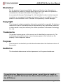
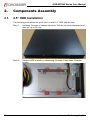
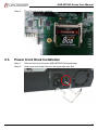
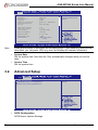
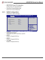
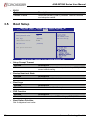
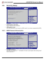
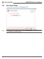
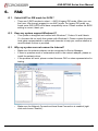
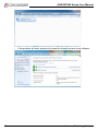
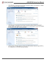
1
ANR-IB75N2 Series User Manual ANR-IB75N2 Series Networking Rackmount Server B75 PCH, 8x RJ45 GbE LAN (2-pair bypass), 0/2/4 SFP fiber GbE (w/o bypass) User Manual Acrosser Technology Co., Ltd. www.acrosser.com ANR-IB75N2 Series User Manual Disclaimer For the purpose of improving reliability, design and function, the information in this document is subject to change without prior notice and does not represent a commitment on the part of Acrosser Technology Co., Ltd. In no event will Acrosser Technology Co., Ltd. be liable for direct, indirect, special, incidental, or consequential damages arising out of the use or inability to use the product or documentation, even if advised of the possibility of such damages. Copyright This document contains proprietary information protected by copyright. All rights are reserved. No part of this manual may be reproduced by any mechanical, electronic, or other means in any form without prior written permission of Acrosser Technology Co., Ltd. Trademarks The product names appear in this manual are for identification purpose only. The trademarks and product names or brand names appear in this manual are the property of their respective owners. Purpose This document is intended to provide the information about the features and use of the product. Audience The intended audiences are technical personnel, not for general audiences. To read this User Manual on your smart phone, you will have to install an APP that can read PDF file format first. Please find the APP you prefer from the APP Market. 2 Acrosser Technology Co., Ltd. ANR-IB75N2 Series User Manual Table of Contents 1.Introduction....................................................................5 1.1. Specifications.............................................................................................................. 5 1.2. Package Contents....................................................................................................... 7 1.2.1. Model Type....................................................................................................... 7 1.2.2. Optional CPU List............................................................................................. 7 1.3. System Dissection....................................................................................................... 8 1.3.1.Dimension........................................................................................................ 8 1.3.2. Front Panel....................................................................................................... 9 1.3.3. Rear Panel..................................................................................................... 10 1.3.4. System Configuration......................................................................................11 2. Components Assembly.................................................12 2.1. 2.5” HDD Installation................................................................................................. 12 2.2. CF Card Installation................................................................................................... 16 2.3. Power Cord Hook Installation.................................................................................... 17 2.4. Rack Bracket Installation........................................................................................... 18 3. BIOS Settings................................................................19 3.1. Main Setup................................................................................................................ 19 3.2. Advanced Setup........................................................................................................ 20 3.2.1. SATA Configuration........................................................................................ 21 3.2.2. W83627DHG Super IO Configuration............................................................ 22 3.2.2.1. COM1 Configuration........................................................................ 22 3.2.2.2. COM2 Configuration........................................................................ 23 3.2.3. Serial Port Console Redirection..................................................................... 24 3.2.3.1. Console Redirection Settings.......................................................... 25 3.3. HW Monitor Setup..................................................................................................... 26 3.4. Chipset Setup............................................................................................................ 27 3.4.1. USB Configuration......................................................................................... 27 3.5. Boot Setup................................................................................................................. 28 3.6. Security Setup........................................................................................................... 29 3.6.1. HDD Password Description............................................................................ 29 3.7. Save & Exit Setup..................................................................................................... 30 4. Software Installation and Programming Guide............31 4.1.Introduction................................................................................................................ 31 4.1.1.GPIO.............................................................................................................. 31 www.acrosser.com 3 ANR-IB75N2 Series User Manual 4.1.1.1.Overview......................................................................................... 31 4.1.2.Watchdog....................................................................................................... 31 4.1.2.1.Overview......................................................................................... 31 4.1.3. LAN Bypass Subsystem................................................................................. 31 4.1.3.1.Overview......................................................................................... 31 4.1.4.LCD................................................................................................................ 31 4.1.4.1.Overview......................................................................................... 31 4.2. File Descriptions........................................................................................................ 32 4.2.1. GPIO/Watchdog/LAN Bypass Subsystem/LCM............................................. 32 4.3. API List and Descriptions.......................................................................................... 32 4.3.1.GPIO.............................................................................................................. 32 4.3.2.Watchdog....................................................................................................... 32 4.3.3. LAN Bypass Subsystem................................................................................. 33 4.3.4.LCM................................................................................................................ 34 4.3.4.1. Type Definitions............................................................................... 34 4.3.4.2. LCD Control Module........................................................................ 34 5. Driver and Utility Installation.......................................36 5.1. Driver CD Interface Introduction................................................................................ 36 5.2. Driver Installation Page............................................................................................. 38 5.3. Utility Installation Page.............................................................................................. 40 5.4. Application Installation Page..................................................................................... 42 5.5. Document Page......................................................................................................... 46 6.FAQ................................................................................47 Q 1. Select AHCI or IDE mode for SATA?......................................................................... 47 Q 2. Does my system support Windows 8?...................................................................... 47 Q 3. Why my system can not connect to Internet?........................................................... 47 Q 4. Where is the serial number located on my system?.................................................. 50 4 Acrosser Technology Co., Ltd. ANR-IB75N2 Series User Manual 1. Introduction The ANR-IB75N2 Series is designed for rack-mounted platform in networking appliance, e.g. VPN, SSL, UTM or firewall. With 3rd Generation Intel Core i7/i5/i3 Processors / Pentium CPU, and eight 10/100/1000Mbps LANs, ANR-IB75N2 Series is a powerful platform to satisfy various applications, sufficient for the small to middle size business security solution. 1.1. Specifications General CPU Support • • • • Chipset • Intel PCH B75 BIOS • Support console re-direction • Support bypass setting(default disable) • Support boot from LAN(RJ45 LAN1~LAN8) Memory • 2 x DIMM sockets support DDR3 1333/1600 up to 16GB 3rd Generation Inter Core i7 Processors i7-3770 3rd Generation Inter Core i5 Processors i5-3550S 3rd Generation Inter Core i3 Processors i3-3220 Intel Pentium Processor G2120 Network Interface Ethernet • • • • LAN by-Pass • LAN1/LAN2, LAN3/LAN4 support by-pass • Reserve 1 x 3-pin Jumper for hardware select bypass status GPIO • 8-bit GPIO (4-In, 4-Out) 8 x RJ45 0/2/4 x SFP Intel I210-AT (10/100/1000Mbps) (LAN1~LAN8) Intel 82576EB (10/100/1000Mbps) (F1~F4) Storage CF • 1 x Compact Flash Type II socket support UDMA HDD • 2 x 2.5” HDD bay SATA • 1 x SATA-2 port (SATA2) • 1 x SATA-3 port (SATA1) www.acrosser.com 5 ANR-IB75N2 Series User Manual Communication and I/O Front Panel Internal I/O • • • • • • • • LCM module Up, Down, Left, Right key pad Reset button Power LED/HDD/bypass 1 & 2: Green/Green/Yellow/ Yellow 0/2/4x SFP (F1~F4) COM port (RJ45) 2 x USB 3.0 LAN 8/7/6/5/4/3/2/1 • • • • • • 1 x 7-pin 2.54mm for LCM 1 x 8-pin 2.54mm for CPLD update 2 x 5-pin 2.00mm for VGA 2 x 5-pin 2.54mm for 8-bit GPIO (4-In, 4-Out) 1 x ATX 24-pin power input 1 x ATX12V 4-pin power input Others Watchdog Timer • Software programmable 0~255 Seconds, 0 = Disable Timer Battery • Lithium battery, 3V 220mAH (CR2032) Hardware Monitoring • CPU Voltage • CPU and System Temperature • CPU Fan Speed OS Support • • • • Fedora 14 (32/64 bit) Ubuntu 10.04 (32/64 bit) Windows 7 (32/64 bit) Windows 7 Embedded (32 bit) Mechanical Dimension • 440 x 317.5 x 44 mm Operating Temperature • 0 ~ 40°C (32 ~ 104°F) 6 Storage Temperature • -20 ~ 80°C (-4 ~ 176°F) Relative Humidity • 0 ~ 90% @ 40°C, non-condensing Power Supply • Standard ATX power (250W~300W) Acrosser Technology Co., Ltd. ANR-IB75N2 Series User Manual 1.2. Package Contents Check if the following items are included in the package. 1 x ANR-IB75N2, ANR-IB75N2A, or ANR-IB75N2B System 1 x Quick Manual 2 x SATA Cable 1 x Driver CD 1 x Console Cable (RJ45) 1 x Power Cord 2 x Rack Bracket 1 x Box Packing 14 x Screws for Bracket (for Rack + HDD bracket) 1 x Power Cord Hook 1.2.1. Model Type Model Description ANR-IB75N2 • 8 GbE LANs, 0 fiber LANs ANR-IB75N2A • 8 GbE LANs, 2 fiber LANs ANR-IB75N2B • 8 GbE LANs, 4 fiber LANs 1.2.2. Optional CPU List Model Description ANR-IB75N2/A/Bi71 • 3rd Generation Inter Core i7 Processors i7-3770 ANR-IB75N2/A/Bi51 • 3rd Generation Inter Core i5 Processors i5-3550S ANR-IB75N2/A/Bi31 • 3rd Generation Inter Core i3 Processors i3-3220 ANR-IB75N2/A/BPG1 • Intel Pentium Processor G2120 www.acrosser.com 7 ANR-IB75N2 Series User Manual 1.3. System Dissection 1.3.1. Dimension (Unit: mm) 8 Acrosser Technology Co., Ltd. ANR-IB75N2 Series User Manual 1.3.2. Front Panel Keypad LCM Module Fiber SFP LED1 RESET Console LED2 LAN 1~8 LED3 USB RJ45 LAN Connector LED LED1 LED2 Light Off Green Orange Yellow Blink Off Status 10Mbps 100Mbps 1000Mbps Link Link with Activity No Link LED1: SFP Status LED Display LED G Y G Y Light Green Yellow Green Yellow Status Link LED Active LED Link LED Active LED LED2: LAN Status LED Display LED G Y G Y Light Green Yellow Green Yellow Status Link LED Active LED Link LED Active LED LED3: Status/HDD/Power LED Display LED G G Y Y Light Green Green Yellow Yellow Status Power On LED HDD LED LAN3 & LAN4 Bypass LED LAN1 & LAN2 Bypass LED RESET: System Reset Button Push this button to reset the system. www.acrosser.com 9 ANR-IB75N2 Series User Manual 1.3.3. Rear Panel Power Inlet 10 Acrosser Technology Co., Ltd. ANR-IB75N2 Series User Manual 1.3.4. System Configuration Top Cover Power Supply Power Bracket CPU Heatsink Module HDD Bracket FAN Mainboard Bottom Base Membrane www.acrosser.com 1U Ear Bracket 11 ANR-IB75N2 Series User Manual 2. Components Assembly 2.1. 2.5” HDD Installation The following instructions will guide you to install 2.5” HDD step-by-step. 12 Step 1: Unfasten 2 screws of chassis top cover. Pull the top cover backward and then pull up to lift it up. Step 2: Release HDD bracket by unfastening 4 screws. Keep these 4 bracket screws. Acrosser Technology Co., Ltd. ANR-IB75N2 Series User Manual Step 3: Take out 4 HDD screws from the ANR-IB75N2 Series package. Step 4: Fasten your 2.5” HDD onto the HDD bracket by these 4 screws. www.acrosser.com 13 ANR-IB75N2 Series User Manual 14 Step 5: Fasten the HDD bracket onto the chassis by 4 bracket screws. Step 6: Plug 2 SATA cables to port [SATA1] or [SATA2] on mainboard. ([SATA1] is for SATA-3, [SATA2] is for SATA-2.) Acrosser Technology Co., Ltd. ANR-IB75N2 Series User Manual Step 7: The SATA cable MUST go under the power cables. Step 8: Firmly connect SATA signal cable and power cable to HDD module. www.acrosser.com 15 ANR-IB75N2 Series User Manual Step 9: 2.2. 16 Assemble top cover by fastening 2 screws. CF Card Installation Step 1: Open the top cover (same as previous steps). Step 2: Push your CF card into CF socket. Acrosser Technology Co., Ltd. ANR-IB75N2 Series User Manual Step 3: 2.3. The CF card is firmly installed. Power Cord Hook Installation Step 1: Take out the hook from the ANR-IB75N2 Series package. Step 2: Insert one end of the hook into the right-side hole first. www.acrosser.com 17 ANR-IB75N2 Series User Manual Step 3: 2.4. 18 Then insert the other end of the hook into the left-side hole. Rack Bracket Installation Step 1: Take out 6 screws and 2 rack brackets from the ANR-IB75N2 Series package. Step 2: Fix the rack brackets to chassis by fastening 6 screws. Acrosser Technology Co., Ltd. ANR-IB75N2 Series User Manual 3. BIOS Settings This chapter describes the BIOS menu displays and explains how to perform common tasks needed to get the system up and running. It also gives detailed explanation of the elements found in each of the BIOS menus. The following topics are covered: • Main Setup • Advanced Setup • HW Monitor • Chipset Setup • Boot Setup • Security Setup • Save Exit Setup 3.1. Main Setup Once you enter the AMI BIOS™ CMOS Setup Utility, the Main Menu will appear on the screen. Use the arrow keys to highlight the item and then use the <+> <-> keys to select the value you want in each item. Main Advanced HW Monitor Chipset Boot Security BIOS Information BIOS Vendor Core Version Compliancy Project Version Build Date and Time American Megatrends 4.6.5.3 UEFI 2.3; PI 1.2 IB75N2/A/B 07/25/2014 11:22:33 PCHI Information Intel PCH SKU Name B75 Save & Exit Set the Date. Use Tab to switch between Date elements. Processor Information Genuine Intel(R) CPU @ 2.40GHz Name IvyBridge Frequency 2400 MHz 306a5 Processor ID K0/M0 Stepping Number of Processors 2Core(s) / 4Thread(s) 7 Microcode Revision GT2 (900 MHz) GT Info www.acrosser.com 19 ANR-IB75N2 Series User Manual Main Note: Advanced HW Monitor Chipset Boot Security Name Frequency Processor ID Stepping Number of Processors Microcode Revision GT Info IvyBridge 2400 MHz 306a5 K0/M0 2Core(s) / 4Thread(s) 7 GT2 (900 MHz) IGFX VBIOS Version Memory RC Version Total Memory Memory Frequency 2137 1.7.0.0 8192 MB (DDR3) 1600 Mhz ME FW Version ME Firmware SKU System Date System Time 8.0.13.1502 1.5MB [Wed 01/01/2014] [11:22:33] Access Level Administrator Save & Exit Set the Time. Use Tab to switch between Time elements. Listed at the bottom of the menu are the control keys. If you need any help with the item fields, you can press <F1> key, and it will display the relevant information. • System Date Set the system date. Note that the ‘Day’ automatically changes when you set the date. • System Time Set the system time. 3.2. Advanced Setup Main Advanced HW Monitor Chipset SATA Configuration W83627DHG Super IO Configuration Serial Port Console Redirection Boot Security Save & Exit SATA Device Options Settings • SATA Configuration SATA Device Options Settings. 20 Acrosser Technology Co., Ltd. ANR-IB75N2 Series User Manual • W83627DHG Super IO Configuration System Super IO Chip Parameters. • Serial Port Console Redirection Serial Port Console Redirection. 3.2.1. SATA Configuration SATA Device Options Settings. Advanced SATA Mode Selection [AHCI] Serial ATA Software PORT 1 Serial ATA Software PORT2 CF CARD Software CF CARD Empty Unknown [Enabled] Empty Unknown [Enabled] Empty Unknown [Enabled] Port 1 Preserve Port 2 Preserve Preserve Determines how SATA controller(s) operate. • SATA Mode Selection Determines how SATA controller(s) operate. • PORT 1 Enable or Disable SATA Port. • PORT 2 Enable or Disable SATA Port. • CF CARD Enable or Disable SATA Port. www.acrosser.com 21 ANR-IB75N2 Series User Manual 3.2.2. W83627DHG Super IO Configuration System Super IO Chip Parameters. Advanced W83627DHG Super IO Configuration W83627DHG Super IO Ch COM1 Configuration COM2 Configuration W83627DHG Lan by Pass Function [Disabled] Set Parameters of Serial Port 1 (COMA) • COM1 Configuration Set Parameters of Serial Port 1 (COMA) • COM2 Configuration Set Parameters of Serial Port 2 (COMB) • LAN by Pass Function Enable or Disable LAN by pass function. 3.2.2.1. COM1 Configuration Advanced COM1 Configuration 22 Serial Port Device Settings [Enabled] IO=3F8h; IRQ=4; Change Settings [Auto] Select an optimal setting for Super IO device. Acrosser Technology Co., Ltd. ANR-IB75N2 Series User Manual • Change Settings Options Auto Description Select an optimal setting for Super IO device. IO=2F8h; IRQ=3; IO=3F8h; IRQ=3,4,5,6,7,10,11,12; IO=2F8h; IRQ=3,4,5,6,7,10,11,12; IO=3E8h; IRQ=3,4,5,6,7,10,11,12; IO=2E8h; IRQ=3,4,5,6,7,10,11,12; 3.2.2.2. COM2 Configuration Advanced COM2 Configuration Serial Port Device Settings [Enabled] IO=2F8h; IRQ=3; Change Settings [Auto] • Change Settings Options Auto Enable or Disable Serial Port (COM) Description Select an optimal setting for Super IO device. IO=2F8h; IRQ=3; IO=3F8h; IRQ=3,4,5,6,7,10,11,12; IO=2F8h; IRQ=3,4,5,6,7,10,11,12; IO=3E8h; IRQ=3,4,5,6,7,10,11,12; IO=2E8h; IRQ=3,4,5,6,7,10,11,12; www.acrosser.com 23 ANR-IB75N2 Series User Manual 3.2.3. Serial Port Console Redirection Serial Port Console Redirection. Advanced COM1 Console Redirection [Enabled] Console Redirection Settings Console Redirection Enable or Disable. Serial Port for Out-Of-Band Management/ Windows Emergency Management Services (EMS) EMS [Disabled] EMS Settings • Console Redirection Options Disabled / Enabled Description Console Redirection Enable or Disable. • Console Redirection Settings The settings specify how the host computer and the remote computer (which the user is using) will exchange data. Both computers should have the same or compatible settings. • EMS Options Disabled / Enabled Description Windows emergency management service • EMS Settings The settings specify how the host computer and the remote computer (which the user is using) will exchange data. Both computers should have the same or compatible settings. 24 Acrosser Technology Co., Ltd. ANR-IB75N2 Series User Manual 3.2.3.1. Console Redirection Settings Advanced COM1 Console Redirection Settings Terminal Type Bits per second Data Bits Parity Stop Bits Flow Control • Terminal Type Options VT100 / VT100+ / VT-UTF8 / ANSI • Bits per second Options 9600 / 19200 / 38400 / 57600 / 115200 • Data Bits Options 7/8 • Parity Options None / Even / Odd / Mark / Space • Stop Bits Options 1/2 www.acrosser.com [VT100+] [115200] [8] [None] [1] [None] Emulation: ANSI: Extended ASCII char set. VT100: ASCII char set. VT100+: Extends VT100 to support color, function keys, etc. VT-UTF8: Uses UTF8 encoding to map Unicode chars onto 1 or more. Description Emulation: ANSI: Extended ASCII char set. VT100: ASCII char set. VT100+: Extends VT100 to support color, function keys, etc. VTUTF8: Uses UTF8 encoding to map Unicode chars onto 1 or more. Description Selects serial port transmission speed. The speed must be matched on the other side. Long or noisy lines may require lower speeds. Description Data Bits Description A parity bit can be sent with the data bits to detect some transmission errors. Even: parity bit is 0 if the num of 1’s in the data bits is even. Odd: parity bit is 0 if num of 1’s in the data Description Stop bits indicate the end of a serial data packet. (A start bit indicates the standard setting is 1 stop bit. Communication with slow devices may require more than 1. 25 ANR-IB75N2 Series User Manual • Flow Control Options None / Hardware RTS/CTS 3.3. Description Flow control can prevent data loss from buffer overflow. When sending data, if the receiving buffers are full, a ‘stop’ signal can be sent to stop the data flow. HW Monitor Setup Main Advanced HW Monitor Chipset Boot Security Save & Exit PC Health Status SYS temperature CPU temperature CPU Fan Speed VCORE : : : : +29°C +36°C 1030 RPM +1.000 V • SYS temperature This item displays the System temperature • CPU temperature This item displays the CPU temperature • CPU Fan Speed This item displays the CPU fan speed • VCORE This item displays the VCORE voltage. 26 Acrosser Technology Co., Ltd. ANR-IB75N2 Series User Manual 3.4. Chipset Setup Main Lan Lan Lan Lan Lan Lan Lan Lan Advanced HW Monitor 1 2 3 4 5 6 7 8 Chipset Boot Security [Enabled] [Enabled] [Enabled] [Enabled] [Enabled] [Enabled] [Enabled] [Enabled] Save & Exit Control the Lan Port Enable / Disable. USB Configuration • Lan 1 ~ Lan 8 Options Disabled / Enabled Description Control the LAN Port Enable / Disable. 3.4.1. USB Configuration Main Advanced HW Monitor Chipset Boot USB Configuration xHCI Mode [Smart Auto] EHCI1 [Enabled] • xHCI Mode Options Smart Auto / Auto / Disabled / Enabled www.acrosser.com Security Save & Exit Mode of operation of xHCI controller. Description Mode of operation of xHCI controller. 27 ANR-IB75N2 Series User Manual • EHCI1 Options Disabled / Enabled 3.5. Description Control the USB EHCI (USB 2.0) functions. One EHCI controller must always be enabled. Boot Setup Main Advanced HW Monitor Chipset Boot Configuration Setup Prompt Timeout Bootup Numlock State 1 [On] Boot Logo [Enabled] CSM16 Module Version 07.69 PXE Function [Disabled] Boot Security Save & Exit Number of seconds to wait for setup activation key. 65535(0xFFFF) means indefinite waiting. Boot Option Priorities • Setup Prompt Timeout Options N/A Description Number of seconds to wait for setup activation key. 65535(0xFFFF) means indefinite waiting. • Bootup NumLock State Options On / Off Description Select the keyboard NumLock state • Boot Logo Options Disabled / Enabled Description Enables or disables Quiet Boot option • PXE Function Options Disabled / Enabled Description Controls the execution of UEFI and Legacy PXE OpROM • Boot Option Priorities Set th esystem boot order. 28 Acrosser Technology Co., Ltd. ANR-IB75N2 Series User Manual 3.6. Security Setup Main Advanced HW Monitor Chipset Boot Security Password Description Save & Exit Set Administrator Password If the Administrator’s password is set, then this only limits access to Setup and is only asked for when entering Setup. The password length must be in the following range: Minimum length 3 Maximum length 20 Administrator Password HDD Security Configur HDD0:ST750LX003-1 • Administrator Password Set the administrator password • HDD module name Set HDD password (It will show the HDD model, if you have connected the HDD.) 3.6.1. HDD Password Description Main Advanced HW Monitor Chipset Boot HDD Password Description : Allows Access to Set, Modify and Clear HardDisk User and Master Passwords. User Password need to be installed for Enabling Security. Master Password can be Modified only when successfully unlocked with Master Password in POST. Security Save & Exit Set HDD User Password. *** Advisable to Power Cycle System after Setting Hard Disk Passwords *** HDD PASSWORD CONFIGURATION: Security Supported Security Enabled Security Locked Security Frozen HDD User Pwd Status HDD Master Pwd Status Yes No No No NOT INSTALLED Installed Set User Password • Set HDD Password Set HDD User Password. *** Advisable to Power Cycle System after setting Hard Disk Passwords *** www.acrosser.com 29 ANR-IB75N2 Series User Manual 3.7. Save & Exit Setup Main Advanced HW Monitor Chipset Boot Security Save Changes and Exit Discard Changes and Exit Save & Exit Exit system setup after saving the changes. Save Options Save Changes Discard Changes Restore Defaults Save as User Defaults Restore User Defaults Boot Override • Save Changes and Exit Exit system setup after saving the changes. • Discard Changes and Exit Exit system setup without saving any changes. • Save Changes Save Changes done so far to any of the setup options. • Discard Changes Discard Changes done so far to any of the setup options. • Restore Defaults Restore/Load Default values for all the setup options. • Save as User Defaults Save the changes done so far as User Defaults. • Restore User Defaults Restore the User Defaults to all the setup options. 30 Acrosser Technology Co., Ltd. ANR-IB75N2 Series User Manual 4. Software Installation and Programming Guide 4.1. Introduction 4.1.1. GPIO 4.1.1.1. Overview ANR-IB75N2 Series provides GPIO interface.Users can use the GPIO APIs to Control GPO Pin. 4.1.2. Watchdog 4.1.2.1. Overview ANR-IB75N2 Series provides a Watchdog timer. Users can use the Watchdog APIs to configure and to access the Watchdog timer. The Watchdog timer can be set to 1~255 seconds. Setting the timer to zero disables the timer. The remaining seconds of the timer to reboot can be read from the timer. 4.1.3. LAN Bypass Subsystem 4.1.3.1. Overview Two pairs of LAN ports on ANR-IB75N2 Series implement the bypass function. Users can invoke the LAN Bypass APIs to control the bypass states of the LAN ports. 4.1.4. LCD 4.1.4.1. Overview The LCM (short for LCD Control Module) APIs provide interfaces to control the module. By invoking these APIs, programmers can implement the applications which have the functions listed below: 1. Clear LCD screen. 2. Turn on or off the cursor on the screen. 3. Move the cursor on the screen. 4. Turn on or off the text on the screen. 5. Get the identification of the pressed key of the LCM. 6. Show the text on the screen. www.acrosser.com 31 ANR-IB75N2 Series User Manual 4.2. File Descriptions 4.2.1. GPIO/Watchdog/LAN Bypass Subsystem/LCM 1. Libw83627.h This file includes the declarations of the APIs and macro definitions. 2. Makefile 4.3. API List and Descriptions 4.3.1. GPIO Syntax: Get_gpi_status(int pin) Description: Get the status of GPIO input pins and output pins status. Parameters: This function takes a pointer to an unsigned char variable as the parameter. The pin0 ~ pin3 is the status of the input pins. Return Value: 1:HIGH, 0:LOW. Syntax: Get_gpo_status(int pin) Description: Get the status of GPIO output pins status. Parameters: This function takes a pointer to an unsigned char variable as the parameter. The pin0 ~ 3 is the status of the output pins. Return Value: 1:HIGH, 0:LOW Syntax: Set_gpo(int pin, int value) Description: Set the status of GPIO Output value. Parameters: Set value 0 is Low, 1 is High. Return Value: If the function sets the values successfully, it returns 0 or -1, any other returned value stands for error. 4.3.2. Watchdog 32 Syntax: Void wdt_start(int _timevalue) Description: This function read the value of the watchdog time counter. Parameters: The parameter ‘val’ is the value to set to watchdog timer register. The range is 1 ~ 255. Acrosser Technology Co., Ltd. ANR-IB75N2 Series User Manual Return Value: This function return the value of the time counter and return it to the caller as an unsigned integer. Syntax: Int get_wdt_count(void) Description: This function get the watchdog timer register to the value ‘val’ and starts to count down. Parameters: None. Return Value: This function returns the value of the time counter. Syntax: Void wdt_stop(void) Description: This function sets the watchdog timer stop Parameters: None. Return Value: None. 4.3.3. LAN Bypass Subsystem 1. void enableWtd(void) Enable Watchdog Timer. (This timer is different from the System Watchdog timer). 2. void disableWtd(void) Disable Watchdog Timer. 3. void reloadWtd(void) Reload Watchdog Timer. 4. void forceNormal(void) Force the port to become normal state. 5. void forceBypass(void) Force the port to become bypass state. 6. void setWtd4(void) Set the watchdog timer to 4 seconds. 7. void setWtd8(void) Set the watchdog timer to 8 seconds. 8. void setWtd16(void) Set the watchdog timer to 16 seconds. 9. void setWdt32(void) Set the watchdog timer to 32 seconds. www.acrosser.com 33 ANR-IB75N2 Series User Manual 4.3.4. LCM 4.3.4.1. Type Definitions Typedefchar i8; Typedef u8; unsigned char Typedefshort i16; Typedef unsigned short u16; Typedef unsigned long u32; Typedefint i32; 4.3.4.2. LCD Control Module 1. i32 clrscrLcm( void ) Description: Clear the screen of the LCM. Return value: 0 after the screen is cleared. 2. i32 cursorLcm( bool mode ) Description: According to the argument ‘mode’, show the cursor on the LCM screen or eliminate the cursor on the LCM screen. The position of the cursor is unchanged. mode = true, show the cursor. mode = false, eliminate the cursor. Return value: 0 after the cursor has been shown or eliminated. 3. i32 cursorActionLcm( i32 type) Description: According to the argument ‘type’, move the cursor to the indicated position. The displayed text is not altered. type = HOME, move the cursor to row 0, column 0. type = MOVERIGHT, move the cursor to the column which is to the right of its original position if the original column < 15. type = MOVELEFT, move the cursor to the column which is to the left of its original position if the original column > 0. type = MOVEBACK, move the cursor to the column which is to the left of its original position and delete the character at the new position if the original column > 0. Return value: 0 after the cursor is moved. 4. i32 displayLcm( bool mode ) Description: Show the text on the LCM screen or eliminate the text on the LCM screen. The content of the text is not altered. 34 Acrosser Technology Co., Ltd. ANR-IB75N2 Series User Manual mode = true, show the text. mode = false, eliminate the text. Return value: 0 after the text has been shown or eliminated. 5. i32 getKeyLcm( void ) Description: Scan the LCM and return the identification of the pressed direction key. Return value: ‘UP’ if the ‘up’ direction key is pressed. ‘RIGHT’ if the ‘right’ direction key is pressed. ‘LEFT’ if the ‘left’ direction key is pressed. ‘DOWN’ if the ‘down’ direction key is pressed. ‘NONE’ if none of the keys is pressed. 6. i32 getPositionLcm( i32 *row, i32 *column ) Description: Get the position of the cursor and write the coordinate to the memory pointed at by arguments ‘row’ and ‘column’. Return value: 0 if the request for the coordinate has been served. 7. i32 setPositionLcm( i32 row, i32 column ) Description: Set the position of the cursor according to the arguments ‘row’ and ‘column’. Return value: 0 after the position has been set. -1 if the argument ‘row’ or ‘column’ meets any of the following conditions: (1) row is not 0. (2) row is not 1. (3) column is less than 0. (4) column is greater than 15. 8. i32 showLcm( i32 length, u8 *info ) Description: Start from the current position of the cursor; print the text pointed at by ‘info’ to the LCM screen. The number of characters to be printed is at most ‘length’. If the remaining columns available for printing the text is less than ‘length’, the number of the characters to be printed is: 16 – ( column number of the current position of the cursor ). Return value: 0 after the text is printed. www.acrosser.com 35 ANR-IB75N2 Series User Manual 5. Driver and Utility Installation 5.1. Driver CD Interface Introduction Acrosser provides a Driver CD compiled with all the drivers, utilities, applications and documents this product may need. For Windows environment, it can be guided by the setup program automatically. For Linux environment, the related files can be found at folder “IB75N2\Linux”. Put the Driver CD into your CD-ROM drive. The Driver CD will automatically detect the mainboard information to see if they are matched. The following error messages appear if you use an incorrect Driver CD version with your mainboard. Please find the correct Driver CD to proceed. 36 Acrosser Technology Co., Ltd. ANR-IB75N2 Series User Manual Put the correct Driver CD of your mainboard into your CD-ROM drive. The following installation screen should appear. If not, enter the root folder of the Driver CD, run the excution file “Setup.exe“. www.acrosser.com 37 ANR-IB75N2 Series User Manual 5.2. Driver Installation Page Step 1: Select the “Driver” tab. Click the “Select All” button to select all the driver checkboxes, and then click “Install” button to start installing all the selected drivers. Note: Select the “Clear All“ button will clear all the selections, and then you can select the driver you want to install one by one, but the “Chipset” driver has to be installed before installing all the others. 38 Acrosser Technology Co., Ltd. ANR-IB75N2 Series User Manual Step 2: The driver installation started. Step 3: The driver installation finished. The configuration will be valid after reboot. www.acrosser.com 39 ANR-IB75N2 Series User Manual 5.3. Utility Installation Page Step 1: Select the “Utility” tab. Click the “Test Utility” box. Step 2: The “Test Utility” screen appears. 40 Acrosser Technology Co., Ltd. ANR-IB75N2 Series User Manual Select (1) GPIO TEST: Select (2) Watchdog TEST: Select (3) LanbyPass TEST: www.acrosser.com 41 ANR-IB75N2 Series User Manual Select (4) LCM TEST: 5.4. Application Installation Page Step 1: Select the “Application” tab. Click the “Acrobat Reader XI” box. Note: The “Acrobat Reader” is necessary for reading the user manual in PDF file format. 42 Acrosser Technology Co., Ltd. ANR-IB75N2 Series User Manual Step 2: Install “Intel_MEI” components driver. www.acrosser.com 43 ANR-IB75N2 Series User Manual Step 3: 44 Install “Acrosser Driver” into the system. Windows OS will create “AcroDev” device. Acrosser Technology Co., Ltd. ANR-IB75N2 Series User Manual If the “Windows Security” warning message appears, select “Install this driver software anyway” to go on next step. For Windows 64-bit OS, enter the cmd.exe command, type “bcdedit /set testsigning on” to enter the Windows test mode. Reboot the system after executed this command. www.acrosser.com 45 ANR-IB75N2 Series User Manual 5.5. Document Page The user manual is stored in the “Document” folder. Note: 46 To read the PDF file, you will have to install “Acrobat Reader” first. Please refer to the “Application Installation Page”. Acrosser Technology Co., Ltd. ANR-IB75N2 Series User Manual 6. FAQ Q 1. Select AHCI or IDE mode for SATA? • There are 2 SATA modes to select --- AHCI & legacy IDE mode. When you use the Linux, We strongly suggest to use AHCI mode. For legacy IDE mode, we found some SATA HDD could have compatibility issue. Please confirm the BIOS setting is correct, thank you. Q 2. Does my system support Windows 8? • This system is designed and verified with Windows 7, Fedora 14 and Ubuntu 10. Acrosser did not verify this system with Windows 8. Please contact Acrosser local sales representative or authorized channels to help you confirm whether a new Windows 8 driver is provided. Q 3. Why my system can not connect to Internet? • Make sure the network adapter can be recognized in Device Manager. • If there is question mark or exclamation mark in the network adapter, please reinstall the network driver. • If the problem still exist, please contact Acrosser FAE or sales representative for testing. • Make sure the Network Connections/Local Area Connection is enabled (right click and choose “Enable”). www.acrosser.com 47 ANR-IB75N2 Series User Manual • If the problem still exist, please shut down the firewall and anti-virus software. 48 Acrosser Technology Co., Ltd. ANR-IB75N2 Series User Manual • If the Network Connections/Local Area Connection show “no connection”, please check your network cable connection. • If the Network Connections/Local Area Connection show “limited connection”, please disable and enable your connection to fix this problem. Or, you can unplug and plug the LAN cable to fix the problem. • If the problem still exist, please contact your MIS whether there are any DHCP or IP configuration or ISP/WAN setting limitation. www.acrosser.com 49 ANR-IB75N2 Series User Manual Q 4. Where is the serial number located on my system? • The serial number (S/N) is an alpha-numeric character located on the bottom or side chassis. (for reference only) 50 Acrosser Technology Co., Ltd. ANR-IB75N2 Series User Manual Technical Support Form We deeply appreciate your purchase of Acrosser products. Please find the “tech_form. doc” file in our utility CD. If you have any questions or problems about Acrosser products, please fill in the following information. We will answer your questions in the shortest time possible. Describe Your Info and Acrosser System Info • Your Company Name: • Your Contact Info: Phone Number: • Your E-Mail Address: • Your Company Address: • Acrosser Model Name: • Acrosser Serial Number: Describe System Configuration • CPU Type: • Memory Size: • Storage Device (e.g. HDD, CF, or SSD): • Additional Peripherals (e.g. Graphic Card): • Operating System & Version (e.g. Windows 7 Embedded): • Special API or Driver: (If yes, please provide it for debug.) • Running Applications: • Others: Describe Your Problems or Questions: Send the above information to one of the following Acrosser contacts: • • • • Acrosser Local Sales Representative Acrosser Authorized Sales Channels Acrosser Inquiry --- http://www.acrosser.com/inquiry.html Acrosser FAX Number --- 886-2-29992887 www.acrosser.com 51 Acrosser Headquarters 241新北市三重區光復路一段61巷26號10樓 10F., No.26, Ln. 61, Sec. 1, Guangfu Rd., Sanchong Dist., New Taipei City 241, Taiwan, R.O.C. TEL: +886-2-29999000 FAX: +886-2-29992887 Acrosser Taichung Office 408台中市南屯區河南路四段162號12樓之6 12F.-6, No.162, Sec. 4, Henan Rd., Nantun Dist., Taichung City 408, Taiwan, R.O.C. TEL: +886-4-22510659 FAX: +886-4-22546079 Acrosser China Subsidiary 深圳市欣扬通电子有限公司 深圳市福田区车公庙泰然九路21号 皇冠科技园3栋2楼 (邮编: 518040) 2F., 3rd Building, Crown Science Park, No. 21, Tai-Ran 9th Rd., Che Gong Miao, Futian Dist., Shenzhen, China (Postal:518040) TEL: +86-755-83542210 FAX :+86-755-83700087 Acrosser Shanghai Office 欣扬通电子有限公司 上海分公司 上海市徐汇区零陵路631号爱乐大厦12E (邮编: 200085) 12E, Aile Building, No.631, Ling-ling Road, Xu-Hui Dist., Shanghai, China (Postal:200085) TEL: +86-21-64288853 FAX: +86-21-64288854 Acrosser Beijing Office 欣扬通电子有限公司 北京分公司 北京市海淀区安宁庄西三条9号 宜品上层2-703 (邮编: 100085) Room 2-703, Yipinshangceng, No.9, Xisantiao, Anning Zhuang, Haidian Dist., Beijing, China (Postal:100085) TEL: +86-10-82359009 FAX: +86-10-82359003 Acrosser USA Inc. 11235 Knott Ave. Suite A, Cypress, CA 90630, USA Toll Free: +1-866-401-9463 TEL: +1-714-903-1760 FAX: +1-714-903-5629