1
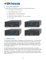
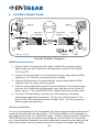
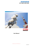
User Guide
HDMI™ Fiber Optic Extender
DVI-7360
TABLE OF CONTENTS
SECTIONPAGE
PRODUCT SAFETY . . . . . . . . . . . . . . . . . . . . . . . . . . . . . . . . . . . . 1
PRODUCT LIABILITY. . . . . . . . . . . . . . . . . . . . . . . . . . . . . . . . . . . 1
1.INTRODUCTION. . . . . . . . . . . . . . . . . . . . . . . . . . . . . . . . . . . 2
2.SPECIFICATIONS. . . . . . . . . . . . . . . . . . . . . . . . . . . . . . . . . . 3
3. PACKAGE CONTENTS. . . . . . . . . . . . . . . . . . . . . . . . . . . . . . 4
4.INSTALLATION. . . . . . . . . . . . . . . . . . . . . . . . . . . . . . . . . . . . 4
5. SYSTEM CONNECTIONS. . . . . . . . . . . . . . . . . . . . . . . . . . . . 5
6.TROUBLESHOOTING. . . . . . . . . . . . . . . . . . . . . . . . . . . . . . . 6
7. LIMITED WARRANTY. . . . . . . . . . . . . . . . . . . . . . . . . . . . . . . 7
8. REGULATORY COMPLIANCE. . . . . . . . . . . . . . . . . . . . . . . . 7
WARNING – Product Safety
1. Do not dismantle the product housing or modify the printed circuit board
module as this may result in electrical shock or burn.
2. Do not attempt to service this product yourself as opening or removing the
product housing may expose you to dangerous voltages or other hazards.
Refer all servicing to qualified service personnel.
3. Keep this product away from liquids. Spills into the product housing may
result in fire, electrical shock, or equipment damage. If liquid spills into the
housing, unplug the product immediately. Have the product checked by a
qualified service engineer before using it again.
4. Place the product in an even and stable location. If the product falls or is
dropped, it may cause an injury and/or malfunction.
5. Avoid exposing the product to extreme temperatures or to high humidity
levels as this may result in damage to the product.
6. Only use the supplied External AC Power Adapter. The use of other power
adapters may cause this product to fail or may cause a fire.
7. Do not twist or exert excessive force on the ends of the optical cable as this
can cause it to malfunction. Take precaution to ensure that the fiber optic
cable is not forced to bend tighter than its minimum bend radius.
Product Liability
Every effort has been made to ensure that this product is free of defects.
DVIGear cannot be held liable for the use of this product or for any direct or
indirect consequential damages arising from its use. It is the responsibility of
the users of this product to check that it is suitable for their requirements and
that it is installed correctly.
All rights are reserved. No parts of this manual may be reproduced or transmitted
by any form or means electronic or mechanical, including photocopying,
recording or by any information storage or retrieval system without the written
consent of DVIGear.
DVIGear reserves the right to revise any of its hardware and software following
its policy to modify and/or improve its products where necessary or desirable.
This statement does not affect the legal rights of the user in any way. All
third-party trademarks and copyrights are recognized. The DVIGear logo is a
registered trademark of DVIGear, Inc. HDMI™ is a registered trademark of
HDMI LLC. All other trademarks are the property of their respective holders.
-1-
1.INTRODUCTION
The DVI-7360 HDMI™ Fiber Optic Extender enables the transmission of very
high-speed (10.2 Gbps.) HDMI and single-link DVI signals over distances up
to 4500 meters (2.8 miles) without any signal degradation. This makes it an
ideal solution for applications where HDMI or DVI signals must be routed long
distances from the source without introducing artifacts in the image.
Our professional digital distribution products have been serving the industry
for over ten (10) years. DVIGear offers a full line of high-quality Digital Matrix
Routers, Switchers, Splitters, Video Scalers, Up/Down/Cross Converters,
Format Converters, Analog-Digital Converters, as well as a wide range of
long-reach Digital Cables, Extenders, and Optical Transmission systems.
Features
This product offers several unique features and benefits:
• Long distance transport of high-speed single-link DVI or HDMI signals
using either single-mode or multi-mode fiber optic cables.
• Uses detachable 2-strand fiber optic cables that can easily be pulled
through 1/2” conduit and can be terminated in the field.
• No copper cables are required. EDID and HDCP communications are
supported through the fiber optic connection.
• Cable distances up to 4.5 kilometers can be achieved with single-mode
fiber. Up to 500 meters can be achieved with multi-mode fiber. With
HDCP encrypted signals, the maximum cable length is 350 meters.
• Supports HDTV resolutions up to 1080p/60 with 16-bit color and PC
resolutions up to 4096 x 2160 (p24).
• Supports HDMI bit rates up to 3.4 Gbps/color (10.2 Gbps. total).
• Immune to environmental signal noise.
• Low RFI/EMI emissions for sensitive applications.
• Includes +5VDC External AC Power Adapters for both Transmitter and
Receiver units.
-2-
2.SPECIFICATIONS
General Specifications
Maximum Pixel Clock Rates
up to 340 MHz
Maximum Bit-Rates
up to 3.4 Gbps per color, 10.2 Gbps total
Maximum Supported
Resolutions
PC: HDTV: up to 4096 x 2160 (p24)
up to 1080p / 60 with 16 bit color
Connector Types
HDMI I/O Ports: Optical I/O Ports:
Power Supply:
IR Transmitter:
IR Receiver:
HDMI female 19-pin connector
2x LC connectors
5.5 mm locking mini-jack
3.5 mm mono mini-jack
3.5 mm stereo mini-jack
Maximum Cable Length
9μ /125μ Single-Mode Fiber : 4,500 meters, 2.8 miles
50μ /125μ Multi-Mode Fiber : 500 meters, 1,640 ft.
SM or MM fiber with HDCP: 350 meters, 1,150 ft.
Optical Specifications
Optical Transmitter
Laser Source: 1310nm FP / 1430nm FP / 1550nm FP
Optical Receiver
PIN Photo Diode O/E Converter
Suggested Fiber Optic Cable
50/125 µ Multi-Mode or 9/125 µ Single-Mode fiber, 2x LC connectors
Power
Power Source
Both Tx and Rx units must use the included AC power adapters.
External AC Power Adapters
Input: 100-240 VAC / 50-60 Hz, 0.5A Output: +5 VDC, 3.0 A
Power Consumption
DVI-7360-Tx: 3.5 watts
DVI-7360-Rx: 3.5 watts
Mechanical
Dimensions (L x W x H)
4.61” x 2.95” x 1.16”
Net Weight (RX and TX each)
6.1 oz. (172 g)
Shipping Weight
2.4 lb. (1.1 kg)
Construction
Extruded Aluminum enclosure with black anodized finish
(117.2 mm x 75 mm x 29.5 mm)
Environmental Specifications
Operating Temperature Range
32° to 122° F ( 0° to 50° C)
Storage Temperature Range
-4° to 158° F (-20° to 70° C)
Relative Humidity
10% - 90% non-condensing
Model Number
DVI-7360
HDMITM Fiber Optic Extender
Regulatory Compliance
Extenders
FCC Class B, CE, RoHS
Power Adapters
UL, CUL, GS, PSE, CE, FCC, RCM, RoHS
Conformance
DVI v1.0, HDMI v1.3, HDCP v1.4
-3-
3. PACKAGE CONTENTS
Before starting installation, please check the package contents:
• 1x DVI-7360-Tx Transmitter Unit
• 1x DVI-7360-Rx Receiver Unit
• 1x IR Transmitter (p.n. DVI-7360-IR-TX)
• 1x IR Receiver (p.n. DVI-7360-IR-RX)
• 2x External AC Power Adapters (p.n. DVI-7205-PS)
• 1x User Guide
4.INSTALLATION
This product includes both a Transmitter and a Receiver unit. The Transmitter
unit should be connected to the HDMI output port of the signal source (such
as a PC or BluRay player). The Receiver should be connected to the HDMI
input port of a digital display. This product may be connected to a DVI source
and/or display using a DVI to HDMI cable (DVIGear p.n. DVI-24xx-HR, where
xx = length in meters).
The HDMI signal components are routed from the Transmitter unit to the
Receiver unit using an optical cable with two (2) fibers that are terminated with
LC optical connectors. The optical cable may use either single-mode or multimode fiber. The longest cable distances may be obtained with single-mode
fiber. Systems that require HDCP support are limited to cable distance of 350
meters (1,150 ft.).
-4-
5. SYSTEM CONNECTIONS
HDMI Port
HDMI Cable*
IR Tx
LC2
LC1
LC1
LC2
DVI-7360-TX
Transmitter
HDMI Port
DVI-7360-RX
Receiver
HDMI Fiber Optic Transmitter
HDMI Cable*
HDMI Fiber Optic Receiver
IR Signal Path
DVI-7360-Tx
DVI-7360-Rx
AC Power
Adapter
AC Power
Adapter
IR Remote
IR Rx
*HDMI cables not supplied
Typical System Diagram
HDMI Interconnections
1. Connect each strand of the fiber optic cable to the corresponding
optical ports on the Transmitter and Receiver units that are marked
LC1 and LC2.
2. Connect the Transmitter unit to the source using a high-quality HDMI
cable (e.g., PC, Blu-Ray, receiver/switcher output).
3. Connect the Receiver unit to the display using a high-quality HDMI
cable (or receiver input, switcher input).
4. Connect the supplied External AC Power Adapters to the power input
jacks on the Transmitter and Receiver units and then to an active AC
power source. The red POWER LEDs should illuminate on both units.
5. First turn ON the Display, and then turn ON switchers and other
distribution equipment (if present). Finally, turn ON the source. The
green LINK LEDs should illuminate on both units. Test the system to
ensure proper performance.
IR Interconnections
This unit is equipped with an IR repeater port that supports remote extension of
certain IR devices over the optical link. The IR information is sent upstream in
the opposite direction w.r.t. the HDMI signal. Connect the IR receiver to the DVI7360-RX Receiver unit and the IR transmitter to the DVI-7360-TX Transmitter
unit. Note that the IR receiver must be visible to the remote control device and
the IR transmitter must be visible to the source device for proper operation.
-5-
6.TROUBLESHOOTING
If the system fails to display a signal, power OFF all devices and check that the
following connections are properly installed:
•
The DVI-7360-TX Transmitter unit must be connected to the Source. The
DVI-7360-RX Receiver unit must be connected to the Display.
•
Both the Transmitter unit and the Receiver unit must be connected to
the included external AC power adapters, which must be connected to a
working AC power source. Confirm that the red Power LEDs on both units
are illuminated, indicating that there is power to both devices.
•
Both strands of the fiber optic cable must be routed to the LC optical port
with the corresponding number on both the Transmitter and Receiver units.
For example, Fiber Strand #1 must be connected to Optical Port LC1 on
both the Transmitter and Receiver units. This applies to strand 2 as well.
Once all connections have been verified, power ON the monitor first, then any
intermediate equipment such as switchers, and finally the HDMI signal source.
The green LINK LEDs should illuminate on both units.
If the system still fails to display an image, check to ensure that the HDMI signal
source is compatible with the display by making a direct connection between the
two so as to bypass the DVI-7360 HDMI Fiber Optic Extender. If there is still no
image, then there is a compatibility issue between the source and the display that
must be resolved.
After trying the above suggestions, should the problem still persist, contact your
dealer for additional suggestions. Should the dealer’s technical personnel be
unable to assist you, please contact DVIGear via telephone at 1.888.463.9927
(United States and Canada); international callers may dial 1.770.421.6699 or
send an e-mail to [email protected].
-6-
7. LIMITED WARRANTY
LIMITED WARRANTY – With the exceptions noted in the next paragraph,
DVIGear, Inc. warrants the original purchaser that the equipment it manufactures
or sells will be free from defects in materials and workmanship for a period of
three years from the date of purchase. Should this product, in DVIGear’s
opinion, prove defective within this warranty period, DVIGear, at its option, will
repair or replace this product without charge. Any defective parts replaced
become the property of DVIGear. This warranty does not apply to those
products which have been damaged due to accident, unauthorized alterations,
improper repair, modifications, inadequate maintenance and care, or use in any
manner for which the product was not originally intended.
If repairs are necessary under this warranty policy, the original purchaser must
obtain a Return Authorization Number from DVIGear and return the product,
freight prepaid, to a location designated by DVIGear. After repairs are complete,
the product will be returned, freight prepaid.
LIMITATIONS – All products sold are “as is” and the above Limited Warranty is
in lieu of all other warranties for this product, expressed or implied, and is strictly
limited to three (3) years from the date of purchase. DVIGear assumes no liability
to distributors, resellers, end-users, or any third parties for any loss of use,
revenue, or profit.
DVIGear makes no other representation of warranty as to fitness for the purpose
or merchantability or otherwise in respect of any of the products sold. The liability
of DVIGear with respect to any defective products will be limited to the repair
or replacement of such products. In no event shall DVIGear be responsible or
liable for any damage arising from the use of such defective products whether
such damages are direct, indirect, consequential or otherwise, and whether such
damages are incurred by the reseller, end-user, or any third party.
8. REGULATORY COMPLIANCE
This product has been tested and found to be in compliance with applicable
FCC and CE rules and regulations. The External AC Power Adapter is compliant
with UL, CUL, CE, PSE, and GS regulations. These products are RoHS
compliant.
-7-
Your Digital Connectivity Experts
Toll Free 888.463.9927
Phone
770.421.6699
Fax
770.234.4207
DVIGear, Inc.
1059 Triad Court, Suite 8
Marietta, Georgia 30062-2258
www.dvigear.com
DVI-7360-UG-01 / Feb.2012