1
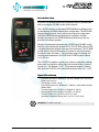
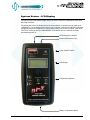
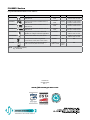
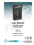
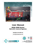
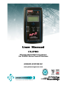
User Manual
CS-IPRO
Wireless Hand-Held Programmer
for CS-DMX Series Control Stations
JOHNSON SYSTEMS INC.
www.johnsonsystems.com
Table of Contents
Warranty...........................................................................................................2
User Manual Copies.........................................................................................2
Introduction.......................................................................................................3
Specifications...................................................................................................3
Battery Replacement........................................................................................4
Security............................................................................................................4
User Interface...................................................................................................4
System Status - LCD Display...........................................................................5
Quick Programming Reference to System Configuration Menu Items.................... 6
Detailed Programming of System Configuration Menu Items................................... 7
Typical Application Procedures......................................................................11
Warranty
The CS-IPRO comes with a standard one (1) year warranty against defects
in parts and workmanship.
User Manual Copies
Additional copies of the most recent version of this manual can be
downloaded at:
http://www.johnsonsystems.com/cs_ipro_user_manual.htm.
2
www.johnsonsystems.com
Introduction
CS-IPRO is a wireless hand-held programmer used to communicate
with and configure CS-DMX series control stations.
The CS-IPRO features a removable EEPROM Memory Module used
to save/backup the DMX channel patch configuration. The EEPROM
Memory Module can be easily removed and stored in a safe place.
Additional EEPROM Memory Modules are available if multiple
backups are required. An EEPROM Memory Module may also be
provided for firmware updates.
Wireless communication between the CS-IPRO and CS-DMX control
stations is via bidirectional infrared LED’s. The CS-IPRO infrared LED
is located behind the window at the top of the enclosure. The CS-DMX
control station infrared LED window is located on the front, between
the master slider and slider 1. The maximum range for sending and
receiving data between the CS-IPRO and CS-DMX control stations
is 12” (30 cm).
CS-IPRO
The CS-IPRO is capable of printing out various configuration settings
when used in conjunction with a hand-held infrared printer (Johnson
System Inc., Part Number: JS-IP). The maximum range for sending
data from the CS-IPRO to the hand-held infrared printer is 6' (1.8 m).
Specifications
• Enclosure Dimensions: Width 2.75" (70 mm) x Height 4.95" (125 mm) x
Depth 0.95" (24 mm)
• Total Weight: 0.33 lb. (150 g)
• Power Requirement: 2 x AA Batteries - Alkaline or Nickel Metal Hydride
(NiMh) ONLY!
• Transmit Range from CS-IPRO to CS-DMX: 12" (30cm)
• Receive Range from CS-DMX to CS-IPRO: 12" (30cm)
• Transmit Range from CS-IPRO to JS-IP: 6' (1.8m)
• Operating Temperature Range: 50°F (10°C) to 104°F (40°C)
WARNING: For indoor use only!
www.johnsonsystems.com
3
Battery Replacement
2 x AA Batteries
Alkaline or Nickel Metal Hydride (NiMh) ONLY!
Ensure batteries are installed as indicated inside the battery compartment.
The combined voltage of the batteries must be greater than 1.9 VDC for the CS-IPRO to power on.
Security
If the SECURITY jumper on the rear of CS-DMX control station is installed in the ENABLED
position, the security KEY set in the CS-IPRO must match the security KEY set in the CS-DMX
control station to make any changes to the DMX channel patch configuration. The SECURITY
jumper is installed in the DISABLED position by factory default. If security is required, it should be
implemented at the time of installation. Refer to SECURITY menu items EDIT KEY, SET KEY and
GET KEY on page 10 for further details.
User Interface
The user interface provides access to all of the configuration menu items. It consists of an LCD
display, four (4) programming switches and a power ON/OFF switch. Within a few minutes most
users will find the menu structure very intuitive and easy to navigate. All configuration settings are
automatically stored into an on-board internal EEPROM.
LCD Display
The LCD display is capable of displaying 2 lines of 8 characters. The LCD backlight automatically
turns on when there is activity and turns off after two (2) minutes of inactivity. The LCD contrast
can be easily adjusted for optimum viewing. Refer to menu item “LCD VIEW ADJUST” on page 8
for further details.
Programming Switches
The MENU UP/DOWN ( ) switches are used for navigating through the various configuration
menu items. They also allow for programming of other specific parameters within a selected
menu. Pressing and holding either switch will speed up the scroll rate, which can be helpful to
speed up the configuration time.
The EXECUTE (
) switch is normally used to select/enter a menu item, advance forward
within a selected menu item, toggle between parameters within a selected menu item or select
parameters within a menu.
The ESCAPE (
) switch is normally used to back up within a selected menu item one step at a
time or exit the menu completely.
Power ON/OFF Switch
Press the ON/OFF switch to power on. Press and hold the ON/OFF switch to power off.
The CS-IPRO will automatically power off after 10 minutes of inactivity.
4
www.johnsonsystems.com
System Status - LCD Display
The top line of the LCD display always shows “JSI IPRO” unless the configuration menu items
are being accessed.
The bottom line of the LCD display shows the current status. In normal run mode it will show
“>REMOTE<”. If a low battery level (2.0V to 2.1V) is sensed, it will show “LOW BAT!” indicating
the batteries need to be replaced. If a critical battery level (1.9V or less) is sensed, it will show
“CRITICAL” on the top line and “PWR DOWN” on the bottom line for 5 seconds and then
automatically power off.
EEPROM Memory Module
Infrared LED Window (Top)
Power ON/OFF Switch
LCD Display
Programming Switches
Battery Compartment (Back)
www.johnsonsystems.com
5
Quick Programming Reference to System Configuration Menu Items
1. CHECK
PATCH
Check the DMX channel patch for each of the sliders.
Checks the patch saved in the CS-IPRO memory only.
2. EDIT
PATCH
Edit the patch and assign DMX channel(s) to each of the sliders.
Edits the patch saved in the CS-IPRO memory only.
3. CLEAR
PATCH
Clear the DMX channel patch for a selected slider or all sliders.
Clears the patch saved in the CS-IPRO memory only.
4. SET CS
PATCH
Set the DMX channel patch for a CS-DMX control station.
Transfers the patch from CS-IPRO memory to control station memory.
5. GET CS
PATCH
Get the existing DMX channel patch from a CS-DMX control station.
Transfers the patch from control station memory to CS-IPRO memory.
6. SAVE
PATCH
Save the DMX channel patch into the removable EEPROM Memory Module.
Saves the patch in the CS-IPRO memory only.
7. LOAD
PATCH
Load the DMX channel patch from the removable EEPROM Memory Module.
Loads and saves the patch into the CS-IPRO memory.
8. EEPROM
IPRO-X
View the type of EEPROM memory module plugged into the CS-IPRO.
9. EEPROM
FW-LOAD
Load new firmware into the CS-IPRO via the EEPROM memory module.
10. EDIT KEY
SECURITY
Edit the security key for the CS-IPRO.
11. SET KEY
SECURITY
Set the security key for a CS-DMX control station.
12. GET KEY
SECURITY
Get the existing security key from a CS-DMX control station.
13. MONITOR
SLIDER
Monitor the slider level on a CS-DMX control station.
14. CHECK CS
FIRMWARE
Check the firmware version running on the CS-DMX control station.
15. FIRMWARE
VER X.X
View the firmware version running on the CS-IPRO microcontroller.
16. SERIAL #
XXXXXX
View the CS-IPRO unique six-character silicone serial number.
17. BATTERY
X.X OKAY
View the CS-IPRO battery voltage level and status.
18. PRINTOUT
PATCH
Printout the DMX channel patch for a selected slider or all sliders.
Prints out the patch saved in the CS-IPRO memory only.
19. LCD VIEW
ADJUST
Adjust the contrast of the LCD Display for optimum viewing.
NOTE: Refer to page 11 for typical application procedures.
6
www.johnsonsystems.com
Detailed Programming
of System Configuration Menu Items
The sequence of the following system configuration menu items appear as the MENU DOWN (
switch is pressed. Pressing the MENU UP ( ) switch will sequence the system configuration
menu items in the opposite order. Pressing and holding either of the MENU UP/DOWN ( )
switches will speed up the scroll rate, which can be helpful to speed up the configuration time.
)
1.CHECK
PATCH
Check the DMX channel patch for each of the sliders
Checks the patch saved in the CS-IPRO memory only.
Provides a quick way to check the DMX channel (001 to 512) patch for each of the
sliders (01 to 12) saved in the CS-IPRO memory.
SS CH#
01< ???
12< 012
12< 512
Press EXECUTE to enter the menu.
Indicates the selected slider (SS) and DMX channels (CH#) patched.
Indicates slider 01 is not patched (???) to any DMX channel(s).
Press MENU ( ) to select the slider number from 01 to 12 to check.
Press EXECUTE to toggle through all of the DMX channels patched to the slider.
Press ESCAPE to exit the menu.
2.EDIT
PATCH
Edit the patch and assign DMX channel(s) to each of the sliders.
Edits the patch saved in the CS-IPRO memory only.
Each of the sliders on a CS-DMX control station can be assigned to control any
combination of DMX channels from 1 to 512. The patch is saved in the CS-IPRO
memory.
SS CH# P
01<000 ?
12<000 ?
12 000 ?
12 000 ?
12 000 ?
12 512
12 512 12 512 * 12 512 12 512 * 12<512 * Press EXECUTE to enter the menu.
Indicates the selected slider (SS), DMX channel (CH#) and patch (P) status.
The pointer (<) indicates the selected slider to be edited.
Press MENU ( ) to select the slider number from 01 to 12.
Press EXECUTE to edit the DMX channel(s) to patch to the selected slider.
Press EXECUTE to move the cursor to the right, under the digit to be edited.
Press ESCAPE to move the cursor to the left or to exit the menu.
Press MENU ( ) to select the DMX channel from 001 to 512.
Press EXECUTE to move the cursor to the right, into the patch (P) position.
Press EXECUTE to patch (*) the selected DMX channel to the selected slider.
Press EXECUTE to toggle the patch status asterisk (*) on and off.
Repeat the previous 8 steps until the DMX channel patch is complete.
Press ESCAPE to exit the menu and save the DMX channel patch.
The menu will automatically timeout after 2 minutes of inactivity and save.
3.CLEAR
PATCH
Clear the DMX channel patch for a selected slider or all sliders.
Clears the patch saved in the CS-IPRO memory only.
Provides a quick way to clear the DMX channel patch for a selected slider (01 to 12),
or all (ALL) sliders can be cleared at the same time. The revised patch is saved in the
CS-IPRO memory.
CLEAR
SS>01
SS>ALL
SURE ???
DONE !!!
Press EXECUTE to enter the menu.
Indicates the selected slider (SS) to clear.
Press MENU ( ) to select the slider number from 01 to 12 or ALL to clear.
Press EXECUTE to clear the selected slider(s). Are you sure?
Press EXECUTE again to clear the selected slider(s).
Press ESCAPE to exit the menu.
www.johnsonsystems.com
7
4. SET CS
PATCH
Set the DMX channel patch for a CS-DMX control station.
Transfers the patch from CS-IPRO memory to control station memory.
The DMX channel patch data in the programmer memory is sent and saved into a
CS-DMX control station. The total transfer time to set the patch is approximately 110
milliseconds.
Point the CS-IPRO infrared LED window directly at the CS-DMX infrared LED
window, within 12" (30 cm).
Press EXECUTE to set the CS-DMX control station patch.
Displayed briefly while data is being sent from the CS-IPRO.
Indicates data has been successfully transferred.
Indicates a communication error has been detected. Try again.
Indicates a CRC data checking error has been detected. Try again.
Indicates a security key error. Try again.
Indicates the security key data contains an invalid range. Try again.
SET CS
SENDING
OKAY
COMM ERR
CRC ERR!
KEY ERR!
INVALID
5. GET CS
PATCH
Get the existing DMX channel patch from a CS-DMX control station.
Transfers the patch from control station memory to CS-IPRO memory.
The existing DMX channel patch is read from the CS-DMX control station and loads
the patch into the CS-IPRO transfer buffer. The data is checked and verified and
then loaded into the CS-IPRO memory. The patch can then be viewed in the CHECK
PATCH menu or modified in the EDIT PATCH menu.
Point the CS-IPRO infrared LED window directly at the CS-DMX infrared LED
window, within 12" (30 cm).
8
GET CS
CHECKING
OKAY
COMM ERR
DATA ERR
Press EXECUTE to get the CS-DMX control station patch.
Displayed briefly while data is being read and transferred.
Indicates data has been successfully transferred to the CS-IPRO.
Indicates a communication error has been detected. Try again.
Indicates a data error has been detected. Try again.
6.SAVE
PATCH
Save the DMX channel patch into the removable EEPROM Memory Module.
Saves the patch in the CS-IPRO memory only.
The DMX channel patch saved in the CS-IPRO memory is saved into the removable
EEPROM Memory Module. Note that previously saved DMX channel patch data in
the EEPROM Memory Module will be overwritten.
SAVE
SURE ???
DONE !!!
CRC ERR!
TYPE ERR
MEM ERR!
NO MEM !
Press EXECUTE to enter the menu and save the DMX channel patch.
Press EXECUTE again to save the DMX channel patch. Are you sure?
Indicates the DMX channel patch has been successfully saved.
Indicates a CRC data checking error has been detected. Try again.
Indicates the wrong type of EEPROM memory module has been detected.
Indicates a defective EEPROM memory module has been detected.
Indicates an EEPROM memory module has not been detected (not installed).
Automatically exits the menu when the patch has been successfully saved.
7.LOAD
PATCH
Load the DMX channel patch from the removable EEPROM Memory Module.
Loads and saves the patch into the CS-IPRO memory.
The DMX channel patch saved in the EEPROM Memory Module is loaded and saved
into the CS-IPRO memory. Note the previous DMX channel patch data in the CSIPRO memory will be overwritten.
LOAD
SURE !!!
DONE !!!
CRC ERR!
TYPE ERR
MEM ERR!
NO MEM !
Press EXECUTE to enter the menu and load the DMX channel patch.
Press EXECUTE again to load the DMX channel patch. Are you sure?
Indicates the DMX channel patch has been successfully loaded.
Indicates a CRC data checking error has been detected. Try again.
Indicates the wrong type of EEPROM memory module has been detected.
Indicates a defective EEPROM memory module has been detected.
Indicates an EEPROM memory module has not been detected (not installed).
Automatically exits the menu when the patch has been successfully loaded.
www.johnsonsystems.com
8.EPPROM
IPRO-X
View the type of EEPROM memory module plugged into the CS-IPRO.
The CS-IPRO comes with a removable EEPROM memory module. The EEPROM
memory module inserts into the connector located on the front face of the CS-IPRO,
and may be removed for safe storage.
The EEPROM type is factory configured for parameter (P) or firmware (F) operation.
A parameter EEPROM is used to backup the DMX channel patch configuration. A
firmware EEPROM is used to update the current firmware version running on the CSIPRO microcontroller to the firmware version saved on the EEPROM.
The EEPROM memory module supplied with all CS-IPRO is a parameter type.
Indicates the EEPROM memory module is for a CS-IPRO microcontroller.
Indicates the EEPROM type is configured for parameter (P) operation.
Press EXECUTE to display the silicone serial number parameter.
Press EXECUTE and menu feature is disabled for factory use only.
Indicates the EEPROM type is configured for firmware (F) operation.
Press EXECUTE to display the version (VER) of the firmware.
Press EXECUTE and menu feature is disabled for factory use only.
Indicates the wrong product type of EEPROM memory module is detected.
Indicates an EEPROM memory module has not been detected (not installed).
IPRO-P
IPRO-P
XXXXXX
DISABLED
IPRO-F
VER X.X
DISABLED
PROD ERR
NO MEM !
9.EEPROM
FW-LOAD
Load new firmware into the CS-IPRO via the EEPROM memory module.
Press EXECUTE to enter the menu.
This menu is disabled for inadvertent use. Proceed to enable.
Press and hold MENU ( ) and MENU ( ) at the same time for 4-5 seconds.
Automatically checks the EEPROM memory module for firmware type.
Automatically does a CRC test on the firmware code in the EEPROM.
The CRC test in progress.
Displays the firmware version on the EEPROM memory module.
Press EXECUTE to proceed.
Press EXECUTE to proceed.
Firmware update in progress.
Firmware update in progress.
Firmware update in progress.
Firmware update in progress.
Firmware update in progress.
When firmware update is complete the LCD backlight flashes and restarts.
Indicates an EEPROM memory module has not been detected (not installed).
Indicates if the wrong type (parameter) of EEPROM memory module detected.
Indicates if the wrong type (parameter) of EEPROM memory module detected.
Indicates if the wrong product type of EEPROM memory module detected.
Indicates if the wrong product type of EEPROM memory module detected.
Indicates if the CRC test fails and the EEPROM memory module is defective.
EEPROM
DISABLED
ENABLED
MEMCHECK
CRC-TEST
>>>>>>>>
VER X.X
UPDATE ?
SURE ???
UPDATING
WILL
AUTO
RESTART
PLEASE
WAIT....
NO MEM !
WRONG
MEM TYPE
WRONG
PRODUCT
CRC ERR!
10. EDIT KEY
SECURITY
EDIT KEY
00000000
00000000
If a firmware update is required, Johnson Systems Inc. may supply an EEPROM
memory module with the latest firmware version. The firmware EEPROM memory
module can be inserted into the EEPROM memory module connector and the
firmware can then be loaded into the CS-IPRO microcontroller.
Edit the security key for the CS-IPRO.
The 8-digit security key for the CS-IPRO can be edited to any combination of digits.
The default security key is set at all zeros (00000000).
The purpose of the security key is to provide security against other CS-IPRO
programmers inadvertently making changes to the DMX channel patch on a CS-DMX
control station. With the security jumper on a CS-DMX control station installed in the
enabled position, the security key in the control station must match the security key in
the CS-IPRO to make any changes.
Press EXECUTE to enter the menu.
Displays the 8 digit security key to be edited.
Press EXECUTE to move the cursor to the right, under the digit to be edited.
www.johnsonsystems.com
9
00000000
00000090
00000093
00000093 Press ESCAPE to move the cursor to the left or to exit the menu.
Press MENU ( ) to adjust the selected digit (0 to 9).
Repeat the previous 3 steps until the security key is complete.
Press ESCAPE to exit the menu and save the security key.
The menu will automatically timeout after 2 minutes of inactivity and save.
11. SET KEY
SECURITY
Set the security key for a CS-DMX control station.
Once the security key for the CS-DMX control station has been set, and the security
jumper is installed in the enabled position, the security key set in the CS-IPRO must
match the security key in the control station to make any changes.
SET KEY SENDING
OKAY
COMM ERR
CS LOCK!
INVALID!
Point the CS-IPRO infrared LED window directly at the CS-DMX infrared LED
window, within 12" (30 cm).
Press EXECUTE to set the CS-DMX security key.
Displayed briefly while data is being sent from the CS-IPRO.
Indicates data has been successfully transferred from the CS-IPRO.
Indicates a communication error has been detected. Try again.
Indicates the security jumper on the CS-DMX is enabled and locked.
Indicates a data error has been detected.
12. GET KEY
SECURITY
Get the existing security key from a CS-DMX control station.
Getting the existing security key from a CS-DMX control station, automatically loads
the 8-digit security key into the CS-IPRO memory.
10
To set the security key, the security jumper on the CS-DMX control station must be
installed in the disabled position. Once the security key has been set, the security
jumper on the CS-DMX control station needs to be installed in the enabled position to
lock the security key in the control station.
GET KEY CHECKING
00000093
COMM ERR
CS LOCK!
To get the security key from a CS-DMX control station, the security jumper on the
control station must be installed in the disabled position.
Point the CS-IPRO infrared LED window directly at the CS-DMX infrared LED
window, within 12" (30 cm).
Press EXECUTE to get the CS-DMX security key.
Displayed briefly while data is being read and transferred.
Indicates the 8 digit security key.
Indicates a communication error has been detected. Try again.
Indicates the security jumper on the CS-DMX is enabled and locked.
13.MONITOR
SLIDER
Monitor the slider level on a CS-DMX control station.
MONITOR
S:01<00%
S:12<00%
S:12<FL%
S:12<??%
Press EXECUTE to enter the menu.
Indicates the selected slider (S) number (01) and level (00%) in percent.
Press MENU ( ) to select the slider to monitor from 01 to 12.
The monitored slider level ranges from 00% to FL% (full/100%).
If the infrared communication link is lost, the slider level is unknown (??%).
Press ESCAPE to exit the menu.
14. CHECK CS
FIRMWARE
Check the firmware version running on a CS-DMX control station.
Press EXECUTE to enter the menu.
Displayed briefly while data is being read and transferred.
Indicates the firmware version running on the CS-DMX control station.
Indicates a communication error has been detected. Try again.
CHECK CS
CHECKING
VER X.X
COMM ERR
Point the CS-IPRO infrared LED window directly at the CS-DMX infrared LED
window, within 12" (30 cm).
Point the CS-IPRO infrared LED window directly at the CS-DMX infrared LED
window, within 12" (30 cm).
www.johnsonsystems.com
15.FIRMWARE
VER X.X
View the firmware version running on the CS-IPRO microcontroller.
Indicates the firmware version running on the CS-IPRO microcontroller.
VER X.X
16. SERIAL #
XXXXXX
View the CS-IPRO unique six-character silicone serial number.
Indicates the CS-IPRO unique six-character silicone serial number.
XXXXXX
17.BATTERY
X.X OKAY
View the battery voltage level and status.
The bottom line indicates the battery voltage level (3.0) and status (OKAY).
Indicates a low (LOW) battery voltage level between 2.2 and 2.1 VDC.
Indicates a critical (CRIT) battery voltage level of less than 2.1 VDC.
3.0 OKAY
2.2 LOW
2.2 CRIT
The batteries should be replaced when a low (LOW) battery voltage level is
detected. Once the batteries are at a critical (CRIT) voltage level, the CS-IPRO will
automatically save the DMX channel patch data and power down after 5 seconds.
18.PRINTOUT
PATCH
Print the DMX channel patch for a selected slider or all sliders.
Prints out the DMX channel patch saved in the CS-IPRO memory only.
Point the CS-IPRO infrared LED window directly at the hand-held printer (Johnson
System Inc., Part Number: JS-IP) infrared LED window, within 6' (1.8 m).
TThe CS-IPRO is capable of printing out the DMX channel patch for a selected slider
(01 to 12), or all (ALL) of the sliders at once.
PRINTOUT
SS>01
SS>ALL
PRINTING
DONE !!!
Press EXECUTE to enter the menu.
Indicates the selected slider (SS) number (01) to printout.
Press MENU ( ) to select the slider number from 01 to 12 or ALL to print.
Press EXECUTE to printout the DMX channel patch for the selected slider(s).
Displayed briefly to indicate data has been sent to the hand-held printer.
Press ESCAPE to exit the menu.
19. LCD VIEW
ADJUST
Adjust the contrast of the LCD Display for optimum viewing.
LCD VIEW
ADJUST
Press EXECUTE to enter the menu.
Press MENU ( ) to adjust the LCD contrast.
Press ESCAPE to exit the menu.
Typical Application Procedures
1. Configure the DMX channel patch for a CS-DMX control station from scratch.
A) CLEAR PATCH be sure the DMX channel patch data is cleared (blank) in the CS-IPRO.
B) EDIT PATCH
edit and configure the DMX channel patch for each slider as required.
C) CHECK PATCH confirm the DMX channel patch is correct for each slider. EDIT PATCH again if
corrections are required.
D) SET CS PATCH load the DMX channel patch into the CS-DMX control station.
E) SAVE PATCH
save (backup) the DMX channel patch into the EEPROM memory module.
2.
A)
B)
C)
Edit the DMX channel patch for a CS-DMX control station.
GET CS PATCH load the DMX channel patch from the CS-DMX control station into the CS-IPRO.
EDIT PATCH
edit and reconfigure the DMX channel patch for each slider as required.
CHECK PATCH confirm the DMX channel patch is correct for each slider. EDIT PATCH again if
corrections are required.
D) SET CS PATCH load the edited DMX channel patch into the CS-DMX control station.
E) SAVE PATCH
save (backup) the DMX channel patch into the EEPROM memory module.
www.johnsonsystems.com
11
CS-DMX Series
Programmable Manual DMX Control Stations
Model
Description
# Wires
Back Box
Minimum PCB Clearance
CS-DMX-3-?
3 channel manual control w/master slider, on,
preset, and off
2 x #18 AWG
+DMX
2 gang
3.60"W x 2.75"H x 2.00"D
9.1cm x 7.0cm x 5.1cm
CS-DMX-6-?
6 channel manual control w/master slider, on,
preset, and off
2 x #18 AWG
+DMX
3 gang
5.50"W x 2.75"H x 2.00"D
14.0cm x 7.0cm x 5.1cm
CS-DMX-9-?
9 channel manual control w/master slider, on,
preset, and off
2 x #18 AWG
+DMX
4 gang
7.30"W x 2.75"H x 2.00"D
18.5cm x 7.0cm x 5.1cm
CS-DMX-12-?
12 channel manual control w/master slider, on,
preset, and off
2 x #18 AWG
+DMX
5 gang
9.10"W x 2.75"H x 2.00"D
23.1cm x 7.0cm x 5.1cm
CS-SA-ENT2B-?
1 gang, 2 button (on/off) entrance station with
adjustable “on” voltage for stand-alone applications
5 x #18 AWG
1 gang
1.80"W x 2.75"H x 2.00"D
4.6cm x 7.0cm x 5.1cm
CS-SA-ENT3B-?
3 button entrance station w/on, preset, and off
6 x #18 AWG
1 gang
1.80"W x 2.75"H x 2.00"D
4.6cm x 7.0cm x 5.1cm
CS-IPRO
Hand-held Infrared Station Programmer
Wireless
N/A
N/A
DMX-6PIM
DMX 6 Port (6IN/1OUT) Cascading Merger
120VAC
+ 7 DMX or CAT5E
Wall Mount
or Flush
Mount
N/A
2.75"W x 4.95"H x 1.00"D (70cm x 125cm x 25cm)
9.5"W x 12"H x 3.5"D (24cm x 30cm x 9cm)
NOTE: ? = B (black) or W (white)
E.g., CS-SA-6-B
User Manual
CS-DMX PROG
Rev. 1
www.johnsonsystems.com