1
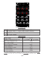
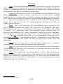
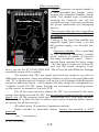
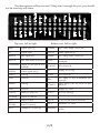
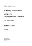
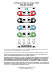
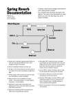
flight of harmony Eurorack Module ~rev1.0~ Components 1 Assembled Sound of Shadows digital delay module 1 DC power cable – 9” Ribbon cable (Doepfer standard) 4 M3x0.5x5mm Stainless-Steel machine screws 4 M3 Nylon washers Specifications Supply Voltage Supply Current ±12VDC IV+= 51mA (max draw @ ±12V) IV-= -21mA 10Vp-p Max. Input Voltage (@ ±12V) 6Vp-p Max. Output Voltage Input & Ouput (I/O) coupling Direct* Output Impedance 1kΩ Control Voltage (CV) inputs ±Vsupply CV input coupling Direct 100kΩ CV input impedance * I/O jacks are direct-coupled. The Delay circuit itself is not. A DC signal at the input will be available at the Clean, Mix, and VCA outputs, but not available at the delay output. 1/8 What is it? The Sound of Shadows (SoS) is a voltage-controlled (VC) digital delay module based around the PT2399 echo IC1 from Princeton Technology – which was, by the way, originally designed for Karaoke equipment. The SoS is essentially two separate modules: a delay and a voltage-controlled amplifier (VCA). The focus of the SoS was the delay while the VCA was thrown in because half of an LM13700 IC was unused, so the VCA is very basic. As with all f(h) products, the SoS was engineered towards maximizing functionality while keeping cost as low as possible. If some aspects of the unit seem awkward, it is most likely due to this. The goal is to make unique, useful, enjoyable, and affordable instruments, not just hoover2 out your bank account. And remember: every instrument has its quirks and unexpected aspects, so RTFM3! All the way through! Specific quirks are mentioned in the description of the particular feature they apply to, so please read this through before emailing! Sound of Shadows flowchart EXT x -1 Clean out Delay out x -1 EXT DELAY In VCA out In Out Mix out Mix Input VCA VCAIN jack Out Insert jack FEEDBACK In Out Feature summary: • • • • • Delay VC delay rate • VC feedback level • Signal input • Clean, Delayed, and Mix outputs Feedback loop insert jack VCA Input breakjack CV input Output The 30-pin header on the back of the module is for the SoS expansion module, currently in development. 1) Integrated Circuit 2) Hoover is a company that manufactures vacuum cleaners. 3) RTFM = Read The F*cking Manual! 2/8 Controls Rate: This controls the delay clock rate, which in turn controls how fast the delay steps through its memory array and thusly the amount of delay. Clockwise rotation increases the rate (which decreases the delay time), counter-clockwise decreases the rate (which increases the delay time). Feedback: Controls how much of the delayed signal is fed back into the delay cell. Feedback is what creates a reverberation or echo sound – multiple repetitions of an acoustic event. Clockwise rotation increases the amount fed back, and thus the number of repeats, counter-clockwise decreases the amount. The nominal operating area is between 6:00 and 9:00 during normal usage. More than this will set up a self-propagating feedback cycle that will quickly get out of hand. Insert: This is the attenuator for the feedback loop insert jack. The jack is situated between the delay cell output and the feedback cell input. The feedback cell input is calibrated for the output of the delay cell, which is around 1.5Vp-p maximum, and most standard signals inserted here will overload the feedback cell unless attenuated, hence the Insert attenuator. Turn clockwise to increase the signal level, counter-clockwise to attenuate. When not using the Insert jack, it is recommended to keep this control turned fully clockwise, to the maximum position. Otherwise, you are attenuating the output of the delay cell, which will affect everything else further down the signal path. Input: This is the input level control. Just like a volume knob – clockwise increases level, counter-clockwise attenuates the signal level. Mix: Um, yeah. Guess what this controls? The balance of the mixed signal at the Mix output! Seriously, this controls the mix between the Clean and Delay signals at the Mix jack, really! VCA: This controls the VCA output level – A.K.A.4: the volume knob. Standard behavior with a minor quirk – this control will not fully attenuate the output, but a negative CV applied to the VCA CV input will bring the level much further down. It was either this or add another IC + associated components to the PCB and jack the price further up. 4) A.K.A. = Also Known As 3/8 fig.1 Jacks The jacks are grouped by the type and direction (into or out of the module) of the relevant signal. The VCA jacks are just labeled “VCA”, as the function of each is already described by what row they are in. CV in Rate: Quirk warning: Rate CV behavior is inverted. Negative increases rate, positive decreases. If that bugs you too much, just think of it as the delay CV input and the issue magically disappears! Positive increases the delay, and negative decreases the delay. Feedback: This works normally, positive CV increases feedback, negative decreases same. VCA: Same as feedback, positive CV increases the output level, negative attenuates it. Signal in Input: This is kind of important for a delay unit: you need a signal to delay, or else they’re somewhat dull effects. This is the jack where that signal is input into the delay. Insert: This is the feedback loop insert breakjack. Inserting a plug here will disconnect the output of the delay cell from the input of the feedback cell, with the inserted signal now going directly to the feedback gain cell. One use for this is to insert an effect – or even another delay unit (yes, they can be daisy-chained quite effectively) – into the feedback loop. To do this, patch the Delay out into the desired effect, and the output of the effect into the Insert jack. You may need to adjust the Insert level control (see above) for best sound. VCA: This is another breakjack. The input of the VCA is normalized (normally connected to) the Mix output. Inserting a jack here breaks that connection, enabling the VCA to be used completely independently of the rest of the module. Output Clean: A buffered and inverted copy of the input signal. Delay: The buffered & scaled output of the delay cell Mix: A linear mix of the Clean and Delay signals, the balance of which is set by the Mix control pot. VCA: Output of the VCA. 4/8 FBCV RTCV RTPTWPR CLKOUT SPARE2 RTCV(R) FBCV FBWPR(R) RTEPT3 VCACV(R) VCACV GND GND V- VCVACV SPARE3 FBIN VCAIN CLNDELMIX MIXVCA INVCLN DELFB V+ MIXOUT DELMIX VCAOUT IN (R) IN CLNMIX DELOUT Other connections Power: The power connector header is a 2x5 shrouded box header which accepts the standard Doepfer power cable. This header style is polarized, meaning the connector can only be inserted one way, to prevent connecting the power backwards and damaging the unit. This assumes that you are using either the supplied cable or one manufactured by Doepfer. Looking at the rear of the module, the negative supply (red stripe) is on the left, positive supply is on the right (see fig.2). Expansion Header: This is provided for an upcoming expansion module which contains a number of functions 1 fig.2 that were considered “extras” – that is, + beyond those required for basic usage – but feel free to make use of them for your own DIY5 needs. However, if you do so, you do this AT YOUR OWN RISK. We will not be held liable for damage caused by misuse of this module. PWR-E PWR-F Pins marked with “(R)” are signal inputs that are ready for use with no additional components. Some are already utilized via jacks on the panel (denoted with “(J)” in the description), however, and no provision has been made for proper mixing of additional inputs – which means that they should be considered as a “multiple” if used. The “(R)” means that they are connected to a summing resistor on the input of an opamp on the main PCB. Pins of the same name but without the “(R)” are connected to the same opamp input as the one with the “(R)”, but do not have a summing resistor, you must supply one. All f(h) summing inputs are standardized with 100k input resistors. This was done to allow the user to add as many inputs as desired (within reason of course), but all from one pin. All outputs have 1k protection/impedance resistors. Unless marked as described above, assume the terminal is NOT protected. “con.” = connection. 5) DIY = Do It Yourself 5/8 FBWPR(R) FBCV RTCV(R) FBCV RTEPT3 RTCV RTPTWPR VCACV(R) GND CLKOUT VCACV VCVACV V- SPARE2 GND SPARE3 VCAIN FBIN INVCLN MIXVCA DELFB Top row, left to right: V+ MIXOUT DELMIX CLNDELMIX IN DELOUT VCAOUT IN (R) CLNMIX The descriptions will be minimal, if they aren’t enough for you, you should not be messing with them. Bottom row, left to right: IN(R) Signal input (J) CLNMIX con. Clean buffer mix pot IN Signal input DELOUT Delay signal out (J) MIXOUT Mix signal out DELMIX con. Delay buffer mix pot MIXVCA con. Mix buffer VCA in DELFB con. Delay breakjack CLNDELMIX Wiper of mix pot mix buffer(R) VCAOUT VCA output (R) INVCLN Clean signal out (J) V+ Supply V+ (+12V) SPARE3 nothing VCAIN VCA input (R) GND Ground FBIN con. Delay IC out feedback cell input (R) SPARE2 nothing VCVACV (typo, sorry) v.ref. for VCA CV pot minimum GND Ground V- Supply V- (-12V) CLKOUT Delay IC clock out VCACV VCA CV input (J) RTPTWPR Wiper of rate pot VCACV(R) VCA CV input RTCV Rate CV input RTEPT3 v. ref. for rate control minimum RTCV(R) Rate CV input (J) FBCV Feedback CV input FBCV Feedback CV input (R) FBWPR(R) con. Feedback wiper FB level buffer 6/8 IC out insert Stuff There is a lot of discussion about the Sound of Shadows on the Muffwiggler forums, come check it out! People have posted some excellent demos on there. I haunt the forums as well, and new things are posted there long before they hit the f(h) website. http://www.muffwiggler.com/forum/index.php A big thank you to those who have sent in suggestions and comments, keep them coming! Send samples to: [email protected] Comments, suggestions, complaints to: [email protected] Drawings and designs ©2010 flight of harmony / Red Hand Studios http://www.flightofharmony.com Revised Feb, 2010. We are tomorrow’s shadows... 7/8 f(h) 8/8