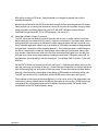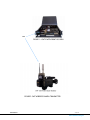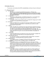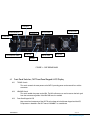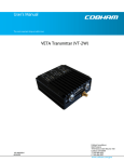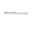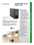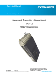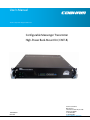
1
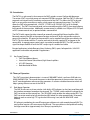
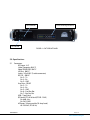
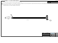
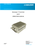
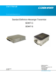
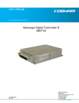
User’s Manual
The most important thing we build is trust.
Configurable Messenger Transmitter
High-Power Rack-Mount Kit (CMT-R)
100-M0076X1
05/22/09
Cobham Surveillance
GMS Products
1916 Palomar Oaks Way Ste 100
Carlsbad, CA 92008
T: 760-496-0055
F: 760-496-0057
www.cobham.com/gms
Table of Contents
1.0 Acronyms................................................................................................................................................................... 4
2.0 Introduction............................................................................................................................................................ 5
2.1
Key System Features ...........................................................................................................................................5
3.0 Theory of Operation .......................................................................................................................................... 5
3.1
Rack Mount Operation........................................................................................................................................5
3.2
Stand Alone Wireless Camera Transmitter ................................................................................................6
4.0 Hardware Overview ............................................................................................................................................ 8
4.1
Rear Panel Connectors........................................................................................................................................8
4.1.1 RF Output (J9) ....................................................................................................................................................8
4.1.2 AC Input (J11)....................................................................................................................................................8
4.1.3 DC Power (J10)..................................................................................................................................................8
4.1.4 RS-232 (J7)..........................................................................................................................................................8
4.1.5 USB (J8) ................................................................................................................................................................8
4.1.6 User Data (J6).....................................................................................................................................................8
4.1.7 Audio Connectors (J4 & J5)..........................................................................................................................8
4.1.8 HD/SD SDI IN (J2) ............................................................................................................................................8
4.1.9 ASI Out (J1).........................................................................................................................................................8
4.1.10 Comp Video (J3) ...............................................................................................................................................8
4.2
Front Panel Switches, CMT Front Panel Keypad & LCD Display .......................................................9
4.2.1 TX PWR Switch.................................................................................................................................................9
4.2.2 HPA PWR Swtich...............................................................................................................................................9
4.2.3 Front Panel Keypad & LCD............................................................................................................................9
5.0 Specifications...................................................................................................................................................... 10
5.1
Connectors............................................................................................................................................................10
5.2
Control....................................................................................................................................................................11
5.3
COFDM RF Output.............................................................................................................................................11
5.4
AC Power ...............................................................................................................................................................11
5.5
DC Power ...............................................................................................................................................................11
5.6
Physical...................................................................................................................................................................11
5.7
Environmental .....................................................................................................................................................11
100-M0076X1
2 of 12
www.cobham.com/gms
List of Figures
FIGURE 1 – CMT-R WITH FRONT LID OPEN............................................................................................................... 7
FIGURE 2- CMT WIRELESS CAMERA TRANSMITTER ............................................................................................. 8
FIGURE 3 – CMT-R REAR PANEL....................................................................................................................................... 9
FIGURE 4 – CMT-R FRONT PANEL.................................................................................................................................10
Appendix
APPENDIX A – AI, CABLE, EXTERNAL BREAKOUT...................................................................................................12
100-M0076X1
3 of 12
www.cobham.com/gms
1.0 Acronyms
This section lists and describes the various acronyms used in this document.
Name
16 QAM
64 QAM
A/V
AES
ASI
BDC
COFDM
CVBS/Y
C
CML
CMT
D/C
DRL
DVB-T
FEC
ENG
GUI
HD
HPA
I/O
Kbaud
Kbps
Mbps
MER
MPEG
MSR
NTSC
PAL
QPSK
RCU
RF
RX
SDI
S/N
THD
TX
UAV
UGV
VDC
100-M0076X1
Meaning
16-state Quadrature Amplitude Modulation
64-state Quadrature Amplitude Modulation
Audio/Video
Advanced Encryption System (32 bit)
Asynchronous Serial Interface
Block down converter
Coded Orthogonal Frequency Division Multiplexing
Composite video/Luminance with S-video
Chroma video
Configurable Messenger Link
Configurable Messenger Transmitter
Down-Converter
Data Return Link
Digital Video Broadcasting-Terrestrial
Forward Error Correction
Electronic News Gathering
Graphical User Interface
High Definition
High Power Amplifier
Input/ Output
Kilobaud per second
Kilobits per second
Megabits per second
Modulation Error Rate
Moving Picture Experts Group
Messenger Smart Receiver
National Television System Committee
Phase Alternation Line
Quadrature Phase Shift Keying
Remote Control Unit
Radio Frequency
Receiver
Serial Digital Interface
Signal-to-Noise Ratio
Total Harmonic Distortion
Transmitter
Unmanned Aerial Vehicle
Unmanned Ground Vehicle
Volts (Direct Current)
4 of 12
www.cobham.com/gms
2.0 Introduction
The CMT-R is a rack-mount kit that converts the GMS’s wireless camera Configurable Messenger
Transmitter (CMT) into a high-power rack-mounted COFDM transmitter. Both the CMT-R’s front and
top panels are hinged for easy installation and removal of the CMT. This allows the CMT to be used
both as an on-camera transmitter as well as a high-power rack-mounted transmitter. The CMT-R
allows the CMT to be powered with +28 VDC, +12 VDC or 85-256 VAC @ 47 to 63 Hz (Model
dependant). The CMT’s local control panel can be accessed through the CMT-R’s front panel allowing
local control of the transmitter. Additionally, remote control is available via a USB port, a RS-232 port,
an RCU (remote control unit) or optional wireless command link.
The CMT-R adds support for either internally or externally mounted High Power Amplifier (HPA).
Remotely mounting the HPA at the antenna location minimizes RF losses and provides maximum
power to the Antenna. DC power for the external PA can be supplied through the coax cable by the
CMT-R. This kit includes two Bias-Ts, one for each end of the coax supplying RF and power to the
remote HPA. A separate power control switch is provided to enable the HPA. The CMT provides a
signal that keeps the HPA off until the CMT’s output signal is enabled and stable.
Principal applications include Electronic News Gathering (ENG), sports, helicopter links, UAV/UGV
applications and mobile and portable AV applications.
2.1
Key System Features
• CMT Quick Release Mount
• Internal or External (Mast Mount) High-Power Amplifiers
• AC & DC Operation
• Rack-Mountable W/Slides
3.0 Theory of Operation
The CMT (transmitter) documentation is in manual 100-M0071 which is on-line at GMS web site,
WWW.GMSINC.COM . The manual documents in detail the operation of the transmitter, the use of
the PC control application software and the connectors. It contains valuable information which will
help in getting the most use out of the CMT-R.
3.1
Rack Mount Operation
The CMT-R rack consists of two switches (with built in LED indicators) on the front panel along with
the interface connectors located on the rear panel. The ‘TX PWR’ switch enables the voltage to the
CMT transmitter and the internal fans. The ‘ HPA PWR’ switch enables the voltage to the HPA. The
CMT transmitter needs to be fully initialized and PLL locked (this takes approximately 30 seconds)
before it sends an active high TTL signal to the HPA turning it on (with the ‘HPA PWR” switch
enabled).
DC voltage is provided on the same RF output coax cable on units with remotely located HPA. This
configuration requires a DC extractor on the HPA end. The coax cable must be capable of handling
the large current drive (approximately 8 to 10 amps) required by the
100-M0076X1
5 of 12
www.cobham.com/gms
HPA and have minimum DC losses. Careful attention must be paid to properly heat sink the
remotely located HPA.
Monitoring and control of the CMT-R can be done through the front panel keypad and LCD display.
Some controls such as setting user attenuation, turning on user data or encryption, changing video
group parameters and others require the use of a PC with GMS’s Windows control software
interfaced through the rear RS-232 or USB connectors (see section 4.1).
3.2
Stand Alone Wireless Camera Transmitter
The CMT transmitter can be easily removed from the rack to use as a wireless camera transmitter.
Before taking the transmitter out of the rack it is necessary to reduce the ‘User Attenuation’ value in
order to bring the transmitter up to full power. Establish communication with the transmitter using
the PC software application control using a serial cable (or USB cable) connected to the appropriate
rear connector (see section 4.0 for connector locations). Once communication is established go to
the ‘Others’ screen which is under the ’Special Setup’ menu under the ‘Configuration’ menu in the
main window. Note the current value in the ‘Set User Attenuation Step Upper Limit’ text box. You
will need to set it back to this value before re-installing the transmitter. Change this value to ‘0’ for
no attenuation. Save the settings and exit the program. Turn off both CMT-R switches (Tx Pwr and
HPA Pwr).
Pull the CMT-R all the way forward out the rack (see Figure 1). Undo the quick release screws on the
top cover and swing it up and out of the way. Unscrew the two thumbscrews on the front panel and
let it roll forward giving you easily access to the transmitter. Ensure to disconnect all cables before
releasing it from the battery mount plate (Anton Bauer or IDX) located on the bottom of the rack.
The CMT can now be used as a stand-alone wireless HD/SD camera transmitter (see Figure 2).
The installation is the reverse of the removal process. Just be sure to set the ‘User Attenuation’ back
to the factory setting value otherwise the HPA may be overdriven causing the C-OFDM signal to go
into compression causing poor performance. In addition the three-position CMT power switch
should be left in the ‘ON’ (external power) setting.
100-M0076X1
6 of 12
www.cobham.com/gms
CMT
FIGURE 1 – CMT-R WITH FRONT LID OPEN
FIGURE 2- CMT WIRELESS CAMERA TRANSMITTER
100-M0076X1
7 of 12
www.cobham.com/gms
4.0 Hardware Overview
The connectors and switches of the CMT-R are detailed below and shown in Figure 3 and Figure 4.
4.1 Rear Panel Connectors
4.1.1 RF Output (J9)
The CMT-R uses a female ‘N’ type bulkhead connector for its ‘RF Ouput’ port.
Note: This port should be properly terminated (with an antenna or attenuator)
before enabling the power to the HPA. Damage to the unit could occur without
the proper termination.
4.1.2 AC Input (J11)
A three-prong module connector is provided for AC power. This is a universal AC power
supply which can handle the voltage range from 85 to 256 VAC at 47 to 63 Hz.
4.1.3 DC Power (J10)
A standard 4 pin PTO connector (PTO2E-12-4P) is provided for DC voltage input. Pins A&B
are used for +Vcc and pins C&D are used for ground.
4.1.4 RS-232 (J7)
A 9-pin female dB connector is provided for interfacing the CMT-R to the PC using GMS’s
PC Windows application control software. A standard 9 pin serial cable can be used
between the PC and the CMT-R.
4.1.5 USB (J8)
A USB (1.0) type B jack is provided and serves the same purpose as the RS-232 connector
above since most new computers only contain USB ports. Special USB drivers are shipped
with GMS’s PC control software that need to be loaded before using this port. The
transmitter should be fully booted and initialized before plugging in the USB cable between
the PC and the CMT-R. This port is not active until the transmitter is fully booted and
initialized.
4.1.6 User Data (J6)
A 9-pin female dB connector is provided for user data. If the transmitter is equipped (and
setup) to handle user data the serial data can be injected into this port.
4.1.7 Audio Connectors (J4 & J5)
Two 3 pin XLR –F connectors are provided to handle the balanced audio 1 and audio 2
input channels. The audio signal can be set for line or mic levels.
4.1.8 HD/SD SDI IN (J2)
A female BNC connector is provided for SD-SDI or HD-SDI video input streams (75 ohm
impedance). The input bit rate is 270 Mbps for SD and 1.485 Gbps for HD.
4.1.9 ASI Out (J1)
A female BNC connector is provided for DVB-ASI transport stream output (75 ohm
impedance). The output bit rate is 270 Mbps. This transport stream does not include the SI
tables, User-Data or AES encryption which is added later in the processing chain. This port
is also useful for troubleshooting. The ASI stream output from this port can be taken
directly into the ASI input of a decoder showing the status of the encoder bypassing any
RF processing.
4.1.10 Comp Video (J3)
A female BNC connector is provided for composite video input (75 ohm impedance). In
order for the transmitter to recognize composite video it must be set for SD (standard
definition) mode by selecting the correct Video Group from the front panel of the CMT-R
or using the PC control software through the RS-232 or USB ports.
100-M0076X1
8 of 12
www.cobham.com/gms
J5 Audio 1
J2 HD/SD SDI IN
J4 Audio 2
J11 AC Input
J6 User Data
J1 ASI OUT
J3 Composite Video
J7. RS-232
J10 DC PWR
J9 RF Out
J8 USB
FIGURE 3 – CMT-R REAR PANEL
4.2
Front Panel Switches, CMT Front Panel Keypad & LCD Display
4.2.1
TX PWR Switch
This switch controls the main power to the CMT-R, providing power to the internal fans and the
transmitter.
4.2.2
HPA PWR Swtich
This switch enables the power to the HPA. The HPA will not turn on until it receives the lock signal
from the transmitter regardless if the HPA PWR switch in enabled.
4.2.3
Front Panel Keypad & LCD
Most control and monitoring of the CMT-R can be done with the 4 button keypad and the LCD.
Full operation is detailed in the CMT manual 100-M0071 as stated above.
100-M0076X1
9 of 12
www.cobham.com/gms
HPA PWR SW
Front Panel Keypad & LCD
TX PWR SW
FIGURE 4 – CMT-R FRONT PANEL
5.0 Specifications
5.1
Connectors
RF Output: N-F
Video Composite: BNC-F
Video SDI/HD-SDI: BNC-F
ASI Out: BNC-F
Audio: 3 Pin XLR-F (2 audio connectors)
RS-232 – DB-9 F
Pin 2 – Tx
Pin 3 – Rx
Pin 5 – GND
User Data – DB-9 F
Pin 2 – Tx
Pin 3 – Rx
Pin 5 – GND
Pin 6 – Fwd Pwr Det
Pin 7 – Rev Pwr Det
USB – Type B Jack
DC Power: PTO 4P M Jack (PTO2E-12-4P)
Pin A&B: +Vcc
Pin C& D: GND
AC Power: 3 Prong module (10 Amp fused)
85-256 VAC (47-63 Hz)
100-M0076X1
10 of 12
www.cobham.com/gms
5.2
5.3
5.4
5.5
5.6
5.7
Control
RS-232 3-wire interface (Tx,Rx,Gnd)
USB
1.0
RCU
A remote portable control unit
Optional Wireless command link available
A MS Windows based control application running on XP or Windows 2000 operating systems is
used to control the transmitter.
C-OFDM RF Output
Output Frequency: 1 to 7 GHz (In-Bands)
RF Output Power: Up to 15 W (Model Dependant)
AC Power
120 VAC @ < 1 amp
DC Power
DC Voltage +12VDC: 9-15 V range ( @ 9 – 11 amps, model and video input dependant)
DC Voltage +28VDC:
Physical
Dimensions:
16” (W) x 16.94” (D) x 3.5” (H)
40.64 cm (W) x 43.03 cm (D) x 8.89 cm (H)
Width with handles 18.658” / 47.391 cm
Weight: 15.4 lbs (6.99 kgs)
(without CMT transmitter)
Environmental
Operational Temperature: -10 to +70 °C
Humidity: Up to 100% (non-condensing)
100-M0076X1
11 of 12
www.cobham.com/gms
APPENDIX A – AI, CABLE, EXTERNAL BREAKOUT
REVISIONS
NOTES:
1.1.
REFERENCE BOM 780-AI0056 FOR PART REFERENCE DESIGNATORS
1.2
LABEL THE CABLE ASSEMBLY WITH "780-AI0056X1" USING BEST COMMERCIAL METHOD APPROXIMATELY WHERE SHOWN AND COVER WITH CLEAR SHRINK WRAP.
1.3.
REFERENCE SHEET 1 FIGURE 1 FOR CABLE WIRING DIAGRAM.
1.4.
REFERENCE SHEET 2 FOR CABLE ASSEMBLY INSTRUCTIONS.
ECO
REV
DESCRIPTION
DATE
APPROVED
E0676
X1
INITIAL RELEASE
12/14/06
APPROVED
1.2
A
B
CIG LIGHTER
16AWG CSA TYPE SPT-2
16AWG CSA TYPE SPT-2
16AWG CSA TYPE SPT-2
C
D
FIGURE 1
P1
ENG/TECH
DRAWN
ENG
T GIOTTA
DWG TITLE
T GIOTTA
GMS Products
SIZE
QC
DATE
12/14/06
PROD
SCALE
NONE
AI,CABLE, CMT-R, +12VDC, PWR EXTERNAL WITH
CIG LIGHTER END
DWG NO
REV
780-AI0056X1
X1
SHEET
12 of 12
1 OF 3