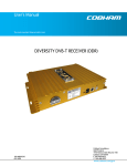
1
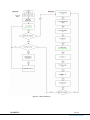
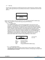
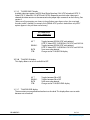
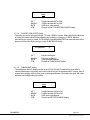
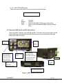
User’s Manual
The most important thing we build is trust.
Inline Camera Mount
- Broadcast Version -
100-M0058X2
06/18/09
Cobham Surveillance
GMS Products
1916 Palomar Oaks Way Ste 100
Carlsbad, CA 92008
T: 760-496-0055
F: 760-496-0057
www.cobham.com/gms
TABLE OF CONTENTS
1.0 ACRONYMS................................................................................................................................................................... 3
2.0 INTRODUCTION .................................................................................................................................................... 4
3.0 FRONT CONTROL PANEL OPERATION ................................................................................................... 4
3.1 Menu Structure....................................................................................................................................................... 4
3.1.1 Power Up .......................................................................................................................................................... 6
3.1.2 Main Menu....................................................................................................................................................... 6
3.1.2.1 Channel Display......................................................................................................................................... 6
3.1.2.2 Enter Detail Menu Display .................................................................................................................... 6
3.1.2.3 Exit MDT-B Control Display ................................................................................................................. 7
3.1.2.4 Enter MDT-B Transmitter Display...................................................................................................... 7
3.1.3 Detail Menu ..................................................................................................................................................... 7
3.1.3.1 TX COFDM MODE display..................................................................................................................... 8
3.1.3.2 TX COFDM BANDWTH display ........................................................................................................... 8
3.1.3.3 TX GUARD INTERVL display................................................................................................................. 8
3.1.3.4 TX MOD FEC display................................................................................................................................ 8
3.1.3.5 TX VIDEO INPUT display....................................................................................................................... 9
3.1.3.6 TX AUDIO ON display ............................................................................................................................. 9
3.1.3.7 TX AUDIO LEVEL display ....................................................................................................................... 9
3.1.3.8 TX AUDIO GAIN ADJUST display ....................................................................................................10
3.1.3.9 TX BACKLIGHT display .........................................................................................................................10
3.1.3.10 EXIT DETAIL MENU display...........................................................................................................11
4.0 CONNECTORS/PWR SWITCH AND LCD CONTROL PANEL.................................................... 11
4.1 RF Output ................................................................................................................................................................12
4.2 I/O...............................................................................................................................................................................12
4.3 Video Input.............................................................................................................................................................12
4.4 Power Switch .........................................................................................................................................................12
4.5 LCD Display.............................................................................................................................................................13
4.6 SDI Input (optional)............................................................................................................................................13
LIST OF TABLES
Table 1 - I/O DB-15 Connector Pin Out........................................................................................................... 11
100-M0058X2
2 of 13
www.cobham.com/gms
1.0 Acronyms
This section lists and describes the various acronyms used in this document.
Name
16QAM
64 QAM
A/V
C-OFDM
CVBS
Y
C
Pr
Pb
FEC
MDT-B
MPEG
NTSC
PAL
QPSK
RF
SDI
TX
100-M0058X2
Meaning
16-state Quadrature Amplitude Modulation
64-state Quadrature Amplitude Modulation
Audio/Video
Coded Orthogonal Frequency Division Multiplexing
Color video base band signal (Composite video).
Luminance video
Chromaince video
Red Chromaince
Blue Chromaince
Forward Error Correction
Messenger Digital Transmitter, Broadcast Version
Moving Picture Experts Group
National Television System Committee
Phase Alternation Line
Quadrature Phase Shift Keying
Radio Frequency
Serial Digital Interface
Transmitter
3 of 13
www.cobham.com/gms
2.0 Introduction
The inline camera mount box is an optional housing (for the MDT-B transmitter) which mounts to a
professional A/V camera. The housings are designed to use either Anton Bauer or IDX batteries.
The two line LCD (liquid crystal display) provides visual readouts of transmitter frequency, analog video
lock status, COFDM mode, COFDM bandwidth, transmitter guard interval, forward error correction (FEC),
video input type, audio status, audio gain and backlight status.
In addition the front control buttons allows the most common available options (as described later in this
document) to be changed from the front panel. If necessary the transmitter can still be accessed with the
use of a PC using GMS control software through the 15-pin DB connector. Refer to MDT-B operation
manual (100-M0056, found on GMS web site www.gmsinc.com) for detailed description of the external
control software.
3.0 Front Control Panel Operation
The front control panel consists of a two line LCD (liquid crystal display) and four control buttons, the
CTRL, ENTR, ↑ (up arrow), and ↓ (down arrow), see figure 1. In general, the up and down arrow buttons are
for selecting available options, the CTRL button is for moving between menus and the ENTR button is for
saving new values (as selected with the up and down arrow buttons).
Figure 1 –Front Control Panel
3.1 Menu Structure
The overall menu structure is demonstrated as a flowchart in Figure 2. Refer to this figure as the following
individual displays are explained in detail.
100-M0058X2
4 of 13
www.cobham.com/gms
Figure 2 – Menu Flowchart
100-M0058X2
5 of 13
www.cobham.com/gms
3.1.1
Power Up
On power up the LCD displays the “GMS” logo and firmware number and then the “Initializing” display
appears. It takes approximately 35 seconds before communications is established for the first time on
power up.
GMS RCU2000 G108
↓
MDT-B IS
INITIALIZING
[Note: If communications cannot be established for some reason the LOST MDT-B COMM display
appears. Re-try establishing communications by pressing the ENTR button.]
3.1.2 Main Menu
3.1.2.1 Channel Display
The CHANNEL display appears after the front panel establishes communication with the
transmitter . In this mode when the ↑ UP or ↓ DOWN button is pressed the transmitter steps
through the available channels. The display blinks for ten seconds after releasing the button. If
ENTR button is pressed before ten seconds, the frequency changes and is stored in nonvolatile
memory. If ENTR is not pressed before ten seconds, the display will stop blinking and the
transmitter will reset to the previous frequency. In addition, on the second line of the LCD the
video type and status is displayed. If no video is detected the message “NO VIDEO INPUT” is
displayed. Note: This message does not apply when the video input mode is set to SDI .The
channel display and control functions are shown below (underline words are meant to
demonstrate variables which are subject to change depending on values chosen).
TX 2500 MHz
Composite, NTSC
UP ↑
DOWN ↓
ENTR
CTRL
Channel Display
with video
Increment channel
Decrement channel
Saves channel
Change to ENTER DETAIL MENU display
3.1.2.2 Enter Detail Menu Display
This display window allows user to enter a detail submenu in which variables such as COFDM
mode, bandwidth guard interval, FEC (forward error correction), video input type, audio parameters
and backlight options are available.
100-M0058X2
6 of 13
www.cobham.com/gms
ENTER DETAIL MENU
UP ↑
DOWN ↓
ENTR
CTRL
Enter detail
menu display
No effect
No effect
Enters detail menu TX COFDM MODE display
Change to EXIT MDT-B CTRL display
3.1.2.3 Exit MDT-B Control Display
This display allows user to either return to the CHANNEL display of the main menu or exit control
of the MDT-B from the front LCD control panel. This is necessary when connecting to the camera
mount housing through the DB-15 connector with a PC using GMS control software.
EXIT MDT-B CTRL
UP ↑
DOWN ↓
ENTR
CTRL
Exit MDT-B CTRL
display
No effect
No effect
Exits control of MDT-B and enters ENTER MDT-B
TRANSMITTER display
Returns to CHANNEL display
[Remember: If external PC control using GMS Control software is to be used you must first EXIT
MDT-B CTRL before attempting to connect through the DB-15 connector.]
3.1.2.4 Enter MDT-B Transmitter Display
This display allows user to re-enter the CHANNEL display of the main menu and returns control to
the front LCD control panel.
ENTER MDT-B
TRANSMITTER
UP ↑
DOWN ↓
ENTR
CTRL
No effect
No effect
Enters the CHANNEL display
No effect
3.1.3 Detail Menu
The detail menu presents various displays for changing available options as explained in detailed below.
When a new value is selected the TX letters in the display window will blink indicating a change is in
process. It will stop blinking after the ENTR button is pressed (saving the new value) or exiting the display
(without saving the new value) by pressing the CTRL button.
100-M0058X2
7 of 13
www.cobham.com/gms
3.1.3.1 TX COFDM MODE display
This display allows user to choose from three available COFDM modes, QPSK, 16QAM or 64QAM.
TX COFDM MODE
QPSK
UP ↑
DOWN ↓
ENTR
CTRL
Toggles between QPSK, 16QAM and 64QAM
Toggles between QPSK, 16QAM and 64QAM
Saves new value selected
Changes to the TX COFDM BANDWTH display
3.1.3.2 TX COFDM BANDWTH display
COFDM bandwidth can be adjusted from this display selecting from 6, 7 or 8 MHz.
TX COFDM BANDWTH
8MHz
UP ↑
DOWN ↓
ENTR
CTRL
Toggles between 6, 7 or 8 (MHz)
Toggles between 6, 7 or 8 (MHz)
Saves new value selected
Changes to the TX GUARD INTERVL display
3.1.3.3 TX GUARD INTERVL display
Guard interval options, 1/32, 1/16,1/8 and ¼ are selected from this display.
TX GUARD INTERVL
1/16
UP ↑
DOWN ↓
ENTR
CTRL
Toggles between 1/32,1/16,1/8 and 1/4
Toggles between 1/32,1/16,1/8 and 1/4
Saves new value selected
Changes to the TX MOD FEC display
3.1.3.4 TX MOD FEC display
FEC (Forward Error Correction) code rates, ½,2/3,3/4,5/6, and 7/8 are selected from this display.
TX MOD FEC
1/2
UP ↑
DOWN ↓
ENTR
CTRL
100-M0058X2
Toggles between ½,2/3,3/4,5/6,7/8
Toggles between ½,2/3,3/4,5/6,7/8
Saves new value selected
Changes to the TX VIDEO INPUT display
8 of 13
www.cobham.com/gms
3.1.3.5 TX VIDEO INPUT display
Available video input options are SDI (Serial Digital Interface), PAL, NTSC w/pedestal, NTSC, SVideo NTSC, S-Video PAL, YUV NTSC and YUV PAL. Depending on which input video type is
selected the video source must be connected to the proper input connectors on the housing. See
section 4.
[Note: not all input options are shown in the pull down menu boxes unless the associated
encoder profile is loaded. For example if the SP@ML NTSC profile is loaded then only NTSC
options appear in the pull down menu boxes].
TX VIDEO INPUT
NTSC w/PEDESTAL
UP ↑
DOWN ↓
ENTR
CTRL
Toggles between SDI,PAL,NTSC with pedestal,
NTSC, S-Video NTSC, S-VIDEO PAL YUV NTSC and YUV PAL
Toggles between SDI,PAL,NTSC with pedestal,
NTSC, S-Video NTSC, S-VIDEO PAL YUV NTSC and YUV PAL
Saves new value selected
Changes to the TX AUDIO ON display
3.1.3.6 TX AUDIO ON display
This display allows user to turn audio ON or OFF.
TX AUDIO ON
UP ↑
DOWN ↓
ENTR
CTRL
Toggles between ON or OFF
Toggles between ON or OFF
Saves new value selected
Changes to the TX AUDIO LEVEL display
3.1.3.7 TX AUDIO LEVEL display
The transmitter can accept balanced audio mic or line level. This display allows user to switch
between mic or line level.
100-M0058X2
9 of 13
www.cobham.com/gms
TX AUDIO LEVEL
LINE
UP ↑
DOWN ↓
ENTR
CTRL
Toggles between MIC or LINE
Toggles between MIC or LINE
Saves new value selected
Changes to the TX AUDIO GAIN ADJUST display
3.1.3.8 TX AUDIO GAIN ADJUST display
The audio gain can be adjusted with the ↑ UP and ↓ DOWN buttons. When adjusting the level the
A1 letters on the left side will blink indicating that a change is in progress. If ENTR button is
pressed the gain setting is stored. If CTRL button is pressed before ENTR the audio will reset to the
previous level and the display changes to the TX BACKLIGHT display.
AI |||||||||||||||||||||||
UP ↑
DOWN ↓
ENTR
CTRL
50
Increase audio gain
Decreases audio gain
Saves gain level selected
Changes to TX BACKLIGHT display
3.1.3.9 TX BACKLIGHT display
The backlight on the LCD display can be set to AUTO or ON. AUTO mode will activate when a
control panel button is activated (any button) and will stay on for approximately 5 minutes. After 5
minutes the backlight will shut down until a control panel button is activated once again. ON mode
will leave the backlight always turned on.
TX BACKLIGHT
AUTO
UP ↑
DOWN ↓
ENTR
CTRL
100-M0058X2
Toggles between AUTO or ON
Toggles between AUTO or ON
Saves new value selected
Changes to EXIT DETAIL MENU display
10 of 13
www.cobham.com/gms
3.1.3.10 EXIT DETAIL MENU display
Allows user to exit to Main Menu or to return to beginning of Detail Menu.
EXIT DETAIL MENU
UP ↑
DOWN ↓
ENTR
CTRL
No effect
No effect
Returns to EXIT MDT-B CTRL display of Main Menu
Returns to TX COFDM MODE display, beginning of Detail
Menu.
4.0 Connectors/PWR Switch and LCD Control Panel
There are four BNC connectors, two audio XLR, one DB-15 connector, one N type connector and one
rocker on/off power switch located on the MDT-B inline camera unit for interfacing the RF, audio,
video, power and RS-232 signals.
Balance
audio,
A1&A2
DB-15
Connector
BNC J2=Chroma C
video input when
used with S-video.
When used with
Component video =
BNC J7 = SDI
input.
BNC J3, Y/COMP
=Composite video
input. When used with
S or Component video
= Luminance input
RF out
Power
“on/off”
switch.
BNC J8 = Pb when
used with
Component video.
LCD panel with controls
Figure 3 - MDT-B Inline Camera Unit
100-M0058X2
11 of 13
www.cobham.com/gms
4.1
RF Output
The MDT inline camera enclosure uses a female N type connector (flange mount) for its
‘RF Output’ port.
4.2
I/O
The ‘I/O’ connector is a female, DB-15. It is used to provide the interface for RS-232
signals (control and monitoring). GMS MDLB Configurator software program makes use
of the RS232 control lines, pins 2, 3 and 5 of the DB-15 connector. The RS-232 channel
utilizes a 3-wire configuration. The pin out for I/O connector is shown in Table 2.
A USB connector is currently provided with the external serial cable which is an
alternate method of interfacing to the PC if DB-9 connectors are not available.
Table 1 - I/O DB-15 Connector Pin Out
Pin
1
2
3
Signal
+12Vdc
RS232-Rx (CTRL)
RS232-Tx (CTRL)
4
5
Not connected
RS232-GND
6
7
8
9
10
11
12
13
14
15
I^2C_D
I^2C_C
USB Reset
USB Data USB Data +
USB GND
Not connected
RS232-Tx (DATA)
RS232-Rx (DATA)
RS232-GND
Notes
Relative to MDT (i.e., control data is input on this pin)
Relative to MDT (i.e., control data is output on this
pin)
Common ground for both RS232 Data and Control
lines
+5Vdc
Under development/for future updates
Under development
Under development
4.3
Video Input
The MDT–B inline camera enclosure uses female BNC connectors for video input.
Component, Composite or S-Video input is accepted (see section 3.1.3.5 for setting
video input type). J3 BNC connector marked “Y/COMP” is a dual use input connector; a)
Composite Video or b) Luminance when used with Component video. J2 BNC connector
marked “C/Pr” is a dual use input connector; a) Chroma when used with S-Video or b) Pr,
the red component minus the luminance information used with Component Video. J8
BNC connector marked “Pb” is the blue component minus the luminance information
used with Component Video.
4.4
Power Switch
An LED indicator rocker switch is provided for controlling power to the unit.
100-M0058X2
12 of 13
www.cobham.com/gms
4.5
LCD Display
Many of the control functions which are normally handled through the software
interface and a PC are accessed directly with the front control panel and displayed on the
LCD.
4.6
SDI Input (optional)
A BNC connector is provided for Serial Digital Interface input data stream.
100-M0058X2
13 of 13
www.cobham.com/gms