1
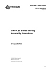
Appearance, board layout
There are three Molex microfit connectors, two jumpers and one trimmer
potentiometor on Pockels cell driver board. The description is below.
“ENABLE” JUMPER:
“ENABLE” JUMPER can be used instead of “ENABLE” signal (PIN4 of
INTERFACE). Do not use “ENABLE” JUMPER and “ENABLE” signal at
the same time.
“HV PROGRAM” JUMPER AND “HV PROGRAM” TRIMPOD:
Use “HV PROGRAM” JUMPER instead of “HV PROGRAM” signal (PIN6
of INTERFACE). If jumper is on it sets output voltage accordingly to
“HV PROGRAM” TRIMPOT state. Do not use “HV PROGRAM”
JUMPER and “HV PROGRAM” signal at the same time.
+24V (Molex microfit 2x2):
+24V
4 3
2 1
PIN (color)
DESIGNATION
DESCRIPTION
1, 2 (red)
+24V
INPUT positive (+24VDC to turn on the
Pockels cell driver)
3, 4 (black)
RETURN
Return from power supply producing
+24VDC
INTERFACE (Molex microfit 2x3):
Interface
6 5 4
3 2 1
PIN (color)
DESIGNATION
1 (orange)
Q-switch
2, 5 (black)
Interface Return
3 (yellow)
HV Monitor
DESCRIPTION
Step from “0” or ”1” on PIN1 forms
Q-Switched pulse on Pockels Cell
PIN2 and PIN5 are connected to the circuit
ground of all internal circuits
The voltage at PIN3 is a monitor signal
proportional to the measured value of high
voltage output
HVmax corresponds to 10V at PIN3,
HVmin corresponds to approx. 4V at PIN3
4 (blue)
6 (green)
Enable
HV Program
The high voltage output is enabled by PIN4
(“1” – enable, “0” – disable)
Positive DC voltage applied to PIN6 sets up
high voltage value HV
HVmax corresponds to 10V at PIN6,
HVmin corresponds to approx. 4V at PIN6
“0” means logical 0 low level (0V), “1” means logical 1 high level (5V)
INTERFACE CIRCUITS
Q-Switch
HV Monitor
Enable
HV Program
HV OUTPUT (Molex microfit 2x3):
HV Output
6 5 4
3 2 1
QBD-mini, UP-modification
PIN (color)
DESIGNATION
1 (blue)
Negative
2-5
N/C
6 (red)
Positive
DESCRIPTION
HV Negative
HV Positive
QBD-mini, DN-modification
PIN (color)
DESIGNATION
1 (red)
Positive
2-5
N/C
6 (blue)
Negative
DESCRIPTION
HV Positive
HV Negative
Safety
Warning! This equipment produces high voltages that can be very
dangerous. Don’t be careless around this equipment.
•
•
•
•
To provide safety the QBD-series Pockels cell driver module is designed to be powered
with supply voltage +24VDC, which must be galvanically separated from mains.
It is the user’s responsibility to ensure that personnel are prevented from accidentally
contacting the QBD-series Pockels cell driver module, especially the high voltage
connector and cable. Casual contact could be fatal. Output cables must have good
isolation for output voltage and low capacitance.
After shut down, do not touch the load until it has been discharged. Use an appropriate
measurement device to check for complete discharge.
Disconnect the QBD-series Pockels cell driver module from DC power supply before
changing electrical or mechanical connections.
Operations (Manual control)
1.
2.
3.
4.
5.
6.
7.
Connect +24VDC power supply, pulse generator and Pockels cell
Set up “HV PROGRAM” JUMPER
Turn on +24VDC power supply
Set up “ENABLE” JUMPER
Use “HV PROGRAM” TRIMPOT to set up required output voltage
Send driving pulses from pulse generator to PIN1 of INTERFACE
To power down the driver, turn off +24VDC power supply or remove
“ENABLE” JUMPER
Operations (Automatic control)
1.
2.
3.
4.
5.
Connect +24V, INTERFACE and HV OUTPUT connectors to the board.
Remove “HV PROGRAM” JUMPER, remove “ENABLE” JUMPER
DISABLE the high voltage output
Apply +24VDC to the Pockels cell driver
Set up the desired output voltage by applying the corresponding
DC voltage to PIN6 of INTERFACE (HV PROGRAM)
6. ENABLE high voltage output
7. Send driving pulses to PIN1 of INTERFACE
8. To power down the driver, remove +24VDC power or DISABLE high
voltage output