1
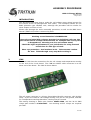
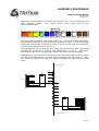
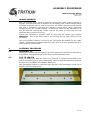
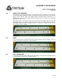
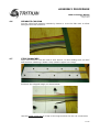
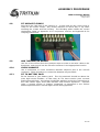
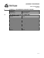
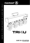
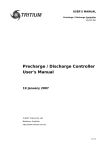
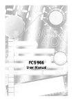
ASSEMBLY PROCEDURE
CMU Cell Sense Wiring
TRI67.006 ver 3
1 August 2012
CMU Cell Sense Wiring
Assembly Procedure
1 August 2012
©2012 Tritium Pty Ltd
Brisbane, Australia
http://www.tritium.com.au
1 of 10
ASSEMBLY PROCEDURE
CMU Cell Sense Wiring
TRI67.006 ver 3
1 August 2012
TABLE OF CONTENTS
1
Introduction........................................................................................3
2
CMU...................................................................................................3
3
Wiring Harness...................................................................................5
4
4.1
4.2
4.3
4.4
4.5
4.6
4.7
4.8
4.9
4.10
4.11
Assembly Procedure............................................................................5
Assembly Jig.......................................................................................................... 5
Cut to length......................................................................................................... 5
Mark for trimming.................................................................................................. 6
Trim....................................................................................................................... 6
Split Branches....................................................................................................... 6
Separate CMU end................................................................................................. 7
Strip Branches....................................................................................................... 7
Fit Microfit crimps.................................................................................................. 8
Add thermistor wiring............................................................................................8
Check harness....................................................................................................... 8
Fit to battery pack................................................................................................. 8
5
5.1
Appendix A – Recommended Component Sources..................................9
CAN cabling & Low Voltage Connectors.................................................................9
6
6.1
Appendix B – Guide to Successful Crimping.........................................10
Molex MicroFit 3.0............................................................................................... 10
7
Revision Record................................................................................10
2 of 10
ASSEMBLY PROCEDURE
CMU Cell Sense Wiring
TRI67.006 ver 3
1 August 2012
1
INTRODUCTION
This document describes how to make the cell voltage sense wiring harness for
the Tritium 8-cell Cell Management Unit (CMU). The examples shown are for
60Ah prismatic type LiFePO4 cells, although the procedure will be similar for
other shapes and sizes of cell.
Please read through the entire assembly procedure, as well as the BMS User's
Manual (TRI67.011) before commencing work.
Working around batteries is DANGEROUS.
Not only are lethal high voltages present, but individual cells can also
put out thousands of amps when shorted, for example with a stray wire
or dropped tool, throwing out arcs and molten metal.
Check the legal requirements in your jurisdiction for using licensed
technicians for this type of work.
Wear eye protection. Use insulated tools. Take extreme caution.
Go slow. Think through every step before doing it.
2
CMU
The 8-cell CMU has the connections for the cell voltage and temperature sensing
at one end of the circuit board. The CAN bus ribbon cable connector is at the
other end of the board. The CMU is shown below:
The cell sense connector is a 12-way 3mm Molex Microfit connector, with locking
ramp. 8 pins are used for cell voltage sensing, one pin for cell ground, and two
for a temperature sensing thermistor, leaving one pin unused.
The mating housing is Molex part number 43645-1200, and the 20-24 AWG
crimps part number is 43030-0007. One housing and 11 crimps are required
per CMU.
3 of 10
ASSEMBLY PROCEDURE
CMU Cell Sense Wiring
TRI67.006 ver 3
1 August 2012
The pinout is shown below, as viewed from the wire side – as you would look at it
while inserting crimps.
The colours shown match those used in the
recommended cable.
(RED)
(ORANGE)
(YELLOW)
(GREEN)
(BLUE)
(PURPLE)
CELL
0+
CELL
2+
CELL
4+
CELL
6+
CELL
7+
CELL
5+
(GREY)
CELL
3+
(WHITE)
(BLACK)
(BROWN)
(BROWN)
CELL
1+
CELL
0–
T+
T–
The CMU senses anywhere from one to eight cells. Cell 0 must always be the first
cell connected with Cell 0– connected to its negative terminal. If one cell is being
monitored, it should be connected to Cell 0; if two are monitored, they should be
connected to Cell 0 and Cell 1, and so on.
The temperature sensor must be electrically isolated from the cells, and would
normally be positioned to monitor the temperature of Cell 0. Gluing the
thermistor to the cell or cell terminal is usually the most convenient option.
Schematically, the connections are shown in the following diagram, which shows
one full 8-cell CMU (CMU 1), and one CMU monitoring four cells (CMU 2). Note
the connection order to the CMU, this is done to simplify the wiring layout in later
steps.
To next positive cell group
Cell 3+
CMU 2
1
2
3
4
5
6
7
8
9
10
11
12
Cell 0+
Cell 2+
Cell 3+
Cell 1+
Cell 2+
Thermistor
Cell 1+
Cell 0+
CMU 2 Cell 0-
Cell 7+
Cell 6+
Cell 5+
Cell 4+
Cell 3+
Cell 2+
Cell 1+
Thermistor
Cell 0+
CMU 1 Cell 0-
Cell 0+
Cell 2+
Cell 4+
Cell 6+
Cell 7+
Cell 5+
Cell 3+
Cell 1+
1
2
3
4
5
6
7
8
9
10
11
12
CMU 1
From nextnegative cell group
4 of 10
ASSEMBLY PROCEDURE
CMU Cell Sense Wiring
TRI67.006 ver 3
1 August 2012
3
WIRING HARNESS
The cell voltage sense harness should be wired with cable rugged enough to
tolerate some abrasion due to vibration in the battery pack, with a voltage rating
of several hundred volts (in case it touches a cell further along the series string)
and with a resistance such that the balance current won't cause significant
changes in the cell voltage reading. It should be small enough diameter to fit
into the microfit housing and crimps, but not too small to crimp into the ring
terminals that connect to the cell.
Tritium has identified a suitable cable as part from Pro Power, part number
05B91510. This is the cable used in the pictures for the next section of this
document.
The ring terminals used to connect to the cell should be suitable for the cable
chosen. Doubling the stripped cable over may bring it up to a suitable size for a
wider selection of terminals.
4
ASSEMBLY PROCEDURE
4.1
ASSEMBLY JIG
Making an assembly jig with bolts at the same spacing as the battery terminals is
a good idea, saving the danger of working around high power cells.
4.2
CUT TO LENGTH
Work out where you want the CMU to be located. It should be fastened to the
wall of the battery box to aid in heatsinking, with the supplied insulation material,
as outlined in the BMS User's Manual TRI67.011.
The appropriate length of cable has been placed on the assembly jig and cut to
length in the following photo:
5 of 10
ASSEMBLY PROCEDURE
CMU Cell Sense Wiring
TRI67.006 ver 3
1 August 2012
4.3
MARK FOR TRIMMING
The reason for choosing the pinout of the voltage sense connector on the CMU is
to make the wiring harness simpler and neater. Each wire branches out from the
edge of the ribbon, with the ribbon being trimmed down narrower as it
approaches Cell 7. The following picture shows the cut points for trimming
marked onto the cable.
The Brown wire is not used, and can be removed completely and used for the
thermistor wiring. The Red wire branches out to Cell 0+, and the Black to Cell 0–.
The White wire to Cell 1+, Orange to Cell 2+, and so on. Each cut will be one
wire deeper into the ribbon.
4.4
TRIM
Cut in on the marks, and then from the marks to the end of the ribbon. The cut
pieces can then be removed, as shown below:
4.5
SPLIT BRANCHES
Cut back along from each mark by one cell length, and split the resulting stub off
in the direction of each cell, as shown below:
6 of 10
ASSEMBLY PROCEDURE
CMU Cell Sense Wiring
TRI67.006 ver 3
1 August 2012
4.6
SEPARATE CMU END
Cut the cable back between strands by 10mm or so at the CMU end, to allow
fitting the microfit connector.
4.7
STRIP BRANCHES
Strip around 10mm from the end of each branch, to allow folding back on itself
and therefore obtaining a better crimp (double copper into crimp).
Fold back the stripped length, as shown below:
Use the proper crimp tool to crimp on the ring terminals for the cell connections.
7 of 10
ASSEMBLY PROCEDURE
CMU Cell Sense Wiring
TRI67.006 ver 3
1 August 2012
4.8
FIT MICROFIT CRIMPS
Strip back the CMU end of the cable by 2 – 2.5mm and use the correct tool to
crimp on the molex crimps. Pay careful attention to which way is 'up' when
orienting the crimps and the housing. The following photo shows the correct
relationship. Refer to Appendix A for component sources and Appendix B for
crimping instructions.
4.9
ADD THERMISTOR WIRING
Use one of the offcuts from the previous steps to make a two-wire cable to the
thermistor, and crimp it into the microfit connector in the appropriate location.
4.10
CHECK HARNESS
Use a multimeter to check resistance between adjacent pins in the microfit
connector. There should be no connection between any terminals.
4.11
FIT TO BATTERY PACK
Fit the harness to your battery pack. The ring terminals should be above the
main high-current busbars, so that they do not have traction pack currents
flowing through them. Use spring or belleville washers so that the connections to
the cells remain tight, even with vibration and thermal expansion. Consider
using a contact grease or jointing compound, as described in the Tritium
Wavesculptor200 user's manual high-current wiring appendix.
8 of 10
ASSEMBLY PROCEDURE
CMU Cell Sense Wiring
TRI67.006 ver 3
1 August 2012
5
APPENDIX A – RECOMMENDED COMPONENT SOURCES
Part Description
5.1
Manufacturer
Manufacturer Part Number
Suggested Supplier
Supplier Part Number
CAN CABLING & LOW VOLTAGE CONNECTORS
DeviceNet Cable (per metre)
Lapp Cable
2170343
Element 14
161-7915
MicroFit crimps (20-24 AWG)
Molex
43030-0007
Element 14
973-3027
12 way MicroFit connector housing (Cell wiring)
Molex
43645-1200
Element 14
192-4578
10 way 24 AWG cell ribbon cable (Cell wiring)
Pro Power
05B91510
Element 14
150-434
9 of 10
ASSEMBLY PROCEDURE
CMU Cell Sense Wiring
TRI67.006 ver 3
1 August 2012
6
APPENDIX B – GUIDE TO SUCCESSFUL CRIMPING
6.1
MOLEX MICROFIT 3.0
A dedicated MicroFit hand tool such as Molex part number 63819-0000 is the
correct tool for the job. This tool is available from Digikey, part WM9022-ND.
This tool provides far superior results compared to the generic crimp tool and will
result in the most reliable and safe installation.
At the bare minimum, use a quality hand crimp tool such as Molex part number
0638111000, available at a reasonable price from Digikey, part WM9999-ND.
The tool must be shaped to fold the crimp ears around and down through the
centre of the wire conductor bundle – crimping with pliers or an 'automotive'
barrel type crimp tool will not give a satisfactory result.
Refer to the Molex “Quality Crimping Handbook”:
http://www.molex.com/pdm_docs/ats/TM-638000029.pdf
Note the pictures in the “Troubleshooting” section for the visual differences
between a good and a bad crimp.
7
REVISION RECORD
REV
DATE
CHANGE
1
20 May 2011
Document creation (JMK)
2
15 March 2012
Updated for 250mA BMS nodes
3
1 August 2012
Updated to match BMS User's Manual
10 of 10