1
Maintenance Manual
tm
Extensa 450 Series
Notebook Computers
9805725-0001
November 1995
Copyright (©) 1995 Texas Instruments Incorporated
All Rights Reserved — Printed in U.S.A.
Extensa 450 Series Notebook Computers
Maintenance Manual
TI Part No. 9805725-0001
Original Issue: November 1995
Changes may be made periodically to the information in this publication.
Such changes will be incorporated in new editions of this manual.
No part of this publication may be reproduced, stored in a retrieval system,
or transmitted, in any form or by any means, electronic, mechanical,
photocopy, recording, or otherwise, without the prior written permission of
Texas Instruments Incorporated.
The equipment, as well as the programs that TI has created to use with
them, are tools that can help people better manage the information used in
their business; but tools — including TI products — cannot replace sound
judgement nor make the manager’s business decisions.
Consequently, TI cannot warrant that its products are suitable for any
specific customer application. The manager must rely on judgement of what
is best for his or her business.
Address all correspondence regarding orders to:
Texas Instruments Incorporated
P.O. Box 6102, M/S 3255
Temple, Texas 76503
Extensa 450, TravelMate, 5000, 4000M, 4000E, 4000 and BatteryPro are trademarks of Texas Instruments Incorporated. The icons in the Windows Notebook and
Startup groups are copyrighted by Texas Instruments Incorporated.
BitCom and BitFax are trademarks of BIT Software, Inc.
Hayes is a registered trademark and SmartModem2400 is a trademark of Hayes MicroComputer Products Inc.
IBM, OS/2, AT PS/2, and VGA are trademarks of International Business Machines
Corporation.
Intel, and IntelDX4 are trademarks of Intel Corporation
Lotus is a trademark of Lotus Development Corporation
MNP is a registered trademark and Microcom is trademark of Microcom Inc.
Microsoft and Windows 95 are trade marks of Microsoft Corporation.
Ethernet is a registered trademark of Xerox Corporation.
NetWare is a registered trademark of Novell, Inc.
UNIX is a registered trademark of American Telephone and Telegraph.
SimulSCAN is a trademark of Cirrus Logic, Inc.
Contents
Preface
Section 1 General Description
1.1 Introduction. . . . . . . . . . . . . . . . . . . . . . . . . . . . . . . . . . . . 1-1
1.2 Product Models . . . . . . . . . . . . . . . . . . . . . . . . . . . . . . . . . 1-2
1.3 International Product Versions. . . . . . . . . . . . . . . . . . . . . . 1-2
1.4 Product Overview . . . . . . . . . . . . . . . . . . . . . . . . . . . . . . . . 1-3
1.4.1 External Ports . . . . . . . . . . . . . . . . . . . . . . . . . . . . . . 1-5
1.4.2 Touchpad Pointing Device . . . . . . . . . . . . . . . . . . . . . 1-6
1.4.3 Keyboard . . . . . . . . . . . . . . . . . . . . . . . . . . . . . . . . . 1-6
1.4.4 Standard Power Features. . . . . . . . . . . . . . . . . . . . . . 1-8
1.4.5 Wireless Connection With Serial Infrared Port . . . . . . 1-9
1.4.6 Preloaded Software . . . . . . . . . . . . . . . . . . . . . . . . . . 1-9
1.4.7 Notebook Expansion Capabilities . . . . . . . . . . . . . . . . 1-9
1.5 Standard Test Features . . . . . . . . . . . . . . . . . . . . . . . . . . . 1-10
1.6 Notebook Assemblies and Subassemblies. . . . . . . . . . . . . . 1-10
1.6.1 Cover-Display Assembly . . . . . . . . . . . . . . . . . . . . . . 1-11
1.6.2 System Base Assembly . . . . . . . . . . . . . . . . . . . . . . . 1-11
1.7 Extensa 450 Series Notebook Specifications. . . . . . . . . . . . 1-12
1.8 Agency Approvals. . . . . . . . . . . . . . . . . . . . . . . . . . . . . . . . 1-13
Section 2
Installation
2.1 Introduction. . . . . . . . . . . . . . . . . . . . . . . . . . . . . . . . . . . . 2-1
2.2 Unpacking Instructions . . . . . . . . . . . . . . . . . . . . . . . . . . . 2-1
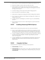
2.3 Installing Notebook Options . . . . . . . . . . . . . . . . . . . . . . . 2-1
2.3.1 Installing Dual Inline Memory Module(s) . . . . . . . . . . 2-1
2.3.2 Installing PCMCIA Options. . . . . . . . . . . . . . . . . . . . . 2-3
2.3.3 Installing the Port Adapter . . . . . . . . . . . . . . . . . . . . 2-4
2.3.4 Installing the Optional Numeric Keypad . . . . . . . . . . 2-5
2.4 Installing the Battery Pack(s ) . . . . . . . . . . . . . . . . . . . . . . . 2-5
2.5 Installing External Devices . . . . . . . . . . . . . . . . . . . . . . . . . 2-6
Contents iii
2.5.1 Installing an External Keyboard/Mouse . . . . . . . . . . . 2-6
2.5.2 Installing External Parallel Printer . . . . . . . . . . . . . . . 2-8
2.5.3 Installing External Serial Port Device . . . . . . . . . . . . . 2-8
2.5.4 Installing External VGA Monitor . . . . . . . . . . . . . . . . . 2-10
2.5.5 Installing SIR Devices . . . . . . . . . . . . . . . . . . . . . . . . . 2-10
2.6 Installing the AC Power Adapter
. . . . . . . . . . . . . . . . . . . . 2-11
2.7 Initial System Checkout . . . . . . . . . . . . . . . . . . . . . . . . . . . 2-12
2.8 Configuring the System. . . . . . . . . . . . . . . . . . . . . . . . . . . . 2-12
2.9 Making Backups of System Software. . . . . . . . . . . . . . . . . . 2-13
2.10 Loading Application Software . . . . . . . . . . . . . . . . . . . . . . 2-13
Section 3 Operating Instructions
3.1 Introduction . . . . . . . . . . . . . . . . . . . . . . . . . . . . . . . . . . . . 3-1
3.2 Notebook Controls and Indicators . . . . . . . . . . . . . . . . . . . . 3-1
3.2.1 LCD Brightness Control . . . . . . . . . . . . . . . . . . . . . . . 3-2
3.2.2 Button Switches . . . . . . . . . . . . . . . . . . . . . . . . . . . . . 3-2
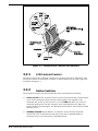
3.2.3 Cover Release Latch . . . . . . . . . . . . . . . . . . . . . . . . . . 3-3
3.2.4 Touch Pad Controls . . . . . . . . . . . . . . . . . . . . . . . . . . 3-3
3.2.5 Keyboard Mode LEDs. . . . . . . . . . . . . . . . . . . . . . . . . 3-3
3.3 Operating Procedures . . . . . . . . . . . . . . . . . . . . . . . . . . . . 3-3
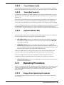
3.3.1 Floppy Drive Operating Procedures . . . . . . . . . . . . . . 3-4
3.3.2 Installing/Removing PCMCIA Options . . . . . . . . . . . . 3-4
3.3.3 Computer Hot Keys . . . . . . . . . . . . . . . . . . . . . . . . . . 3-5
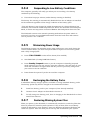
3.3.4 Responding to Low Battery Conditions. . . . . . . . . . . . 3-5
3.3.5 Minimizing Power Usage . . . . . . . . . . . . . . . . . . . . . . 3-5
3.3.6 Recharging the Battery Packs . . . . . . . . . . . . . . . . . . 3-6
3.3.7 Restoring Missing System Files . . . . . . . . . . . . . . . . . 3-6
3.3.8 Rebuilding the System Software. . . . . . . . . . . . . . . . . 3-6
Section 4
Theory of Operation
4.1 Introduction . . . . . . . . . . . . . . . . . . . . . . . . . . . . . . . . . . . . 4-1
4.2 Notebook Functional Description . . . . . . . . . . . . . . . . . . . . 4-1
4.2.1 Processor/Memory Subsystems . . . . . . . . . . . . . . . . 4-1
4.2.2 I/O Subsystem . . . . . . . . . . . . . . . . . . . . . . . . . . . . . 4-6
4.2.3 Video Subsystem . . . . . . . . . . . . . . . . . . . . . . . . . . . . 4-7
iv Contents
4.2.4 Hard Disk Subsystem . . . . . . . . . . . . . . . . . . . . . . . . 4-8
4.2.5 Floppy Diskette Drive Subsystem. . . . . . . . . . . . . . . . 4-9
4.2.6 PCMCIA Subsystem . . . . . . . . . . . . . . . . . . . . . . . . . . 4-9
4.2.7 Power Subsystem. . . . . . . . . . . . . . . . . . . . . . . . . . . . 4-10
Section 5 Troubleshooting Procedures
5.1 General . . . . . . . . . . . . . . . . . . . . . . . . . . . . . . . . . . . . . . . 5-1
5.2 Overview of Fault Isolation Process . . . . . . . . . . . . . . . . . . 5-1
5.3 Troubleshooting Procedures. . . . . . . . . . . . . . . . . . . . . . . . 5-3
5.3.1 Troubleshooting a Power Supply Problem . . . . . . . . . 5-3
5.3.2 Troubleshooting a Display Problem . . . . . . . . . . . . . . 5-5
5.3.3 Fault Isolation Using Selftest . . . . . . . . . . . . . . . . . . . 5-5
5.3.4 PCMCIA Modem Problems. . . . . . . . . . . . . . . . . . . . . . 5-5
5.3.5 Fault Isolation Using Diagnostics . . . . . . . . . . . . . . . . 5-6
Section 6 Field Service
6.1 Introduction . . . . . . . . . . . . . . . . . . . . . . . . . . . . . . . . . . . . 6-1
6.2 Preventive Maintenance . . . . . . . . . . . . . . . . . . . . . . . . . . . 6-1
6.2.1 Cleaning the Computer . . . . . . . . . . . . . . . . . . . . . . . 6-1
6.2.2 Protecting the Disk Drives . . . . . . . . . . . . . . . . . . . . . 6-2
6.2.3 Handling the Computer Battery Pack. . . . . . . . . . . . . 6-2
6.2.4 Restoring System Software. . . . . . . . . . . . . . . . . . . . . 6-2
6.3 Required Tools and Equipment . . . . . . . . . . . . . . . . . . . . . 6-3
6.4 Notebook Field-Replaceable Parts and Assemblies. . . . . . . . 6-3
6.4.1 Cover-Display Assembly . . . . . . . . . . . . . . . . . . . . . . 6-3
6.4.2 System Base Assembly . . . . . . . . . . . . . . . . . . . . . . . 6-4
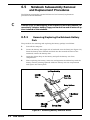
6.5 FRU Removal and Replacement Procedures . . . . . . . . . . . . 6-6
6.5.1 Removing/Replacing the Notebook Battery Pack . . . . . 6-6
6.5.2 Removing/Replacing PCMCIA Options . . . . . . . . . . . . 6-7
6.5.3 Removing/Replacing the Floppy Drive . . . . . . . . . . . . 6-7
6.5.4 Removing/Replacing the Hard Drive . . . . . . . . . . . . . 6-7
6.5.5 Removing/Replacing the Keyboard Assembly . . . . . . . 6-8
6.5.6 Removing/Replacing the Heat Sink . . . . . . . . . . . . . . 6-8
6.5.7 Removing/Replacing Memory Modules (DIMMS) . . . . 6-9
6.5.8 Removing and Replacing the Cover-Display Assembly 6-10
Contents v
6.5.9 Removing and Replacing the Inverter Board. . . . . . . . 6-10
6.5.10 Opening/Replacing the Top Case Assembly . . . . . . . 6-11
6.5.11 Removing/Replacing the Touch Pad Assembly . . . . . 6-11
6.5.12 Removing/Replacing the SIR Board . . . . . . . . . . . . . 6-13
6.5.13 Removing/Replacing the Primary Battery Board . . . 6-14
6.5.14 Removing/Replacing Power Supply Board . . . . . . . . 6-15
6.5.15 Removing/Replacing the Memory Board . . . . . . . . . 6-16
6.5.16 Removing/Replacing the Main Board . . . . . . . . . . . . 6-16
6.5.17 Removing/Replacing the Secondary Battery Board . 6-18
Appendix A
Self-Test Error Messages
A.1 Introduction . . . . . . . . . . . . . . . . . . . . . . . . . . . . . . A-1
Appendix B
Connector Pinouts
B.1 Introduction . . . . . . . . . . . . . . . . . . . . . . . . . . . . . . . . . . . B-1
Appendix C
PC-Doctor Diagnostics
C.1 Introduction . . . . . . . . . . . . . . . . . . . . . . . . . . . . . . . . . . . C-1
C.2 Starting PC-Doctor . . . . . . . . . . . . . . . . . . . . . . . . . . . . . . C-1
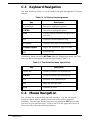
C.3 Keyboard Navigation . . . . . . . . . . . . . . . . . . . . . . . . . . . . . C-2
C.4 Mouse Navigation . . . . . . . . . . . . . . . . . . . . . . . . . . . . . . . C-2
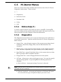
C.5 PC-Doctor Menus . . . . . . . . . . . . . . . . . . . . . . . . . . . . . . . C-3
C.5.1 Online Help (?). . . . . . . . . . . . . . . . . . . . . . . . . . . . . . C-3
C.5.2 Diagnostics . . . . . . . . . . . . . . . . . . . . . . . . . . . . . . . . C-3
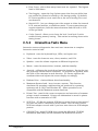
C.5.3 Interactive Tests Menu . . . . . . . . . . . . . . . . . . . . . . . C-4
C.5.4 Hardware Info Menu . . . . . . . . . . . . . . . . . . . . . . . . . C-5
C.5.5 Utility Menu . . . . . . . . . . . . . . . . . . . . . . . . . . . . . . . C-5
C.6 Quitting PC-Doctor . . . . . . . . . . . . . . . . . . . . . . . . . . . . . . C-6
C.7 Remote Operation . . . . . . . . . . . . . . . . . . . . . . . . . . . . . . . C-6
vi Contents
Preface
This manual provides installation, operation and servicing data for the
Extensatm 450 Series Notebook Computers.
Intended Audience
This manual is primarily intended for use by qualified service technicians
but contains information useful to non-technical users.
Contents
This manual contains six sections and multiple reference appendices
including:
•
•
•
•
•
•
n
Section 1: General Description — Introduces the main features of the
notebook; provides a list of physical and electrical specifications.
Section 2: Installation — Describes how to unpack, install options
and cable up the notebook computer in a desktop environment.
Section 3: Operating Instructions — Describes the notebook
operating controls and indicators and modes of operation.
Section 4: Theory of Operation — Describes detailed theory of
operation for Extensa series notebooks.
Section 5: Troubleshooting — Provides troubleshooting procedures
for the Extensa 450 series notebooks.
Section 6: Field Service — Provides corrective maintenance
procedures for the notebook computer.
•
Appendix A: Self Test Error Messages
•
Appendix B: Connector Pinouts
•
Appendix C: PC-Doctor Reference Data
Note: Additional appendices will be added at a future date to document
new members of the Extensa product family.
Other Manuals About the System
The following documents provide additional information related to the
Extensa 450 series:
Preface vii
•
Extensa 450 Series Notebook Computer User’s Reference Manual,
Part No. 9803942-0001; contains reference information regarding the
Extensa 450 series software including the TI custom utilities.
•
Windows 95 Help (online)
•
PC-Doctor Help and Technical Reference (online)
Ordering Parts and Supplies
To order a copy of any TI publication or to order option kits, spare parts or
supplies for your system, contact your TI Reseller or:
Telephone Toll-free: 1-800-TI TEXAS
viii Preface
Section 1
General Description
1.1
Introduction
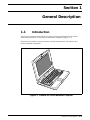
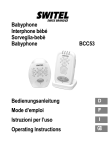
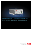
This manual contains field and factory level servicing information for the Texas
Instruments Extensa tm 450 Series of Notebook Computers (Figure 1-1).
This section provides a general overview and specifications for the Extensa 450
Series Notebook Computers.
Figure1-1 Extensa 450 Series Notebook Computer
General Description 1-1
1.2
Product Models
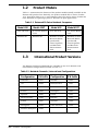
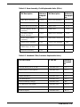
Table 1-1 summarizes the features of the product models initially available in the
Extensa 450 product line. Basically, the product models offer a choice of either
10.4" Dual Scan Color or 9.4" Active Matrix Color LCDs and a choice of either the
basic Windows 95 operating system or Windows 95 plus applications.
Table 1-1 Extensa 450 Series Notebook Computers
Model 450
Model 450T
10.4" DS LCD
9.4" Active Matrix
Color
10.4" DS LCD
9.4" Active Matrix
Color
Windows 95
Windows 95
Windows 95 Plus
Microsoft Works,
Quicken SE,
Lotus Organizer,
and Microsoft
Entertainment
Pack
Windows 95 Plus
Microsoft Works,
Quicken SE,
Lotus Organizer,
and Microsoft
Entertainment
Pack
1.3
Model 455
Model 455T
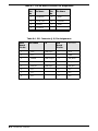
International Product Versions
The Extensa 450 Series Notebooks are available in one of 15 domestic and
international configurations as listed in Table 1-2.
Table 1-2. Notebook Domestic/International Configurations
Configuration
1-2
P/N Suffix
Configuration
P/N Suffix
Domestic
-0001
Swedish
-0010
UK
-0002
Swiss/French
-0011
German
-0003
Danish
-0012
French
-0004
Norwegian
-0013
Spanish
-0005
Finish
-0014
Swiss/German
-0006
Belgium
-0015
Italian
-0007
Austrian
-0016
Portuguese
-0008
Latin American
-0018
Western European
-0009
General Description
1.4
Product Overview
All members of the Extensa 450 Series are high performance notebooks powered by
the 75MHz IntelDX4 processor and Windows 95 tm Operating System software.
As a standard feature, all members of the Extensa 450 family also contain the
following features:
•
4MB of RAM memory (user-expandable to 32MB)
•
128 bytes of battery-backed up CMOS RAM
•
512 KB of video RAM
•
340 Million Byte Hard Drive (user replaceable)
•
•
•
•
•
•
•
•
•
Support for one PCMCIA Type I or II option (Type III if floppy drive is removed
with option)
Ergonomic keyboard with palm rest (2.7 mm travel); built-in touchpad pointing
device
Most standard external device interfaces including serial, parallel, PS/2,
external VGA, and serial infrared wireless port
Removable 3.5", 1.44 MB Floppy Drive (second Lithium Ion battery or a type III
PCMCIA device can be installed in its place with option)
Choice of LCD displays (10.4" Dual Scan Color or 9.4" Active Matrix Color
LCD).
AC Adapter with autosensing (100 VAC to 240 VAC, 50 to 60 Hz); 34 Watts of
DC output power
10.8 Volt, 2400 mAH capacity, Nickel-Metal Hydride (NiMH) primary battery
pack
Provisions for secondary 10.8V, 1460 mAH capacity, Lithium-Ion Battery Pack
(with removal of Floppy Drive)
Power management features for longer portable operation away from AC power.
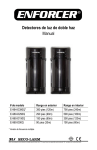
General Description 1-3
Figure 1-2 Extensa 450 Series Features
1-4
General Description
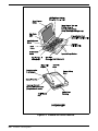
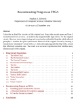
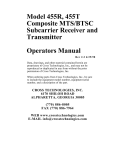
1.4.1
External Ports
As shown in Figure 1-3, the notebook computer contains the following external
ports:
•
Serial Infrared (SIR) Port for wireless connection with a similarly equipped
printer or computer
•
9-Pin Serial Port for attaching any RS-232 type serial device to the Notebook
•
15-Pin External VGA Monitor Port for attaching an external monitor
•
6-Pin PS/2 Port to attach an external Keyboard or Mouse
•
Second 6-Pin PS/2 Port for attaching an external Keyboard/Mouse
•
AC Adapter Connector for attaching the AC Adapter to the notebook
Figure 1-3 Notebook External Ports
General Description 1-5
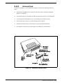
1.4.2
Touchpad Pointing Device
All members of the Extensa family feature a built-in Touchpad pointing device
located near the center of the keyboard’s palmrest. With light presure, the cursor
can quickly be positioned to the desired point; a quick double tap on the Touchpad
and you have selected an object. Two select buttons (switches) are located along the
front edge of the notebook
.
Figure1-4 Extensa Touchpad
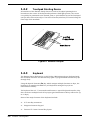
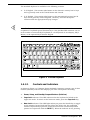
1.4.3
Keyboard
The Extensa Series Keyboard is an 83/84-key, IBM enhanced-type keyboard with
the standard character and function keys plus 12 programmable function keys (F1
through F12).
Using the Special Function (Fn) key which assigns multiple functions to keys, the
keyboard can emulate the IBM 101/102 keyboards using 83 keys (84 on
international models).
The keyboard has a 2.77 mm stroke and features a special keyboard interface chip
that can detect multiple levels of key input (good simulation of N-key rollover for up
to 10 keys).
Some of the major features of the keyboard include:
1-6
•
2.77-mm Key movement
•
Integrated numeric keypad
•
“Inverted T" Cursor Control Key layout
General Description
The notebook keyboard is available in the following versions:
•
•
n
U.S. English - This version (also known as the domestic version) has 81 keys
and is generally used in the United States and Canada.
U.K. English - This version (also known as the international version) has 82
keys and is generally used in England, Germany, and other European
countries with the appropriate keycap changes.
Note: The Extensa Series Notebook Computer User’s Reference Manual contains descriptions of keyboard special function keys. A six-pin Mini-DIN connector can attach to either an external PS/2 keyboard (or 101 Keyboard via an adapter), PS/2
Mouse, or the optional PS/2 Numeric Keypad.
Esc
F1
@
2
1
F4
F3
F2
F5
3
F7
%
4
W
Q
F6
F9
&
^6
5
E
F8
8
Y
T
A
Shift
S
Z
F
D
X
C
G
U
V
H
B
N
Ctrl
F12
Break
NumLk
Prt Sc
ScrLk
SysRq
P
O
5
Delete
{
}
[
]
6
J
K
L
1
2
3
Enter
Shift
M
Alt
Insert
0
I
0
Fn
Pause
9
4
Caps
Lock
F11
9
8
7
7
R
F10
0
Alt
Home
End
P g Up
P gDn
Figure1-5 Extensa Keyboard
1.4.3.1
Controls and Indicators
As shown in Figure 1-6, Extensa Series Notebook Computers contain a set of three
buttons (switches) and five LED displays just above the keyboard including:
•
•
•
Power, Setup, and Standby/Suspend Buttons (Switches)
Caps Lock indicator. This LED indicates that the keyboard is locked in the
uppercase mode. To switch to the lowercase mode, press the Caps Lock key.
Num Lock indicator. This LED lights when you press the NumLk key to toggle
on the numeric keypad lock function. When the LED is On, the embedded
numeric keyboard keys generate AT-keypad characters and functions when
pressed in conjunction with the Shift key. When the indicator is Off, pressing
General Description 1-7
the Fn key with the appropriate keys provides cursor movement, paging and
other functions in the normal mode.
•
•
•
Scroll Lock indicator. This LED lights to indicate that the keyboard is locked
in the scroll mode.
Hard Disk Drive Activity Indicator. Indicates when notebook is accessing the
hard drive.
Standby Indicator. Lights when Notebook is in Standby mode.
Figure1-6 Extensa Series Controls and Indicators
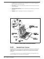
1.4.4
Standard Power Features
Notebook power for the Extensa 450 Series Notebook Computers is provided by an
AC Adapter and a rechargeable 10.8 V, 2400 mAh Duracell nickel metal hydride
(NiMH) battery pack that installs in a power bay near the front of the notebook
(right side).
A second lithium ion battery may optionally be installed in the Floppy Drive bay
when the Floppy Drive is removed from the Notebook.
1-8
General Description
All members of the Extensa 450 family feature TI’s patented power management
subsystem (hardware and software) that provides longer portable operation and
protection of files during low battery conditions.
1.4.5
Wireless Connection With Serial Infrared Port
The Extensa series notebooks are equipped with a Serial Infrared (IR) port that
offers wireless communication with a variety of IRDA-compliant devices made by
other manufacturers.
n
Note: Prior to communicating with an external device equipped with a serial infrared interface, the appropriate third-party drivers must be installed on your notebook.
1.4.6
Preloaded Software
All members of the Extensa 450 Notebook family are preloaded with the Windows
95 Operating System. In addition, Extensa Models 455 and 455T come standard
with the following application packages installed:
•
Microsoft Works
•
Quicken SE
•
Lotus Organizer
•
Microsoft Entertainment Pack No. 4
1.4.7
Notebook Expansion Capabilities
Expansion capabilities built into the Extensa notebook series include:
•
•
•
•
•
User installable expansion RAM memory (to a maximum of 32 MB)
By removing the floppy drive, you can add either a second battery pack or a
Type III PCMCIA device with option.
A Cable Connect PS/2 Numeric Keypad option, P/N 2581381-0001, can be
attached to either of the two external PS/2 Ports.
A parallel device can be attached to the notebook’s external 25-pin parallel port
(EPP/ECP compatible).
With the port adapter installed (supplied with the notebook), the notebook’s
expansion bus is adapted to provide the following external ports:
–
Serial RS-232 Port for attaching any serial device
–
External VGA Port for driving an external color monitor
–
Second PS/2 Port for attaching an external keyboard or mouse
General Description 1-9
•
Third Party External PS/2 keyboard (or external mouse)
1.5
Standard Test Features
The Extensa Series Notebook Computers use modular design and built-in test
features to reduce the mean time to repair. A power on self-test automatically
verifies the operational state of the primary circuits and a powerful suite of
diagnostic tests are available to further test selected parts of the system.
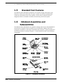
1.6
Notebook Assemblies and
Subassemblies
The Extensa Series Notebooks are modular in design and can be disassembled for
maintenance purposes using a standard set of flat-bladed, Phillips-head and
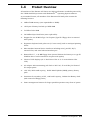
hexagonal screwdrivers. The major assemblies that comprise a typical notebook in
the Extensa family are shown in Figure 1-7 and briefly described in the following
paragraphs.
Figure 1-7 Notebook Assemblies
1-10
General Description
1.6.1
Cover-Display Assembly
The Cover-Display Assembly contains the LCD screen and associated high voltage
power supply and video circuitry. The Cover-Display Assembly contains three
field-replaceable components including:
•
LCD Assembly
•
Inverter Board
•
Slide Pot/Converter Board
The Cover-Display Assembly attaches to the System Base Assembly through four
top mounted screws and six mounting screws on the bottom of the computer.
1.6.2
System Base Assembly
As shown in Figure 1-7, the majority of the notebook’s field replaceable units (FRUs)
are located in the system base assembly. These FRUs include:
•
Main Board Assembly
•
Hard Disk Drive Assembly
•
Memory Board Assembly
•
Up to two Dual Inline Memory Modules
•
Serial Infra-red Board Assembly
•
Floppy Drive Assembly
•
Secondary Battery Board Assembly
•
Power Supply Board Assembly
•
Battery Pack Assembly
•
Top Case Assembly
•
Touchpad Assembly
•
Keyboard Assembly (removed in Figure 1-7 for clarity)
•
Battery Board Assembly
General Description 1-11
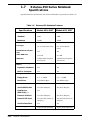
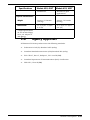
1.7
Extensa 450 Series Notebook
Specifications
Specifications for the Extensa 450 Series Notebooks are provided in Table 1-6.
Table 1-6
Specifications
Extensa 450 Notebook Features
Models 450/450T
Models 455/455T
Memory:
Standard:
4MB
4MB
Maximum
32MB
32MB
LCD Type:
10.4" Dual Scan Color
9.4" Active Matrix
Color
Simultaneous LCD/Ext.
VGA
Yes
Yes
Video RAM Size:
512 KB
512 KB
Video Bus
VLBUS with Graphics
Accelerator
VLBUS with Graphics
Accelerator
Ergonomic Keyboard
Yes
Yes
Built-In Touchpad
Yes
Yes
Floppy Drive:
3.5", 1.44MB
3.5", 1.44MB
Hard Drive:
340 Million Byte
340 Million Byte
Serial (RS232) Port
Yes (Port Adapter)
Yes (Port Adapter)
Parallel Port
(EPP/ECP), Yes
Yes
External VGA Port
Yes (Port Adapter)
Yes (Port Adapter)
External PS2 Ports
Yes (2nd PS/2 Port on
Adapter)
Yes (2nd PS/2 Port on
Adapter)
Serial Infrared Port
Yes
Yes
Type I/II (III Optional)
Type I/II (III Optional)
Display
Keyboard/Pointing
Device,
Storage
Interfaces
PCMCIA Support
1-12
General Description
Specifications
Models 450/450T
Software
Models 455/455T
Windows 95
Windows 95,plus
applications
Weight:
Approx. 5.0 Pounds
(2.27kg) *
Approx. 5.0 Pounds
(2.27kg)
Dimensions:
11.7” (L) X 1.7” (H) X
8.2” (W)
11.7” (L) X 1.7” (H) X
8.2” (W)
Physical Characteristics
* Wight specifications
do not include Floppy
Drive, AC Adapter or
2nd Battery
1.8
Agency Approvals
All Extensa 450 Series products meet the following standards:
•
Underwriter’s Lab (UL) Standard 1950 (safety)
•
Canadian Standards Association (CSA) Standard 220 (safety)
•
FCC CFR 47, Part 15, Subpart J, FCC Level B (EMI)
•
Canadian Department of Communications (DOC) Certification
•
VDE 0871, Class B (EMI)
General Description 1-13
2
Installation
2.1
Introduction
This section contains unpacking and preparation for use instructions for the
Extensa 450 Series Notebook Computers.
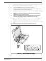
2.2
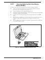
Unpacking Instructions
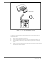
The packaging diagram for the notebook computer is shown in Figure 2-1. Unpack
the computer using the following instructions:
1. Carefully cut the tape that seals the top flap of the shipping carton.
2. Remove the computer and the accessories from the main shipping carton.
3. Remove all protective coverings from the computer.
4. Remove the holding tape and open up the accessory box; remove the contents.
n
Note: Save the shipping containers and packaging for later reuse.
2.3
Installing Notebook Options
If you have no options to install at this time, skip to Paragraph 2.3. Otherwise,
continue with Paragraph 2.2.1.
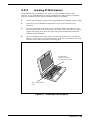
2.3.1
n
c
Installing Dual Inline Memory Module(s)
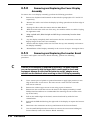
Note: If not installing RAM Expansion option at this time, skip to the next paragraph.
Caution: The Dual Inline Memory Module contains components that are
sensitive to static electricity. When handling the module and the internal parts of the computer, protect against static electricity by using
wrist or ankle grounding straps and grounded working mats. When moving or storing items, use the anti-static bags supplied with the items.
Installation 2-1
1.
Ensure that the notebook is powered off and that the AC Adapter and internal
battery pack(s) is (are) removed from the notebook.
2.
Remove the DIMM module(s) from its shipping container.
3.
Release the Keyboard by pulling the keyboard release tabs forward (tabs are
located underneath the Ctrl and right arrow keys).
4
Disengage the Keyboard using a straight blade screwdrive and gently lifting up
along the front edge of the keyboard.
5
Using the back edge of the keyboard as a hinge, lift the front edge of the
keyboard up and lay it against the display.
6.
Remove the two Phillips head screws holding heatsink to the Main Board
and remove the heatsink by lifting it upwards and out of the unit.
7.
Insert the edge of the DIMM Board into the rear of either available connector
(see Figure 2-1). Use a rocking motion to fully insert the module. Push
downwards on each side of the DIMMs module until it snaps in place.
8.
Replace the heatsink, keyboard assembly and any other components removed in
step 1.
This completes the expansion memory module installation procedure.
Figure 2-1
2-2 Installation
Installing Additional Memory
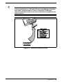
2.3.2
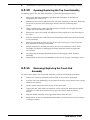
Installing PCMCIA Options
The Notebook has provisions for one Type I or Type II PCMCIA option card.
However, a type III PCMCIA device can be installed if the Floppy Drive is removed
from the notebook and the optional PCMCIA Module is installed..
1.
Review the installation instructions supplied with the PCMCIA option card(s).
2.
Open the Type I/II PCMCIA compartment cover on the left side of the
notebook.
3.
To insert a PCMCIA card, align the card with the socket and slide the card
into the socket until it locks into place. To install a Type III option, you must
remove the Floppy Drive from the right side of the notebookand install the
PCMCIA Option Assembly..
4.
To eject a PCMCIA card, first ensure that the notebook is not accessing the
memory card or device. Under Windows 95, go to the Control Panel, PC Card
and direct the card to stop before removing card.
Type III PCMCIA
If Floppy Drive Removed
and PCMCIA Option installed
Type 1 or Type II PCMCIA
Option
Figure 2-2
Installing PCMCIA Options
Installation 2-3
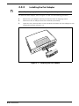
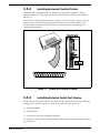
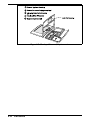
2.3.3
n
Installing the Port Adapter
Note: Skip this paragraph if not installing the Port Adapter at this time.
To install the Port Adapter, refer to Figure 2-3 and use the following procedure:
1
Remove the -port adapter and any accessories from its shipping carton .
2
Disconnect the AC Adapter from the notebook (if attached).
3
Open the rear connector door on the notebook and attach the Port Adapter to the
notebook as shown in Figure 2-3.
Figure 2-3
2-4 Installation
Installing the Port Adapter
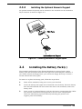
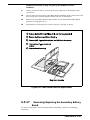
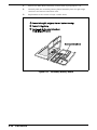
2.3.4
Installing the Optional Numeric Keypad
An optional numeric keyboard can be attached to the notebook via the notebook’s
PS/2 connector as shown in Figure 2-4.
Figure 2-4
2.4
Installing the Numeric Keypad option
Installing the Battery Pack(s )
The standard configuration of the Extensa Notebook is equipped with a single
battery pack that is inserted from the front right side of the computer. However, if
you can do without the Floppy Drive, you can use the floppy drive bay to house a
second Lithium Ion battery pack.
To remove or replace the battery pack, follow the steps below.
1.
Power off the notebook, being sure to save your data first.
2.
Locate the battery door (right side of notebook near the front). Press the battery
door inwards and slide the door toward the front of the notebook; remove the
battery door.
3.
Insert a new or recharged battery pack into the battery compartment bay. Make
sure that the contacts are facing up and to the rear of the compartment.
Check the label (facing up when inserted) indicating the positive and
negative poles of the battery.
Installation 2-5
c
Caution: There is danger of explosion if the battery is incorrectly replaced. Replace the battery only with the same or an equivalent type
recommended by the manufacturer. Discard used batteries according to
the manufacturer’s instructions.
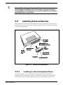
2.5
Installing External Devices
Most external devices connect to the Notebook via the connectors on the rear of the
notebook and on the rear of the Port Adapter supplied with the notebook (see Figure
2-5 for port assignments).
Figure 2-5
2.5.1
Extensa Port Assignments
Installing an External Keyboard/Mouse
As shown in Figure 2-6, the notebook has provisions for two external PS/2
compatible devices (keyboard, mouse, etc.) that may be attached to the notebook.
The pinouts for the 6-pin Mini-DIN connectors are also provided in Figure 2-6.
2-6 Installation
PS/2 Ports
Figure 2-6
PS/2 Port Assignments/Pinouts
To install an external keyboard or external PS/2 mouse on the notebook, use the
following procedure:
1.
Ensure that the notebook is powered off.
2.
Locate the external PS/2 ports at the rear of the notebook (see Figure 2-6).
3.
Attach the PS/2 cable from your mouse and/or keyboard cable to the PS/2
port(s).
4.
Power on any other peripheral devices you may have connected to the notebook,
and then power up the notebook.
Installation 2-7
2.5.2
Installing External Parallel Printer
The Notebook is equipped with a bi-directional, ECC/EPP compatible, 25-pin
parallel printer port. The connector pinouts and connector location are shown in
Figure 2-7.
If you will be using a parallel interface, connect the 25-pin male connector of your
printer cable to the 25-pin female parallel port on your notebook. Refer to the
manual which accompanied your printer for instructions on configuring your
operating environment
Figure 2-7
2.5.3
Parallel Port Location/Pinouts
Installing External Serial Port Device
The notebook contains an RS-232 serial port with a male DB-9 connector as shown
in Figure 2-8. The serial ports are used to interconnect such devices as:
•
External Modem
•
Serial Printer
•
Any device that uses an RS-232 interface
To connect a printer to the notebook, ensure that both the notebook and the printer
are turned off.
2-8 Installation
c
Caution: Never connect a parallel device to a serial port or a serial device to a parallel port or video port; this may cause damage to the Notebook and/or peripheral device. If you are uncertain of what type
connector the external device has, refer to the technical manual for the
external device.
Figure 2-8
Serial Port Location/Pinouts
Installation 2-9
2.5.4
Installing External VGA Monitor
The notebook is capable of driving both its internal LCD display and an external
VGA monitor (LCD only, simultaneous, or VGA only). The external monitor
connector pinouts and connector locations are shown in Figure 2-9. To install an
external monitor with the notebook, use the following steps:
1.
Ensure that both the notebook and the external monitor are turned off.
2.
Locate the 15-pin female VGA port on the Port Adapter.
3.
Attach the appropriate end of the monitor cable to the VGA port on your
notebook. If the monitor cable connectors have retaining screws, tighten
them down.
4.
If necessary, connect the monitor power cable to the monitor, and plug the
monitor power cable into an electrical outlet.
5.
Power on the monitor, as well as any other peripheral devices connected to the
notebook; then power up the notebook
2.5.5
Installing SIR Devices
The Serial Infrared (IR) port offers wireless communication with a variety of
IRDA-compliant devices made by other manufacturers. Ensure that the third-party
manufacturer supplies you with the appropriate IR drivers before attempting
connection.
2-10 Installation
Figure 2-9
2.6
External Monitor Port Pinouts
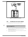
Installing the AC Power Adapter
Use the following procedures to connect the AC Adapter to the system:
c
Caution: Use only the AC Adapter supplied with the computer; other
adapters can damage the unit.
1.
Remove the AC adapter from the packaging. Connect the round coaxial connector
supplied with the notebook to the power receptacle on the rear of the
notebook as shown in Figure 2-10.
2.
Connect the female side of the AC Power cord to the AC Adapter and connect the
male end to a grounded AC outlet.
Installation 2-11
Figure 2-10
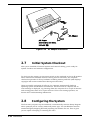
2.7
AC Adapter Installation
Initial System Checkout
After you’ve installed all internal options and external cabling, you’re ready for
system checkout and software configuration.
To check out the system, set the power switch on the notebook to the On (I) position
which initiates the notebook self test. During self test execution, the computer
checks the operation of all key hardware including memory and CPU (and displays
copyright and version number data during test execution).
Upon successful conclusion of self test, the computer automatically loads its
operating system and Windows environment. If self test fails to complete and an
error message is displayed, try powering down the computer for a couple of minutes
and turning power back on to repeat self test. If the error message persists, see
Section 6 for troubleshooting information.
2.8
Configuring the System
The first time you power up the notebook, it automatically runs the Setup Program
which prompts you for country name and printer type. You exit Windows and the
notebook begins unzipping files and preparing the software for use. Then it gives
you the option of keeping or removing the video.
2-12 Installation
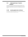
2.9
Making Backups of System
Software
The Notebook is preloaded with Windows 95 operating system software. Prior to
extended use of the notebook, create a backup set of system software using the
Backup Utility under Windows 95. In the event of a disk problem, you can restore
your system using the Restore Utility and the set of backup diskettes you’ve just
created.
2.10
Loading Application Software
For assistance in loading Application Software, refer to Chapter 5 in the Extensa
Series Notebook Computer User’s Reference Manual.
Installation 2-13
3
Operating Instructions
3.1
Introduction
The first two subsections describe the Extensa 450 Series Notebook operating
controls and indicators. The remainder of this section contains a summary of
computer operations related to notebook maintenance including how to restore
system software.
n
Note: For additional operating instructions, see Extensa 450 Series Notebook Computer Users Guide, TI Part No.9803942-0001.
3.2
Notebook Controls and Indicators
The Extensa Series Notebooks are equipped with the following controls and
indicators:
•
Group of five LEDs just above the keyboard (Sleep Mode, Hard Drive Activity,
Num Lock, Caps Lock and Scroll Lock)
•
Power, Setup, and Standby/Suspend buttons adjacent to the status LEDs
•
Single Power LED on the leftrear corner of the notebook
•
Touch Pad and two select buttons at base of keyboard
•
Contrast Switch on Display Assembly (Dual Scan models only)
These controls and indicators are shown in Figure 3-1 and described in greater
detail in the following paragraphs.
Operating Instructions 3-1
Figure 3-1 Extensa Series Controls and Indicators
3.2.1
LCD Contrast Control
The TFT version of the notebook contains no operating controls or indicators. The
Dual Scan version of the display contains a contrast switch on the lower right side
as shown in Figure 3-1.
3.2.2
Button Switches
The notebook contains two button switches above the keyboard including:
•
•
Power On/Off Switch- Alternate action, button type switch that controls power
to the unit.Pressing the Power button causes power to be applied to the
notebook and power up self test to be run. The PWR LED (left rear corner of
notebook) glows green and the computer then loads Windows 95. When the
Power button is pressed again, the Notebook powers down and all data in RAM
memory is lost.
Standby/Suspend Button Switch- an alternate action touch switch that
invokes the save to disk feature and places the unit in Standby Mode (if
previously On) or On if previously in Standby Mode.
3-2 Operating Instructions
3.2.3
Cover Release Latch
The Notebook contains one Cover Release latch . To open the notebook, slide the
Release Mechanism to the right and lift up on the front edge of the notebook cover.
3.2.4
Touch Pad Controls
The Extensa 450 Series Notebook Computers are equipped with a built-in mouse
device called “the Touchpad” physically located at the bottom of the keyboard (see
Figure 3-1).
The cursor is positioned by touching and draging your finger in the direction you
want the cursor to go. The select functions are performed either by tapping the
touch pad or by pressing the two buttons (switches) at the bottom of the keyboard.
You can change the operation of the pad by changing values in the mouse section of
the Windows 95 Control Panel. Once your cursor is in the proper place and you
want to select, use the left button to click or double click just as you would a mouse.
3.2.5
Keyboard Mode LEDs
The Notebook contains three “keyboard mode” indicators just above the keyboard
on the left side (notebook cover open). These LEDs include:
•
•
CAP (Caps Lock) Indicator- this LED indicates that the keyboard is locked in
the Uppercase mode. To switch to the Lowercase mode, press the Caps Lock
key on the keyboard.
NUM (Num Lock) Indicator- This LED lights when you press the Fn-F7
(NumLk) keys to toggle on the numeric keypad lock function. When the LED is
On, the embedded numeric keyboard keys generate AT-keypad characters and
functions when pressed in conjunction with the Fn key.
When the NUM indicator is Off, pressing the Fn key with the appropriate keys
provides cursor movement, paging and other functions in the normal mode.
When the NUM indicator is On, the embedded numeric keypad becomes a
temporary numeric keypad that does not require you to press any other key.
•
SCRL (Scroll Lock) Indicator- This LED lights to indicate that the keyboard is
locked in the scroll mode.
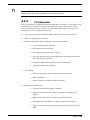
3.3
Operating Procedures
Some of the operating features useful for notebook maintenance are provided in the
following paragraphs. For additional operating instructions, refer to the Extensa
450 Series Notebook Computer User’s Manual, Texas Instruments Part No.
9803942-0001.
3.3.1
Floppy Drive Operating Procedures
To avoid damaging the floppy drive drive, and to protect data, take the following
precautions:
Operating Instructions 3-3
•
Never turn off or reset the notebook while the floppy activity indicator is lit.
•
Keep the AC adapter at least 6 inches away from your drive.
•
Insert the floppy into the floppy drive slot with the label side up and the
metal-shutter end first. Gently push the floppy into the floppy drive slot until
the floppy clicks into place.
•
To remove a floppy, press the eject button until the floppy pops out.
•
Never force open the access shutter on a floppy.
•
Always remove a floppy from the floppy drive before turning off the computer.
•
•
•
Never transport the commuter with a floppy in the floppy drive. Doing so can
damage the drive head.
If a floppy appears to be damaged, try to make a copy of it, and immediately
discard it.
Keep all floppies when not in use in a disk storage box to protect them from
damage or loss.
3.3.2
Installing/Removing PCMCIA Options
PCMCIA cards are inserted and ejected in much the same way as diskettes:
•
•
•
Type I or Type II PCMCIA options may be installed in the compartment on the
left side of the notebook. Type III Options may be installed on the right side of
the notebook with the Floppy Drive removed and the PCMCIA Option installed.
To insert a PCMCIA card, align the card with the socket and slide the card into
the socket until it locks into place. To install a Type III option, you must
remove the Floppy Drive.
To eject a PCMCIA card, go to the Windows 95 Control Panel, select PC Card
and select the card to stop; then press the release button and remove the
PCMCIA option.
3.3.3
Computer Hot Keys
The Extensa Series recognizes the following hot key sequences:
•
•
CTRL-ALT-DEL (warm boot)
CTRL-ALT-ESC (Enter setup screen); to use, power up notebook and press F8
at "Starting Windows 95" message. Select Command Prompt Only; then press
CTRL-ALT-ESC.
3-4 Operating Instructions
3.3.4
Responding to Low Battery Conditions
The computer generally will notify you when you are reaching a low battery
condition by the following:
•
Four short beeps per minute (unless battery warning is disabled)
The battery low warning is automatically disabled when the AC Adapter is installed
on the notebook regardless of the charge condition of the battery pack.
If the AC adapter is not plugged in within threeminutes of a detected battery low
condition, the notebook enters Suspend mode. When the notebook enters Suspend
Mode, it issues one beep,saves contents of RAM to disk and powers down the unit.
The Notebook returns to the normal operating mode when the power switch is
activated. Unit then recovers RAM information from the hard drive and restores
unit to previous "On" condition.
3.3.5
Minimizing Power Usage
The following actions can minimize power usage and protect your work during the
critical minutes before you shut the system down or replace on the battery packs
with a fully charged pack:
•
Press CTRL-STANDBY to shut off the alarm (if its enabled)
•
Save RAM Disk (if using RAM Disk feature)
•
•
Press Standby/ Suspend button to put the computer in Standby/suspend
mode whenever you are not actively using the computer. This will save all your
work and remember the application and file you were previously using when
you return to the On condition.
Power down the system if you do not need the computer
3.3.6
Recharging the Battery Packs
A standalone battery charger option is available to charge notebook battery packs.
The battery packs may also be charged in the notebook as follows:
1.
Install the battery pack in your computer (if not already installed).
2.
Connect the AC Adapter as described in Section 2.
3.
To fully charge the battery pack, leave it charging in the Notebook for at least
another 90 minutes.
3.3.7
Restoring Missing System Files
When you power up the Notebook, it automatically checks for certain key files that
must be present for normal system operation. If any of these files are accidently
erased as indicated by error message, insert the Windows 95 Startup Diskette and
reboot the system. This will allow you to boot up and troubleshoot your system.
Operating Instructions 3-5
3.3.8
Rebuilding the System Software
In the event of a hard drive replacement or system board replacement which
resulted in loss of system software, you may need to rebuilt the entire system
software structure.
The following items are required to rebuild the system software:
•
Set of backup diskettes of the system software
•
Operational Notebook
Insert the Windows 95 Startup Diskette in the Notebook’s floppy drive and power up
the system.
n
Note:For additional operating procedures, refer to to the Extensa 450 Series Notebook Computer User’s Manual, Texas Instruments Part No. 9803942-0001..
3-6 Operating Instructions
4
Theory of Operation
4.1
Introduction
This section describes the notebook theory of operation.
4.2
Notebook Functional Description
Functionally, the notebook computer consists of the following major subsystems:
•
Processor and Memory Subsystem
•
I/O Subsystem
•
Video Subsystem
•
Hard Disk Subsystem
•
Floppy Disk Subsystem
•
PCMCIA Subsystem
•
Serial Infrared Subsystem
•
Power Subsystem
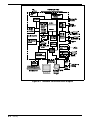
A functional block diagram of the Extensa Notebook is shown in Figure 4-1.
4.2.1
Processor/Memory Subsystems
The Processor function, housed on the Main Board, is implemented with a 75mhz
IntelDX4 Processor. The processor operates in conjunction with RAM and ROM
Memory on the Memory Board and other control logic on the Main Board to process
software instructions (BIOS, Windows 95, and Applications).
Primary control for the Processor/Memory subsystem is implemented with the
M1429L PC/AT Chipset. Address buffering and real time clock function is
implemented with an M1441L.
The memory subsystem, implemented on the Memory Board and optional Dual
Inline Memory Modules, provides 4MB (expandable to 32 MB) of fast DRAM
memory, 128 bytes of CMOS RAM (battery backed up) and 256 KB of Flash ROM for
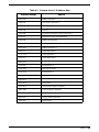
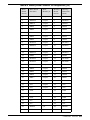
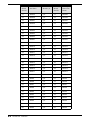
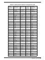
system and video BIOS storage. Tables 4-1 through 4-3 contain the Notebook I/O
address map, DMA channel assignments and IRQ interrupt level assignments
respectively.
Theory 4-1
Figure 4-1
4-2
Theory
Notebook Functional Block Diagram
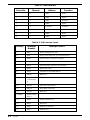
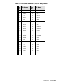
Table 4-1
Extensa Series I/O Address Map
Address Range
Device
000-00F
DMA Controller 1
020-021
Interrupt Controller-1
022-023
M1429 Registers
040-043
Timer 1
060-06E
Keyboard Controller 8742 Chip Select
070-071
Real Time Clock and NMI Mask
080-08F
DMA Page Register
0A0-0A1
Interrupt Controller 2
0C0-0DF
DMA Controller-2
1F0-1F7
Hard Disk Select
178,,17A
6377 Registers
1F0-1F7
Hard Disk Select
3F6,,3F7,
278-27F
Parallel Port 3
35F, 36F
Special I/O Ports
378,,37A
Parallel Port 2
3BC-3BE
Parallel Port 1
3C0-3C5
3C6-3C9
Video DAC
3C0-3CF
Enhanced Graphics Display
3D0-3DF
Color Graphics Adapter
3E0-3E1
PCMCIA Controller
3F0-3F7
Floppy Disk Controller
3F8-3FF
Serial Port 1
Theory 4-3
Table 4-2 DMA Channels
Controller
Channel
Address
Function
1
0
0087
Spare
1
1
0083
Spare
1
2
0081
Diskette
1
3
0082
Spare
2
4
Cascade
Cascade
2
5
008B
Spare
2
6
0089
Spare
2
7
008A
Spare
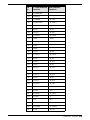
Table 4-3 IRQ Interrupt Levels
4-4
Priority
Interrupt
Number
1
SMI
Power management unit
2
NMI
Parity Error Detected,,I/O Channel Error
3
IRQ0
Interval Timer,,Counter 0 Output
4
IRQ1
Keyboard
IRQ 2
Interrupt from controller 2 (cascade)
5
IRQ8
Real Time Clock
6
IRQ 9
Cascaded to INT 0AH (IRQ 2)
7
IRQ10
Reserved
8
IRQ
11,Reserved
9
IRQ 12,PS/2 Mouse
10
IRQ13
INT from Coprocessor
11
IRQ14
Hard Disk Controller
12
IRQ15
Reserved
13 IRQ3
Serial Comm
Port 2
14
IRQ4
Serial Comm Port 1
15
IRQ5
Reserved
16
IRQ6
Diskette Controller
17
IRQ7
Parallel Port
Theory
Interrupt Source
n
Note: A PCMCIA card can use IRQ 3, 4, 5, 7, 9 and 11 as long as it does not
conflict with the interrupt address of any other device.
4.2.2
I/O Subsystem
The I/O subsystem, implemented with an NS87334 VJG Super I/O Controller Chip,
provides for such functions as internal Hard Drive control, floppy drive control,
serial and parallel ports and support for the Serial Infrared port. The Super I/O
Controller includes the following features: .
•
•
•
•
•
100 percent compatible with ISA, EISA, and Micro-channel architectures
Built-in Floppy Disk Controller
Software compatible with the DP8473, the 765A and N82077
•
16-byte FIFO (default disabled)
•
Burst and Non-burst modes
•
Perpendicular Recording drive support
•
New high-performance internal digital data separator (no external
filter components required)
•
Low-power CMOS with enhanced power-down mode
•
Automatic media-sense support
Two UARTS
•
Software compatible with the PC16550A and PC16450
•
MIDI compatible
•
Infrared support on UART2 (IrDA-compliant)
Bidirectional Parallel Port
•
Enhanced Paralle Port (EPP) compatible
•
Extended Capabilities Port (ECP) compatible, including level 2
support
•
Bidirectional under either software or hardware control
•
Compatbile with ISA, EISA, and Micro Channel architectures
•
Ability to multiplex FDC signals on parallel port pins for external
FDD
Theory 4-5
•
•
Integral IDE controller
•
•
•
Includes protection circuit against damage caused when printer is
powered up, or operated at higher voltages
Provides a complete IDE interface with DMA control (except for
optional buffers)
Integral address decoder- provides selection of all primary and secondary ISA
addresses including COM1-4 and LPT1-3.
Enhanced Power Management Function
•
Special configuration registers for power down
•
Enhanced programmable power-down and wake-up modes
•
Auto power-down and wake-up modes
•
3 special pins for power management
•
Typical current consumption during power-down is less than 10A
4.2.3
Video Subsystem
The video subsystem, implemented on the Main Board and on the LCD Display
Unit, displays text, graphics and drives an external VGA port. The video subsystem
is implemented with a Cirrus Logic 6245 high performance flat panel/RT VGA
controller and supporting logic and video RAM (512KB).
The major features of the VGA controller include:
•
•
•
•
•
•
4-6
Theory
Highly integrated design (flat panel / CRT VGA controller, RAMDAC, clock
synthesizer)
Multiple Bus Architecture Integrated Interface
•
Local Bus (32-bit CPU Direct and VL)
•
EISA/ISA (PC/AT) 16-bit Bus
Advanced frame buffer architecture uses available display memory, maximizing
integration and minimizing chip count
Integrated programmable linear address feature accelerates GUI performance
High performance resulting from zero wait state writes (write buffer) and
minimum wait state reads (internal asynchronous FIFO design)
Supports panel resolutions up to 1280 x 1024 resolution including 800x600
and 1024x768
•
SMARTMAP intelligent color to gray scale conversion enhances text legibility
•
Text enhancement feature improves white text contrast on flat panel displays
•
Fully Compatible with IBM VGA
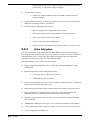
4.2.3.1
External VGA Drive Capability
On the Extensa 450, the external VGA port is provided by the port adaptor fixture
in the form of a 15-pin, female, D-type connector which can be used to drive an
external CRT (standard VGA modes with resolutions of 800 X 600 X 256, or 640 X
480 X 256 ).
4.2.4
Hard Disk Subsystem
The Hard Disk Subsystem, controlled by the IDE interface compatible NS87334
VJG Super I/O Controller on the Main Board, provides disk storage for all system
software and user files. Initially, the 450 Series Notebooks are equipped with a 340
Million Byte hard drive. However, the onboard controller can support high capacity
drives.
During the manufacturing process, Texas Instruments formats the hard disk and
then loads all supplied software including Windows 95.
c
Caution: Formatting the disk drive erases any data that may be stored
on the disk. Therefore do not attempt a format of the hard disk unless
the computer self-test and diagnostics confirm that the disk has not
been formatted.
A Hard Drive activity LED is located along the front edge of the notebook. This LED
lights during hard driver read/write accesses.
c
Caution: The notebook should not be moved when the HDD LED is lit to
prevent accidental damage to the hard drive.
4.2.5
Floppy Diskette Drive Subsystem
The Floppy Diskette Drive Subsystem consists of a Floppy Controller and the Floppy
Diskette Drive. The Floppy Diskette Drive can read/write standard 3.5-inch
minidiskettes.
4.2.6
PCMCIA Subsystem
The notebook is equipped with an on-board PCMCIA host adapter (CL-PD6722
PCMCIA Controller) and sockets to support one Type I or Type II option or a Type III
option if the Floppy Drive is removed from the unit. The PCMCIA Controller has the
following features:
•
Single-chip PCMCIA host adapters
Theory 4-7
•
Direct connection to ISA (PC AT) Bus
•
Direct connection to PCMCIA 2.0 Bus
•
PCMCIA 2.0- and JEIDA 4.1-compliant
•
82365SL-compatible register set, ExCA-compatible
•
Automatic Low-power Dynamic Mode for lowest power consumption
•
Programmable Suspend Mode
•
Five programmable memory windows per socket
•
Two I/O windows per socket
•
Programmable card access cycle timing
•
8- or 16-bit CPU interface
•
8- or 16-bit PCMCIA interface support
•
ATA disk interface support
•
Automatic flash memory timing support
•
Easy host interface using ISA I/O addresses 03E0h, 03E1h
•
Mixed-voltage (3.3V or 5V) operation
•
Dual-socket-interface, 208-pin QFP
4.2.7
Power Subsystem
The Power Subsystem consists of the following major parts:
•
•
•
Power Management (hardware and software components)
AC Adapter
Primary Battery Board
•
Primary Battery Pack
•
Secondary Battery Board
•
Secondary Battery Pack
4.2.7.1
Power Management
The notebook is equipped with a power management function that minimizes
battery usage for prolonged battery operation and automatically recharges the
batteries when the notebook is used with an AC adapter.
The power management modes and warnings include the following:
4-8
Theory
•
LCD standby mode
•
Hard disk standby mode
•
System standby/suspend mode
•
Battery-low warning
•
Standby/suspend upon battery low
4.2.7.2
AC Adapter
The notebook uses an AC adapter with built in over voltage and short circuit
protection.
The adapter can with stand a continuous short-circuit to DC output without
damage to the notebook logic components. The adapter operates in shut down mode
shorting Vo trail and resets to the normal power mode after the fault condition is
removed.
4.2.7.3
Primary Battery Pack
The Extensa Series Notebooks use the Duracell DR35 as the primary battery pack.
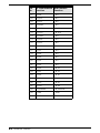
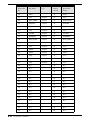
Specifications for the Primary Battery Pack are provided in Table 4-4.
Table 4-4 Primary Battery Pack Specifications
Function
Specifications
Battery type
NiMH (Nickel Metal-Hydride)
Cell structure
9 cells per pack (in series)
Nominal voltage
10.8 V
Cell energy capacity,
Typical,
Minimum
2400 mAH
2500 mAH,
2330 mAH,
Nominal rated capacity
27 Watt-hours
Operating Temperature_,
Discharge,
Charge
-20 to 50°C (at 95%RH),
0 to 45°C (at 95%RH),
Charge and discharge
cycles
500 (minimum),
Weight
470 grams
Battery discharge time
3 hours (with APM)
Battery charge time
Theory 4-9
4.2.7.4
Secondary Battery Pack
As an optional feature, the Floppy Drive can be removed from the notebook and a
Li-Ion (Lithium Ion) secondary battery pack can be installed in the same cavity to
provide additional battery operating time.
4-10
Theory
5
Troubleshooting Procedures
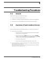
5.1
General
This section provides the following information:
•
Overview of the fault isolation process
•
Guidelines for isolating computer malfunctions to replaceable subassemblies
•
Instructions for executing diagnostics and interpreting error messages.
5.2
Overview of Fault Isolation Process
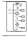
The fault isolation process (summarized in Figure 5-1) consists of the following:
•
•
Quick Check of the following:
•
Notebook power system (including battery packs and AC Adapter
connections)- See Paragraph 5.4.
•
Switch settings (ensure Power switch is On, and press Standby
switch to ensure that Notebook is not in Standby mode; press Shift
to ensure the notebook is not in Auto-Suspend mode.
•
All external cabling (if any)
•
Check LCD Contrast adjustment (Dual Scan version only)
Record and attempt to resolve any displayed error messages/LED indications
(See Paragraph 5.3 and Table 5-1)
Record and attempt to resolve any series of beeps emitted from the notebook
indicating test failure (See Table 5-2)
Troubleshooting 5-1
START
COMPUTER
TROUBLE
INDICATION
?
WHEN POWER SWITCH
SET TO ON,, NO
INDICATION OF POWER;
SCREEN DARK, STATUS
LED's EXTINGUISHED
DEAD
COMPUTER
SYMTOMS
?
NO
YES
SEE
PARAGRAPHS
5.3.1 & 5.3.2
NO
SET POWER SWITCH
TO ON. SELFTEST
AUTOMATICALLY RUNS
RUN
SELF TEST
ERROR
MESSAGE
?
YES
SEE PARAGRAPH
5.3.4
NO
MODEM
PROBLEM
?
YES
SEE PARAGRAPH
5.3.5
NO
RUN
DIAGNOSTICS
DIAGNOSTICS
ERROR MSG
?
YES
See Appendix D
(PC Doctor)
NO
Figure 5-1 Troubleshooting Flowchart
5-2 Troubleshooting
•
•
•
•
•
Try rebooting the system (CTRL-ALT-DEL); restore system from diskettes, if
necessary.
If the computer is capable of running the Setup program; check the serial and
parallel port configurations, and other features that may affect system
operation.
Run Diagnostics to further isolate problem area (See Paragraph 5.3.5).
For indicated hardware failures, cycle power and repeat self test to verify that a
hard failure has occurred.
Remove and replace suspect hardware (as described in Section 6 of this
manual) and retest the system using the diagnostic tests as described in
paragraph 5.3.5.
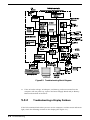
The detailed block diagram, shown in Figure 5-2, is useful in performing fault
analysis of various internal subsystems. For example, an LCD hardware problem
can be traced to either the LCD, Inverter Board, VR Board, or Battery Board. Other
subsystem problems can be isolated in a similar fashion using the detailed block
diagram as a troubleshooting tool.
5.3
Troubleshooting Procedures
The built-in self test program and the disk resident diagnostics program (PC-Doctor)
are useful tools in computer troubleshooting. However, if the computer has a power,
keyboard or display problem, you first solve this problem before running
diagnostics. If the computer powers up and displays messages on the LCD or emits
a series of beeps, skip to Paragraph 5.4.3 for further instructions.
5.3.1
Troubleshooting a Power Supply Problem
If the computer does not power up when the Power Switch is set to the ON position,
you most likely have a malfunction in the power subsystem (loss of power at the AC
Outlet, faulty AC Adapter, discharged Battery Packs, or faulty Power Supply Board).
With a power problem, all LEDs are extinguished, the LCD screen is blank, the
system does not respond when the standby switch several times consecutively and
no drive activity can be heard. The computer is unable to load software and
displays no visible signs of activity.
To fault isolate a power problem, check the following:
•
•
•
AC Adapter and Battery- Plug in the AC adapter and double check all
connections on the Adapter and computer. Ensure that the Notebook Power
switch is set to the On position and that the system is not in Standby or sleep
mode.
Measure the voltage at the AC Outlet or plug in a known good appliance (EG. a
lamp) to verify that voltage is present. If the voltage is O.K., try replacing the
AC Adapter
Check to see that the battery pack is installed correctly (try using a recharged
battery pack if batteryis discharged).
Troubleshooting 5-3
Figure5-2 Troubleshooting Block Diagram
•
If the AC outlet voltage, AC Adapter, and battery packs test normal but the
computer will not power up, replace the Power Supply Board and/or Battery
Board as described in Section 6.
5.3.2
Troubleshooting a Display Problem
If the LCD remains blank when you turn on the computer, and the status indicators
light, check the following controls on the display (See Figure 3-1):
5-4 Troubleshooting
•
•
•
•
LCD standby mode - If the LCD backlight remains off, even with the Contrast
Control set to its highest position, the LCD may be in Standby Mode. Press the
Standby or Power button to power up the system.
Notebook Set for External Monitor- use CMOS Setup to reset notebook.
LCD - Replace the cover-display assembly as described in Section 6 of this
manual.
Low battery - Use a fully charged battery.
5.3.3
Fault Isolation Using Selftest
When the computer is first powered up, it automatically performs a self-test of its
central hardware and memory functions. During self-test (which lasts for a few
seconds), the display shows copyright and version number information.
n
Note: Some procedures in this paragraph require you to use keystroke sequences, such as Ctrl-Alt-Del. To execute a keystroke sequence such as
this, you must press all three keys simultaneously.
5.3.3.1
Self Test Error Messages
Upon successful completion of the self-test, the computer automatically loads its
operating system and other built-in utilities. If the self-test fails to complete
successfully, the display shows one of the error messages described in Appendix A.
5.3.4
PCMCIA Modem Problems
If an optional PCMCIA modem does not work properly, check the following items:
•
•
•
•
Proper installation of any PCMCIA options (check Modem settings under
Control Panel).
Dialing problem or wrong number - Try dialing a number that you have
previously dialed successfully.
Faulty phone line - Connect a telephone to the line and listen for a dial tone.
Software program - Check to ensure that you have installed the software
correctly.
Troubleshooting 5-5
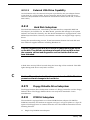
5.3.5
Fault Isolation Using Diagnostics
PC-Doctor supplied with the Extensa 450 Series Notebooks is a powerful
diagnostics tool that can help you scan an internal RAM system for viruses,
determine the hardware configuration of a local or remote system, benchmark its
performance, analyze the performance of all subsystems, and perform a suite of
interactive and non-interactive tests on attached devices. The test results are stored
in a log which can be printed out (by pressing F2) or saved in a disk file (by pressing
F3).
Features of the diagnostic program are accessed through a series of pull-down
menus and basic keyboard keys (cursor keys to move highlighted pointer, Enter key
to select a highlighted feature, ESC key to cancel a function and move back one
level.
PC-Doctor is typically user friendly but if you don’t understand a feature,
context-sensitive “help” information is available at any time by pressing the F1
function key; pressing the F1 function key twice accesses the online Technical
Reference Manual for PC-Doctor.
A powerful set of utilities within PC-Doctor (that can be run locally or remotely)
simplify the task of determining system configuration data, allocating and using
system memory, IRQ and DMA use, what device drivers are installed, what COM
and LPT ports are assigned and what ports are available, identifying partitioning
data for fixed disk drive(s), determining the VGA setup information, reading the
software interrupts/interrupt vectors, etc.
Functionally, PC-Doctor includes the following:
•
•
•
•
Group of nine non-Interactive diagnostic tests that perform a non-destructive
test of the major hardware functions in the notebook (Processor, Memory,
System board, video section, serial and parallel ports (when loopback adapters
are installed), hard disk and floppy disk.
Group of seven Interactive tests (require operator input) for testing the
keyboard, video sections, sound subsystem, mouse, joystick, diskette drive,
printer subsystem and SCSI/CD-ROM Drive subsystems.
Utility that provides detailed system information such as configuration data,
allocation and use of system memory, IRQ and DMA use, what device drivers
are installed, what COM and LPT ports are assigned and what ports are
available, partitioning data for fixed disk drive(s), VGA setup information,
software interrupts and interrupt vectors.
Group of special purpose utilities to run other tests from PC-Doctor, perform a
virus scan of the internal RAM system, edit configuration files, surface scan
hard drives, measure system performance, open a DOS prompt, provides
terminal access to devices connected to serial ports, supports memory debug
operations, enables remote operations, permits deep discharge of notebook
batteries and provides an extensive test reporting function.
The PC-Doctor diagnostic program contains a group of nine non-Interactive
diagnostics, available from the Diagnostics heading in the main menu, that
permits testing various hardware sections without operator input. You can select
one, several, or all tests from the Diagnostics menu. These tests are
non-destructive; the serial and parallel port tests require disconnecting external
5-6 Troubleshooting
devices from your notebook and installing loopback plugs. The Non-Interactive test
categories include:
•
CPU and Co-Processor Tests
•
Base RAM memory test
•
System Board test
•
Video Test
•
Com1 and LPT1 serial port tests
•
Parallel Port Test
•
Fixed Disk test
•
Diskette Drive tests
•
Other devices (Sound card, PCMCIA options, etc.)
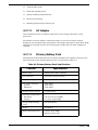
Interactive Tests
The PC-Doctor diagnostic test includes a suite of seven Interactive tests that require
operator input during the course of the test. The Interactive Tests category
includes:
•
Keyboard- tests the keyboard keys, LEDs and repeat function
•
Video-tests the LCD and external VGA character sets, and colors.
•
Speaker-tests the volume response at different frequencies.
•
Mouse-tests the mouse driver, buttons and functionality
•
Joystick- calibrates the external joystick connected to the system
and tests the joystick buttons
•
Diskette Drive- checks diskette drive functionality
•
Maximum System Load- thoroughly exercises system to the
maximum extent possible for performing system “burn-in and test
•
Printer Test- tests the operation of a connected printer
•
SCSI Test- sends test codes to attached SCSI devices (requires use
of a Docking System with SCSI)
•
CD-ROM Test- checks out any attached CD-ROM Drive (requires
attachment of a Docking System with CD-ROM capability)
Troubleshooting 5-7
Supporting Online documentation
The PC-Doctor Diagnostic contains the following online information sources:
•
•
Online Technical Manual- selected at any time by pressing F1 key twice or by
clicking on the Question Mark in the upper left hand corner of any PC-Doctor
Menu
On-line Help system that provides context sensitive information from every
PC-Doctor screen- accessed by pressing F1 key once (pressing F1 twice gets
you into the online manual)
5.3.5.1
User Interface to PC-Doctor
PC-Doctor is structured as a text-mode, windowed user interface with pull-down
menus. Program operation requires the use of the following keys:
•
Cursor Keys- move the highlighted pointer
•
ENTER Key- Selects the highlighted option
•
ESC Key- Cancels current function and goes back one step
•
F1 Key- Activates the context-sensitive help feature (pressing F1 twice in a row
calls up the online Technical Reference Manual for PC-Doctor)
Scrolling windows, which show the results of various operations, use the following
keys:
•
Page Up/Page Down- moves the screen one page at a time
•
F2- Prints the log to PRN
•
F3- saves the log to a file
You can also use the mouse or Point to interact with PC-Doctor. The leftmost Select
key is used to choose objects (menu entries and action codes typically enclosed in
brackets). The rightmost Select key is equivalent to the ESC key which takes you
back to your previous step.
5.3.5.2
Creating a Bootable Floppy Diskette
Prior to using PC-Doctor, create a bootable floppy diskette using the following
procedure:
1.
Power up the unit; when unit displays message, "Starting Windows 95", press
F8. Choose Command Prompt Only from menu.
2.
Using DOS, format a floppy diskette.
3.
From the A: prompt, copy the basic MS-DOS files to the diskette using the
following command:
Format A: /F:1440 /S
5-8 Troubleshooting
Where the value 1440 is the capacity of the diskette (1.44 MB in this example).
4.
Get into the PC-Doctor directory ( type CD C:\PCDR and press Enter)
5.
Copy the PC-Doctor files to the bootable diskette using the following
command:
XCOPY C:. A:.
After completion of this procedure, you should have a bootable diskette containing
PC-Doctor.
5.3.5.3
Running PC-Doctor
PC-Doctor is a DOS-resident program that can be run from either hard disk or from
the bootable diskette you previously created.
n
1.
From the C:\ prompt change directory (type CD C:\PCDR) and press Enter
2.
The Diagnostics Program loads into system memory, and the LCD displays the
diagnostics Header.
Note: There are a number of command-line switches that can be entered
when starting up PC-Doctor to enable automatic virus scanning, enable
loopback testing of serial/parallel ports, work from the remote menu if performing remote operations, etc. To get a listing of the available commandline switches, startup PC-Doctor with the following command:
PCDR /? and press Enter.
n
Note: If PC-Doctor detects a virus, it will stop with an error message. You
must then use one of the standard virus detection and removal programs to
remove the virus.
5.3.5.4
Quitting PC-Doctor
To exit PC-Doctor, Select the Quit pull down menu and then select the Quit to DOS
option.
n
Note: For additional information, press F1 twice to access the online Reference manual for PC-Doctor.
Troubleshooting 5-9
6
Field Service
6.1
Introduction
This section contains preventive and corrective maintenance procedures for the
Extensa 450 Series Notebook Computers. The first part of the section describes the
computer cleaning procedures and preferred handling procedures for sensitive
components (e.g. disk drives, batteries).
The second part of the section identifies all field replaceable parts; the remainder of
the section contains removal and replacement procedures for the field replaceable
parts.
6.2
Preventive Maintenance
Preventive maintenance is limited to cleaning the plastic case, the keyboard, and
the display screen.
6.2.1
Cleaning the Computer
When it is necessary to clean the plastic case and keyboard, use a soft, lint-free
cloth, slightly dampened with a mild detergent solution or use the contents of any
commercially available computer cleaning kit.
c
c
Caution: Never use alcohol, petroleum-based solvents, or harsh detergents to clean your computer. Also never spray any liquids directly on
the computer case, keyboard, or screen. If the liquid-crystal display
(LCD) screen has become smeared or dusty, clean the screen by first applying a mild glass cleaner to a soft, clean, lint-free cloth, and gently
wipe the glass. Never apply liquids directly on the screen surface.
Caution : Do not use paper towels to clean the display screen. Paper can
scratch the display screen matte.
Field Service
6-1
6.2.2
Protecting the Disk Drives
To protect the disk drives and data, back up the system disk periodically on floppy
diskettes. Periodically use a head-cleaning diskette in the floppy diskette drive to
prolong the life of the drive and to help maintain data integrity.
6.2.3
Handling the Computer Battery Pack
The battery pack furnished with the computer requires reasonable care and
handling to ensure efficient operation and maximum life. Periodically inspect the
battery terminals and the batteries for evidence of corrosion and oxide build-up;
clean if necessary.
To ensure that the battery pack endures a normal life cycle, always observe the
following precautions when handling the battery pack:
•
•
Do not drop the battery pack or subject it to excessive shock and vibration.
Do not expose the battery pack to direct sunlight, moisture, or chemical
compounds.
•
Do not disassemble the battery pack.
•
Do not use the battery pack to power other devices.
•
Do not short the battery leads or connect the battery with reversed polarity.
•
•
Never attempt to charge the battery pack in any way other than as described in
this manual.
Always charge the battery pack as soon as possible after a low battery
indication.
6.2.4
Restoring System Software
The hard drive on the notebook computer is factory loaded with Windows 95 and
ready for operation. Supplied with the Windows 95 system is a facility for creating
backup diskettes of the system software. In the event of a disk crash or other
problem, you can use the Windows 95 Startup diskette to boot the unit and
perform troubleshooting.
6.3
Required Tools and Equipment
All notebook computer corrective maintenance procedures can be performed using
the following tools: Tweezers
6-2
•
Small flat-blade screwdriver
•
Small Phillips screwdriver
•
Hexagonal Screwdriver
•
Plastic Stick
Field Service
c
Caution: All boards, options and peripherals contain components that
are sensitive to static electricity. When handling any of these items, protect against static electricity by using wrist or ankle grounding straps
and grounded working mats. When moving or storing items, use the antistatic bags supplied with the items.
6.4
Notebook Field-Replaceable Parts
and Assemblies
All members of the Extensa 450 Series Notebook Computers contain two major
assemblies including the Cover Display Assembly (upper half of notebook computer)
and the System Base Assembly (lower half of the notebook). Each of these two
assemblies contain FRUs as described in the following subparagraphs.
6.4.1
Cover-Display Assembly
As shown in Figure 6-1, the Cover-Display Assembly contains the LCD screen,
Power Inverter Board, and Converter Board.,The DSSTN models also include a Slide
Pot Board (not used with the TFT models).
The Field Replaceable Units (FRUs) within the Cover Display Assembly are provided
in Table 6-1.
n
Note: FRU level part numbers are not available at time of publication of this manual. For required part numbers, reference the Field Service Bulletins (FSBs) for the
Extensa 450 Series or contact Texas Instruments by dialing 1-800-TI TEXAS.
Bezel (Removed
for Clarity)
Power Inverter
Board
LCD Cover
Slide Pot/Converter
Board
Figure 6-1
Cover Display Assembly FRUs
Field Service
6-3
Table 6-1 Cover Display Assembly, Field Replaceable Units (FRUs)
FRU Description
Reference FRU Description
Paragraph
No.
Reference
Paragraph
No.
Inverter Board, DSSTN
10.4"
6.5.9
LCD Cover, DSSTN
10.4", 450
6.5.9
Inverter Board, TFT 9.4"
6.5.9
LCD Cover, TFT 9.4",
450T
6.5.9
Display Assembly, 10.4"
DSSTN 450
6.5.8
Bezel, DSSTN 10.4",
450
6.5.9
Display Assembly, 9.4"
TFT 450T
6.5.8
Bezel, DSSTN 10.4",
455
6.5.9
Slide Pot Board, DSSTN
10.4"
6.5.9
Bezel, TFT 9.4", 450T
6.5.9
Converter Board, TFT
9.4"
6.5.9
Bezel, TFT 9.4", 455T
6.5.9
6.4.2
System Base Assembly
As shown in Figure 6-2, the System Base Assembly houses a variety of
field-replaceable subassemblies and components. The FRUs and paragraph
references for removal/replacement procedures are listed in Table 6-2. Table 6-3
contains a listing of Customer (non-technical user) replaceable units (CRUs) and
associated TI Part Numbers.
n
Note: FRU level part numbers are not available at time of publication of this manual. For required part numbers, reference the Field Service Bulletins (FSBs) for the
Extensa 450 Series or contact Texas Instruments by dialing 1-800-TI TEXAS.
Figure 6-2 Base Assembly FRUs
6-4
Field Service
Table 6-2 Base Assembly, Field Replaceable Units (FRUs)
FRU Description
Reference
Paragraph
No.
FRU Description
Reference
Paragraph
No
Main Board Assembly
6.5.16
Touch Pad Assembly
6.5.11
Memory Board Assembly
6.5.15
Heat Sink Assembly
6.5.6
Serial IR Board Assembly
6.5.12
HDD Cable
6.5.4
Primary Battery Board
Assembly
6.5.13
FDD Cable
6.5.4
Secondary Battery
Board Assembly
6.5.17
HDD Cover Assembly
6.5.4
Power Supply Board
Assembly
6.5.14
HDD Holder Assembly
6.5.4
Floppy Drive Assembly
6.5.3
Lower Case Assembly
Ref
Hard Disk Drive, 340
Million Byte, 12.5mm
6.5.4
Upper Case Assembly
6.5.10
Keyboard Assembly
6.5.5
Table 6-3 Notebook CRUs (Customer Replaceable Units)
CRU Description
TI Part No.
Reference
Paragraph
No.
Internal Battery Pack, Ni-MH
9803928-0001
6.5.1
Battery Pack, Li-ION (Option)
9803929-0001
6.5.3
4MB RAM Module
9803932-0001
6.5.7
8MB RAM Module
9803950-0001
6.5.7
16B RAM Module
9803933-0001
6.5.7
External Battery Charger
9803934-0001
Ref.
Port Expander (TravelBud)
9803935-0001
Sec. 2
Full Function Port Replicator
9803936-0001
Ref.
PCMCIA Option
9803930-0001
Sec. 2
Field Service
6-5
6.5
Notebook Subassembly Removal
and Replacement Procedures
The following paragraphs contain field service-level removal/replacement
procedures for the Notebook.
c
Caution: Prior to removing any of the internal FRUs in the notebook, remove the AC Adapter, battery, floppy and hard drives and all external options installed on the notebook.
6.5.1
Removing/Replacing the Notebook Battery
Pack
The procedure for removing and replacing the battery pack(s) is as follows:
1.
Turn off the computer.
2.
Locate the battery door (right side of notebook near the front) (see Figure 6-3).
Press the battery door inwards and slide the door toward the front of the
notebook; remove the battery door.
3.
Grasp the ribbon loop on the battery and pull the battery out of the
compartment..
4.
When replacing the battery, insert the end opposite the ribbon loop with the
battery notches pointing upwards. Slide the battery into the compartment
and replace the battery door.
Figure 6-3 Removing Battery and Disk Drives
6-6
Field Service
6.5.2
Removing/Replacing PCMCIA Options
The procedure for removing and replacing the PCMCIA options is as follows:
1.
Turn off the computer.
2.
Remove the PCMCIA device(s).
3.
To replace the PCMCIA Device, open the cover door and insert the device.
Reinstall any external cabling required for the device.
6.5.3
Removing/Replacing the Floppy Drive
To remove and replace the Floppy Drive, perform the following procedure:
c
n
1.
Remove the battery as described in Paragraph 6.5.1 above.
2.
Turn the notebook over so that the bottom is facing up and the floppy drive is on
the right side. Lay the notebook on a padded, flat work surface.
3.
Locate the Floppy Release Button near the center of the notebook (Figure 6-3).
Caution: When removing the Floppy Drive Assembly, grasp it by its
sides; otherwise damage to the floppy drive can occur.
4.
Push the Floppy Release Button toward the front of the notebook and
simultaneously pull outwards on the floppy drive by placing your thumb
over the ribbed outer edge of the floppy drive assembly. When the floppy
drive is released, grasp the assembly by the two sides and remove the
assembly from the notebook.
5.
The Floppy Drive Assembly can be further disassembled by removing the
Phillips-head screws from the sides of the floppy drive assembly; lifting off
the cover and lifting out the floppy drive and cable connector (ZIF Connector
type). Unplug the cable at the ZIF Connector .
Note: When reassembling the floppy drive, it’s easier to install the shield on the
floppy drive before installing the drive into the plastic housing.
6.5.4
Removing/Replacing the Hard Drive
The procedure for removing and replacing the Hard Drive assembly is as follows:
1.
Power down the notebook, remove the battery packs, and disconnect the AC
Adapter, if installed.
2.
Disconnect any peripheral device interface cables from the external interface
connectors and remove any installed PCMCIA options.
Field Service
6-7
3.
Turn the computer over so that the Hard Drive panel is on your right side (See
Figure 6-3). Press down on the circular bump with your thumb to release the
hard drive cover; remove the cover and lay aside for later reinstallation.
4.
Using finger pressure, slide the metal cover downwards toward the edge of the
notebook; then lift upwards to remove the metal cover.
5.
Insert a small blade straight slot screwdriver into the recess in the plastics and
gently lift the frontmost edge of the drive out of the bay.
6.
Lay the hard drive on its back.Then using a small straight slot screw driver, gently
pry on each end of the connector on the Disk Drive and rock it back and
forth until the connector is removed from the drive assembly.
7.
Replacement is essentially the reverse of steps 1 through 6.
6.5.5
Removing/Replacing the Keyboard Assembly
The procedure for removing and replacing the keyboard assembly is as follows:
1.
Turn off the computer and disconnect the ac power adapter (if it is attached).
2.
The top edge of the keyboard is held in place by plastic tabs beneath the CTRL
and Right Arrow Keys. Pull the tabs toward the front of the notebook (tabs
snap into an 1/8 inch recess in the plastics).
3.
Using a small straight-blade screwdriver, lift the front edge of the keyboard
upwards.
4.
Lift the front edge of the keyboard slightly and gently pull the keyboard towards
the front of the notebook exposing two cables that connect the keyboard to
the main board.
5.
Release the two ZIF (zero insertion force ) connectors using a plastic stick or other
nonmetallic object and remove the cables from the main board connectors
6.
Remove the keyboard assembly from the notebook.
7.
When installing the replacement keyboard, essentially reverse the above
procedures.
6.5.6
Removing/Replacing the Heat Sink
To remove and replace the heat sink, perform the following procedure:
6-8
1.
Remove the keyboard assembly as described in paragraph 6.5.5.
2.
Remove the two Phillips-head screws that secure the heatsink to the main board
(note that one of the screws is located near the HDD connector).
3.
Lift upwards on the heatsink and remove it from the base.
4.
Replacement is the reverse of steps 1 through 3 above.
Field Service
6.5.7
Removing/Replacing Dual Inline Memory
Modules (DIMMS)
To remove and replace the expansion memory, use the following procedure:
1.
Loosen the keyboard assembly (but do not disconnect keyboard cables) as
described in steps 1 through 5 of Paragraph 6.5.5).
2.
Remove the Heatsink as described in Paragraph 6.5.6.
3.
Using the back edge of the keyboard as a hinge, lift the front edge of the keyboard
up and lay it against the LCD assembly.
4.
Push the two metal springs away from the board edge and remove the DIMMS
board.
5.
When installing a DIMMS board, insert the edge of the board into the rear of its
connector using a slight rocking motion at an angle to the surface of the
board.
6.
Once the DIMM is fully inserted in the connector, push downwards on both sides
of the board to snap it in place.
Figure 6-4 Removing/Replacing Expansion RAM
Field Service
6-9
6.5.8
Removing and Replacing the Cover-Display
Assembly
To remove the cover-display assembly, perform the following procedure:
1.
Remove the keyboard and heatsink as described in paragraphs 6.5.5 and 6.5.6
respectively.
2.
Remove the cable cover below the display by lifting upwards on the front edge of
the cover.
4.
Unplug the video cable that mates with the Main Board.
5.
With the main video cable out of the way, two smaller cables are visible. Unplug
the rightmost cable.
6.
Using a plastic stick, slide the right and left hinge covers away from the base
assembly.
7.
Lay the display completely back and remove the four screws that secure the
display hinges to the base case assembly.
8.
Ensure that the display cables are free from the top case assembly and remove
the display assembly.
9.
Reinstallation of the Display Assembly is the reverse of steps 1 through 8 above.
6.5.9
Removing and Replacing the Inverter Board
To remove and replace the Inverter Board assembly, perform the following
procedure:
c
6-10
Caution: If the notebook is powered up with the LCD bezel removed,
you can be exposed to high voltages which could result in shock and
equipment damage. Ensure that the batteries and AC adapter are removed from the notebook when working on the LCD/Display assembly.
1.
Use a narrow piece of plastic or pointed tweezers to apply light pressure to one
edge of the lower screw covers. The lower screw covers will bow outwards
and can be removed.
2.
Remove the rubber upper screw covers using a pair of tweezers.
3.
Remove the six screws that secure the bezel to the display assembly (a small
Phillips-head screwdriver is recommended for removing the two screws at the
top of the bezel).
4.
Pull on the inside edges of the bezel; remove bezel and lay aside for later
reinstallation.
5.
Peel back the EMI shield along the right side of the display to expose the Inverter
Board.
6.
Disconnect the connectors at the top and bottom of the Inverter Board.
7.
Use the small Phillips-head screwdriver to remove the two screws holding the
Inverter Board; remove the Inverter Board Assembly.
Field Service
8.
Reinstallation of the Inverter Board is the reverse of steps 1 through 7 above.
6.5.10
Opening/Replacing the Top Case Assembly
To remove/replace the Top Case Assembly, perform the following procedure:
1.
Remove the Keyboard Assembly and Heat Sink Assembly as described in
Paragraphs 5.5.5 and 5.5.6.
2.
Remove the four screws that secure the Top Case Assembly to the base. Note that
the screw at the rear of the opening is shorter than the remaining three
screws.
3.
Using a plastic stick, unlock the ZIF connector located near the glide pad and
remove the cable from the connector.
4.
Remove the cable cover below the display by lifting upwards on the front edge of
the cover.
5.
Turn the notebook over and remove the six Phillips-head screws from the bottom
of the notebook.
6.
Rotate the notebook so that the rear of the unit is facing you; remove the rear
door assembly by bowing it outwards.
7.
Several recesses are located just above the two rear connectors. Use a small
flat-blade screwdriver to disengage the snaps associated with the right and
left recesses.
8.
Lift and push the Display Assembly forward to disengage it from the Base
Assembly.
9.
Replacement of the Top Case Assembly is the reverse of steps 1 through 8 above.
6.5.11
Removing/Replacing the Touch Pad
Assembly
To remove and replace the Touch Pad Assembly, perform the following procedure:
1.
Remove the Top Case Assembly as described in the previous paragraph.
2.
Turn the Top Case Assembly over and remove the four screws that secure a metal
shield to the plastics.
3.
Lift the plastic frame that rests on top of the touch pad.
4.
Unplug the flex cable from the connector on the touch pad. Note that the board
connector is a LIF (Low insertion force) type; the cable is held in place by
friction.
5.
Slide the board assembly to the right and remove from the unit.
6.
Replacement of the Touch Pad Board Assembly is essentially the reverse of Steps
1 through 5 above.
Field Service
6-11
Figure 6-5 Touchpad Removal/Replacement
6-12
Field Service
6.5.12
Removing/Replacing the SIR Board
To remove and replace the SIR Board, perform the following procedure:
1.
Remove the Top Case Assembly as described in paragraph 6.5.10.
2.
Unplug the SIR Board cable connector from the Main Board (small leftmost cable
connector at J8 as shown in Figure 6-6).
3.
Remove the SIR Board from the notebook.
4
Replacement is essentially the reverse of steps 1 through 3 above.
Figure 6-6 SIR Board Removal/Replacement
Field Service
6-13
6.5.13
Removing/Replacing the Primary Battery
Board
To remove and replace the Primary Battery Board, perform the following procedure:
n
1.
Remove the Top Case Assembly as described in paragraph 6.5.10.
2.
Disconnect the cable located next to the HDD Connector.
3.
Remove the two screws that secure the board to the plastics and remove the
board.
4.
Replacement is essentially the reverse of steps 1 through 3 above.
Note: When reinstalling the Primary Battery Board, use the battery pack as a guide
to ensure that the connector slots properly align with the battery slots.
Figure 6-7 Primary Battery Board Replacement
6-14
Field Service
6.5.14
Removing/Replacing the Power Supply
Board Assembly
To remove and replace the Power Supply Board Assembly, perform the following
procedure:
1.
Remove the Top Case Assembly as described in paragraph 6.5.10.
2.
Remove the metal shield that covers the Power Supply Board.
3.
Using a plastic stick, lift up on the end of the board that is adjacent to the
processor. The board assembly snaps out. Remove board from unit.
4.
Replacement is essentially the reverse of steps 1 through 3 above.
Figure 6-8 Power Supply Board Removal
6.5.15
Removing/Replacing the Memory Board
To remove and replace the Memory Board Assembly, perform the following
procedure:
1.
Remove the AC Adapter, Battery Pack, Hard Disk Drive and Floppy Disk Drive
from the unit.
Field Service
6-15
2.
Remove the Top Case Assembly as described in Paragraph 6.5.10.
3.
Using a plastic stick, lift up on the left and right edges of the board. The board
assembly snaps out. Lift the board out of the unit.
4.
Reassembly is the reverse of steps 1 through 3 above.
Figure 6-9 Memory Board Removal
6.5.16
Removing/Replacing the Main Board
To remove and replace the Main Board Assembly, perform the following procedure:
6-16
1.
Remove the AC Adapter, Battery Pack, Hard Disk Drive and Floppy Disk Drive
from the unit.
2.
Remove the keyboard assembly as described in Paragraph 6.5.5
3.
Remove the Heatsink as described in paragraph 6.5.6.
4.
Remove the Power Supply Board as described in paragraph 6.5.14.
5.
Remove the Memory Board as described in paragraph 6.5.15.
6
Disconnect all interboard cable connectors (SIR Board Connector from J9;
Primary Battery Board Connector from J15, etc.
7
Using a small flat blade screwdriver and apply light pressure in a rocking
motion to remove the hard drive cable connector.
8
Remove the three large Phillips-head screws (one near the 25-pin parallel port and
two screws near the floppy connector. Do not remove the smaller
Field Service
Phillips-head screws as they are part of the PCMCIA connector
hardware.
9.
Using a 5 mm hex driver, remove the hex nut adjacent to the display cable
connectors.
10.
Lift up along the front edge of the Main Board Assembly until it clears the hard
drive cavity; then pull the board forward and out of the plastics.
11.
Remove the secondary Battery and transfer to the replacement Main Board
(reference Paragraph 6.5.17).
12
Reassembly is essentially the reverse of steps 1 through 10 above.
Figure 6-10 Main Board Removal/Replacement
6.5.17
Removing/Replacing the Secondary Battery
Board
To remove and replace the Secondary Battery Assembly, perform the following
procedure:
Field Service
6-17
1.
Remove the Main Board Assembly as described in paragraph 6.5.16.
2.
Carefully slide the secondary Battery Board Assembly from its right angle
connector and remove board from unit.
3.
Replacement is the reverse of steps 1 and 2 above.
Figure 6-11 Secondary Battery Board
6-18
Field Service
Appendix A
Self-Test Error Messages
A.1
Introduction
This appendix contains reference data useful in diagnosing and correcting self test
errors.
Table A-1 Self-Test Error Messages
Error Message
Corrective Action
CMOS Battery Bad
Replace Main Board
CMOS Checksum Error
Cycle power to Notebook; if
problem persists
Disk Boot Failure
Insert a system disk in drive A
Diskette Drive Controller Error or No
Controller Present
Cycle power to Notebook; if
problem persists
Diskette Drive Error
Insert Diskette and retry; if
problem persists
Diskette Drive Type Mismatch
Press Ctrl-Alt-Esc to reconfigure
the system.
Equipment Configuration Error
Press Ctrl-Alt-Esc to reconfigure
the system.
Hard Disk 0 Error
Cycle power to Notebook; if
problem persists
Hard Disk 0 Extended Type Error.
Cycle power to Notebook; if
problem persists, replace Hard
Drive
Insert system diskette and press key to
reboot
Insert a system disk in drive A
I/O Parity Error
Cycle power to Notebook; if
problem persists
Keyboard Error or No Keyboard Connected
Cycle power to Notebook; if
problem persists
Error Messages A-1
Error Message
Corrective Action
Keyboard Interface Error
Cycle Power to Notebook. If
problem persists
Memory Size Mismatch
Enter and then exit the System
Configuration Setup in the Setup
utility.
Missing operating system
Correct the HDD type and reboot.
Refer to the specification label
pasted on the back side of the
notebook or attached to hard disk
drive.
Non-system disk or disk error. Replace
and strike any key when ready
Insert a system disk in drive A and
press any key
Pointing Device Error
Cycle Power to Notebook; if
problem persists
Pointing Device Interface Error.
Cycle Power to Notebook; if
problem persists, open up the
notebook and check the touchpad
cabling
Protected Mode Test Fail
Cycle power to Notebook
RAM BIOS Bad
Cycle power to Notebook
RAM Parity Error.
Cycle power to Notebook if problem
persists
Real-Time Clock Error
Press Ctrl-Alt-Esc to reconfigure
the system.
Video RAM BIOS Bad
Cycle power to Notebook
Table A-2 POST Checkpoint List
Checkpoint
No.
Description
D4h
Normal POST start
FCh
CMOS and BIOS ROM checksum test skip or
complete
01h
80286 register test in-progress
02h
CMOS write/read test in-progress or failure
03h
BIOS ROM checksum in-progress or failure
04h
Programmable Interval Timer test in-progress or
failure
A-2 Error Messages
Checkpoint
No.
Description
D4h
Normal POST start
06h
DMA page register write/read test in-progress or
fail
08h
RAM refresh verification in-progress or failure
09h
1st 64K RAM test in-progress
0Ah
1st 64K RAM chip or data line failure - multi-bit
0Bh
1st 64K RAM odd/even logic failure
0Ch
1st 64K RAM address line failure
0Dh
1st 64K RAM parity test in_progress or failure
10h
1st 64K RAM chip or data line failure bit 0
20h
Slave DMA register test in-progress or failure
21h
Master DMA register test in-progress or failure
22h
Master interrupt mask register test in-progress
or fail
23h
Slave interrupt mask register test in-progress or
fail
25h
Interrupt vector loading in-progress
27h
Keyboard controller test in-progress or failure
28h
CMOS power-fail and checksum checks inprogress
29h
CMOS config info validation in-progress
2Bh
Screen memory test in-progress or failure
2Ch
Screen initialization in-progress or failure
2Dh
Screen retrace tests in-progress or failure
2Eh
Search for video ROM in-progress
30h
Screen believed operable:
34h
Timer tick interrupt test in_progress or failure
35h
Shutdown test in_progress or failure
36h
Gate A20 failure
37h
Unexpected interrupt in protected mode
38h
RAM test in_progress or failure above address
0FFFFh
Error Messages A-3
Checkpoint
No.
Description
D4h
Normal POST start
3Ah
Interval timer channel 2 test in_progress or
failure
3Bh
Time-Of-Day clock test in_progress or failure
3Ch
Serial port test test in_progress or failure
3Dh
Parallel port test test in_progress or failure
3Eh
Math Coprocessor test in_progress or failure
50h
Initial M1429
52h
Dynamic Memory Configuration & check
external Cache size
53h
Shadow BIOS
54h
Perform PCI device initialization
55h
Check CMOS checksum
56h
Check CMOS config against actual
57h
Enable/disable enternal cache
5Fh
Initial PnP device nodes
90h
Enable/disable external cache
70h
For PCI
71h
For PCI
72h
For PCI
73h
For PCI
74h
For PCI
75h
For PCI
76h
Begin PCI devices initialization
77h
Configures PCI VGA devices
78h
Except VGA
79h
Begin PCI service routines
7Ah
PCI Option ROM initialization
E0h
Shadow PCI non-VGA option ROM
E1h
Shadow PCI VGA option ROM to C000 segment
E3h
Start to find PCI option ROM
E4h
Begin to shadow PCI option ROM
A-4 Error Messages
Checkpoint
No.
Description
D4h
Normal POST start
1Fh
Begin to configures PCI VGA devices
D1h
Allocate Space for option ROM
Error Messages A-5
Appendix B
Connector Pinouts
B.1
Introduction
This appendix contains connector pinout data for the Extensa 450 Series Notebook
Computers.
Table B-1 PS/2 Mouse/Keyboard Port (J2) Pin Assignments
Pin
No.
Pin Name
Pin
No.
Pin Name
1
DATA
4
VCC
2
XDATA
5
CLOCK
3
GND
6
XCLOCK
Table B-2 Parallel Port (J3) Pin Assignments
Pin
No.
Pin Name
Pin
No.
Pin Name
1
-Strobe
14
-Auto line feed
2
Data0
15
-Error
3
Data1
16
-Initialize
4
Data2
17
-Select in
5
Data3
18
GND
6
Data4
19
GND
7
Data5
20
GND
8
Data6
21
GND
9
Data7
22
GND
10
-Acknowledge
23
GND
11
Busy
24
GND
12
Paper Empty
25
GND
13
Select
Connector Pinouts B-1
Table B-3 LCD VR Board Connector Pin Assignments
Pin
No
Pin Name
Pin
No
Pin Name
1
DCBATIN
5
GND
2
CCFT_ON
6
CCFTID
3
FPVEE
7
GND
4
LCDVEE
Table B-4 SIR Connector (J8) Pin Assignments
Main
Board
Pin No
Pin Name
1
VCC
2
N.C.
3
DSR2#
4
I/O
Pin Name
1
VCC
2
GND
SIR Output
3
SIR_RXD
DTR2#
SIR Input
4
SIR_TXD
5
SIR_EN
SIR Input
5
SIR_EN
6
N.C.
6
N.C.
7
N.C.
7
N.C.
8
N.C.
8
N.C.
B-2 Connector Pinouts
SIR Input
SIR
Board
Pin No
Table B-5 LCD Signal Connector (J12) Pin Assignments
Pin
No
Pin Name
Pin
No
Pin Name
1
N.C.
21
PLD16
2
LCD+5
22
PLC17
3
N.C.
23
PLD18
4
PMOD
24
PLD19
5
GND
25
GND
6
PSLD3
26
PLFS
7
PSLD2
27
PLP
8
PSLD1
28
PSHFCLK
9
PSLD0
29
DISPLAY
10
PSUD7
30
LCD+5
11
PSUD6
31
GND
12
PSUD5
32
LCDVEE
13
PSUD4
33
PUD0
14
GND
34
PUD1
15
GND
35
PUD2
16
N.C
36
PUD3
17
PLD23
37
PLD0
18
PLC22
38
PLD1
19
PLD21
39
PLD2
20
PLD20
40
PLD3
Connector Pinouts B-3
Table B- 6
Pin
No
FDD Connector (J11) Pin Assignments
Pin Name
Pin
No
Pin Name
1
VCC
11
GND
2
INDEX#
12
WDATA#
3
VCC
13
GND
4
DR0#
14
WGATE#
5
VCC
15
TRK0#
6
DSKCHG
16
WRTPRT#
7
MTR0#
17
GND
8
FDIR
18
RDATA#
9
3_MODE
19
INTFDD#
10
STEP#
20
HESEL
Table B- 7 PCMCIA Connector (J21) Pin Assignments
Pin
No
B-4 Connector Pinouts
PC Card Interface ATA Interface
Function
Function
21
B_IOWR#
B_IOWR#
22
B_A17
N.C.
23
B_A18
N.C.
24
B_A19
N.C.
25
B_A20
N.C.
26
B_A21
N.C.
27
B_VCC
B_VCC
28
B_VPP2
N.C.
29
B_A22
N.C.
30
B_A23
B_VU
31
B_A24,B_M/S
32
B_A25
B_CSEL
33
N.C
N.C.
34
B_RESET
B_RESET
35
B_WAIT#
B_IOCHRDY
Pin
No
PC Card Interface ATA Interface
Function
Function
36
B_INPACK#
37
B_REG#,
38
B_SPKR#
B_LED
39
B_STSCHG#
B_PDIAG
40
B_D8
B_D8
41
B_D9
B_D9
42
B_D10
B_D10
43
B_CD2#
B_CD2#
44
GND
GND
45
PCMCIA#,
46
GND,
47
GND,
48
B_D3
B_D3
49
B_CD1#
B_CD1#
50
B_D4
B_D4
51
B_D11
B_D11
52
B_D5
B_D5
53
B_D12
B_D12
54
B_D6
B_D6
55
B_D13
B_D13
56
B_D7
B_D7
57
B_D14
B_D14
58
B_CE1#
B_CS0
59
B_D15
B_D15
60
B_A10
N.C.
61
B_CE2#
B_CS1#
62
B_OE#
0
63
N.C.
N.C.
64
B_A11
N.C.
65
B_IORD#
B_IORD#
66
B_A9
B_CS1
Connector Pinouts B-5
Pin
No
B-6 Connector Pinouts
PC Card Interface ATA Interface
Function
Function
67
B_A8
N.C.
68
B_A13
N.C.
69
B_A14
N.C.
70
B_WE#
N.C.
71
B_IREQ#
B_IREQ
72
B_VCC
B_VCC
73
B_VPP1
N.C.
74
B_A16
N.C.
75
B_A15
N.C.
76
B_A12
N.C.
77
B_A7
N.C.
78
B_A6
N.C.
79
B_A5
N.C.
80
B_A4
N.C.
81
B_A3
N.C.
82
B_A2
B_A2
83
B_A1
B_A1
84
B_A0
B_A0
85
B_D0
B_D0
86
B_D1
B_D1
87
B_D2
B_D2
88
B_IOIS16#
B_IOCS16#
89
GND
GND
90
N.C.
N.C.
Table B-8 Memory Board Connector Pin Assignments (J13)
Main
Board
Pin No
Main Board
Pin Name
Main
Board I/O
Memory
Board
Pin No.
Memory
Board Pin
Name
1
BRAS3#
Output
1
BRAS3#
2
BRAS2#
Output
2
BRAS2#
3
BMA10
Output
3
BMA10
4
BMA9
Output
4
BMA9
5
BMA4
Output
5
BMA4
6
BMA1
Output
6
BMA1
7
BMA2
Output
7
BMA2
8
BMA3
Output
8
BMA3
9
BCAS1#
Output
9
BCAS1#
10
BRAS0#
Output
10
BRAS0#
11
BCAS0#
Output
11
BCAS0#
12
BRAS1#
Output
12
BRAS1#
13
BWE#
Output
13
BWE#
14
BCAS3#
Output
14
BCAS3#
15
BCAS2#
Output
15
BCAS2#
16
BMA0
Output
16
BMA0
17
BMA8
Output
17
BMA8
18
BMA5
Output
18
BMA5
19
BMA6
Output
19
BMA6
20
BMA 7
Output
20
BMA 7
21
VCC
Output
21
VCC
22
VCC
Output
22
VCC
23
VCC
Output
23
VCC
24
GND
--
24
GND
25
GND
--
25
GND
26
GND
--
26
GND
27
N.C.
--
27
N.C.
28
N.C.
--
28
N.C.
29
BHD30
I/O
29
BHD30
30
BHD31
I/O
30
BHD31
Connector Pinouts B-7
Main
Board
Pin No
Main Board
Pin Name
Main
Board I/O
Memory
Board
Pin No.
Memory
Board Pin
Name
31
BHD29
I/O
31
BHD29
32
BHD28
I/O
32
BHD28
33
BHD27
I/O
33
BHD27
34
BHD26
I/O
34
BHD26
35
BHD25
I/O
35
BHD25
36
BHD24
I/O
36
BHD24
37
BHD23
I/O
37
BHD23
38
BHD22
I/O
38
BHD22
39
BHD21
I/O
39
BHD21
40
BHD20
I/O
40
BHD20
41
BHD19
I/O
41
BHD19
42
BHD18
I/O
42
BHD18
43
BHD17
I/O
43
BHD17
44
BHD16
I/O
44
BHD16
45
BHD15
I/O
45
BHD15
46
BHD14
I/O
46
BHD14
47
BHD13
I/O
47
BHD13
48
BHD12
I/O
48
BHD12
49
BHD11
I/O
49
BHD11
50
BHD10
I/O
50
BHD10
51
BHD9
I/O
51
BHD9
52
BHD8
I/O
52
BHD8
53
BHD7
I/O
53
BHD7
54
BHD6
I/O
54
BHD6
55
BHD5
I/O
55
BHD5
56
BHD4
I/O
56
BHD4
57
BHD3
I/O
57
BHD3
58
BHD2
I/O
58
BHD2
59
BHD1
I/O
59
BHD1
60
BHD0
I/O
60
BHD0
B-8 Connector Pinouts
Table B-9 Memory Board Connector Pin Assignments (J10)
Main
Board Pin
No.
Main Board
Pin Name
Main Board
I/O
Memory
Board
Pin No.
Memory
Board Pin
Name
1
KMCLK
Output
1
KMCLK
2
KMDATA
I/O
2
KMDATA
3
KBDATA
I/O
3
KBDATA
4
KBCLK
Output
4
KBCLK
5
XD0
I/O
5
XD0
6
XD1
I/O
6
XD1
7
XD2
I/O
7
XD2
8
XD3
I/O
8
XD3
9
XD4
I/O
9
XD4
10
XD5
I/O
10
XD5
11
XD6
I/O
11
XD6
12
XD7
I/O
12
XD7
13
IRQ1
Input
13
IRQ1
14
IRQ12
Input
14
IRQ12
15
RST0#
Output
15
RST0#
16
GND
--
16
GND
17
KBCS#
Output
17
KBCS#
18
GND
--
18
GND
19
SA2
I/O
19
SA2
20
CLK7M
Output
20
CLK7M
21
GND
--
21
GND
22
TPDATA
I/O
22
TPDATA
23
TPCLK
Output
23
TPCLK
24
SSEIN#
Input
24
SSEIN#
25
S0VSW#
Input
25
S0VSW#
26
GND
26
--
GND
27
SETUP#
Input
27
SETUP#
28
IOW#
I/O
28
IOW#
29
IOR#
I/O
29
IOR#
Connector Pinouts B-9
Main
Board Pin
No.
Main Board
Pin Name
Main Board
I/O
Memory
Board
Pin No.
Memory
Board Pin
Name
30
GND
--
30
GND
31
VCC
Output
31
VCC
32
HDD_LED#
Output
32
HDD_LED#
33
SLPLED
Output
33
SLPLED
34
M/K#
Output
34
M/K#
35
VCC
Output
35
VCC
36
VCCSB
Output
36
VCCSB
37
SYSREST
Output
37
SYSREST
38
BT2_QCHG
Output
38
BT2_QCHG
39
BT1_QCHG
Output
39
BT1_QCHG
40
VCC
Output
40
VCC
41
LED#
Output
41
LED#
42
AD5V
Output
42
AD5V
43
VCC
Output
43
VCC
44
N.C.
--
44
N.C.
45
VCC
Output
45
VCC
46
N.C.
--
46
N.C.
47
N.C.
--
47
N.C.
48
N.C.
--
48
N.C.
49
N.C.
--
49
N.C.
50
N.C.
--
50
N.C.
51
N.C.
--
51
N.C.
52
N.C.
--
52
N.C.
53
N.C.
--
53
N.C.
54
N.C.
--
54
N.C.
55
N.C.
--
55
N.C.
56
N.C.
--
56
N.C.
57
N.C.
--
57
N.C.
58
N.C.
--
58
N.C.
59
N.C.
--
59
N.C.
60
N.C.
--
60
N.C.
B-10 Connector Pinouts
Connector Pinouts B-11
C
PC-Doctor Diagnostics
C.1
Introduction
The Extensa Series Notebooks are shipped with PC-Doctor, a powerful
diagnostics tool that can help you determine the hardware configuration of
a local or remote system, benchmark its performance, analyze the
performance of all subsystems, and perform a suite of interactive and
non-interactive tests on attached devices (such as printers, joystick devices,
VGA monitors, SCSI devices, CD-ROM drives). The test results are stored in
a log which can be printed out (by pressing F2) or saved in a disk file (by
pressing F3).
Features of the diagnostic program are accessed through a series of
pull-down menus and basic keyboard keys (cursor keys to move highlighted
pointer, Enter key to select a highlighted feature, ESC key to cancel a
function and move back one level.)
PC-Doctor is typically user friendly but if you don’t understand a feature,
context-sensitive “help” information is available at any time by pressing the
F1 function key; pressing the F1 function key twice accesses the online
Technical Reference Manual for PC-Doctor.
A powerful set of utilities within PC-Doctor (that can be run locally or
remotely) simplify the task of determining system configuration data,
allocating and using system memory, IRQ and DMA use, what device drivers
are installed, what COM and LPT ports are assigned and what ports are
available, identifying partitioning data for fixed disk drive(s), determining
the VGA setup information, reading the software interrupts/interrupt
vectors, etc.
C.2
Starting PC-Doctor
PC-Doctor comes pre-installed on your Extensa Series Notebook Computer.
To run the utility, reboot your computer.
The system continues the boot process and automatically displays the
PC-Doctor Diagnostics main menu.
Diagnostics C-1
C.3 Keyboard Navigation
The keys shown in Table C-1 can be used to navigate through the PC-Doctor
menus:
Table C-1 PC-Doctor Key Assignments
Key
Description
Cursor Keys
Moves the highlighted pointer.
ENTER
Selects the highlighted option.
ESC
Cancels current function and goes back
one step.
F1
Activates context-sensitive help.
F1 (twice)
Activates the online documentation.
PageUp/PageDn
Moves the screen one page at a time
F2
Prints the log.
In addition, when you select All Tests from the Diagnostics menu, the Test
Selection Menu that appears uses the keys listed in Table C-2:
Table C-2 Test Selection Menu Special Keys
Key
Description
Space Bar
Enables/Disables the selected test.
ENTER
Enables/Disables the selected test.
F2
Activates Test Options Menu
F5
Runs the selected tests.
F10
Disables all tests.
C.4 Mouse Navigation
You can also use a mouse with the user interface. Use the left mouse
button to choose objects (menu entries and action codes in square
brackets). Use the right mouse button as you would the ESC key to take
you back to your previous step. Click on the ? in the upper left corner of
the screen for context-sensitive help Menus.
C-2 Diagnostics
C.5
PC-Doctor Menus
There are several selections available from the menu bar of the PC-Doctor
Diagnostics main menu. These include:
•
?
•
Diagnostics
•
Interactive Tests
•
Hardware Info
•
Utility
•
Quit
C.5.1
Online Help (?)
To obtain context sensitive help from any menu, press F1. Pressing F1
twice (or clicking on the question mark in the upper left-hand corner of the
menu) provides you with complete online documentation.
C.5.2
Diagnostics
The Diagnostics menu allows you to run non-destructive tests with little or
no operator interaction. Options available from the PC-Doctor Diagnostics
Menu include:
•
•
•
•
•
System Test - tests all major aspects of the system except those found
in Memory, Hard Disk, Floppy Disk, and the Miscellaneous Test
categories.
Memory Test - tests all types of main memory in the system including
base, extended, expanded, and upper memory block (UMB) memory.
Hard Disk Test - tests all hard disk drives in the system that are either
IDE or provide a BIOS command interface.
Floppy Disk Test - tests all floppy disk drives in the system.
All Tests - allows you to select which tests to run. You can also specify
special testing options. By pressing F2, the following options are
available:
•
n
Halt On Errors - interrupts testing if an error is detected.
Note: External serial and parallel port testing requires loopback plugs (not
provided with this software).
•
External Loopback - tests external loopback of COM and LPT ports.
You can select the type of loopback adapter you want to use.
Diagnostics C-3
•
•
•
•
Pass Count - selects how many times tests are repeated. The highest
limit is 9999 times.
Test Logging - opens the Log Options menu that lets you define how
test results are printed or stored to a file during testing. By default,
PC-Doctor produces a test result file at the end of testing if an error
was detected.
Switch LCD - lets you change your video output to either the internal
LCD, external monitor, or simulscan mode. If your system does not
support simulscan, both the external monitor and the built-in LCD
screen go blank.
Cache Control - allows you to leave the level 1 and level 2 cache
enabled during memory testing. This assists in tracking down cache
timing issues.
C.5.3
Interactive Tests Menu
Interactive tests are diagnostics that need user interaction to complete.
Interactive tests include:
•
Keyboard - tests the keyboard keys, LEDs, and repeat rate
•
Video - tests the character sets, colors, monitor, and VGA
•
Speaker - tests the volume response at different frequencies
•
Mouse - tests the mouse driver, buttons, and functionality
•
•
•
•
•
•
C-4 Diagnostics
Joystick - calibrates the joystick and tests the buttons. During the test,
the joystick(s) should first be calibrated. To calibrate the joystick, move
the stick to the extremes in each direction. PC-Doctor registers the
coordinate data and adjusts the screen display accordingly.
Diskette Drive - checks diskette drive functionality
Maximum System Load - burn-in tests a system. This function
simulates the operating conditions that are produced by operating
systems such as OS/2 and Windows NT. Some systems are not
compatible with the Maximum system Load test.
Printer Test - tests for the correct acceptance and execution of common
printer control commands. Printer test information is stored in printer
test files with an extension of .PDP.
SCSI Test - PC-Doctor contains SCSI device testing features that work if
you have an ASPI or CAM device driver loaded. You can select which
SCSI host adapter to work with if you have more than one SCSI adapter
present.
CD-ROM Test - tests CD-ROM drives using the Microsoft CD-ROM
Extensions (MSCDEX) and the standard CD-ROM device drivers.
C.5.4
Hardware Info Menu
This menu contains functions that determine and report on the setup of the
computer. None of these functions perform diagnostic tests; however any
errors are included in the reports. The following functions are available
from the Hardware Info menu:
•
System Configuration - lists main system configuration data.
•
Memory Contents - shows allocation and use of system memory
•
•
•
•
•
•
•
•
IRQ and DMA use - identifies interrupts for all standard IRQ and DMA
devices
Device Drivers - shows all essential data on DOS resident and
installable device drivers
COM and LPT ports - displays information about the installed serial and
parallel ports. Only ports that are identified by BIOS are listed
Physical Disk Drives - shows the basic characteristics for each installed
fixed disk drive including the contents of partition tables
Logical Disk Drives - displays information about each drive that is
available and has a disk in it. If Stacker or DoubleSpace disk
compression software has been installed, details about each “stacked”
or “doubled” drive is shown
VGA Information - identifies the type of installed VGA chip
Software Interrupts - displays software interrupt vectors and the area of
memory they point to
SCSI Devices - lists information about SCSI devices and interface cards
if a CAM or ASPI compliant SCSI device driver is present
C.5.5
Utility Menu
PC-Doctor has a dedicated menu for utility functions. These functions
include:
•
Run External Tests - runs other programs from PC-Doctor
•
Edit CMOS RAM - gives access to CMOS RAM data
•
File Editor - allows editing of configuration files
•
Surface Scan Hard Disk - checks for defects on the hard disk
•
Benchmark System - measures system performance
•
DOS Shell - opens a DOS prompt from within PC-Doctor
•
Terminal - gives access to devices connected to a serial port (such as a
modem)
Diagnostics C-5
•
•
•
•
Memory Debugger - displays memory contents in either hexadecimal,
decimal, or ASCII form
Remote Operation - enables remote control if available
Tech Support Form - allows you to collect information about the current
system
Battery Rundown - quickly deep-discharges the NiMh battery of a laptop
computer.
C.6 Quitting PC-Doctor
You can quit PC-Doctor in the following ways:
•
•
•
Exit (Alt-F4) Reboot - performs a cold boot. PC-Doctor flushes all files and attempts
to flush write-caches
Park HD - prepares a computer for transport
C.7 Remote Operation
This selection only appears in the Utility menu if your PC-Doctor supports
remote control. This entry opens the Remote Operation menu if you are not
yet online, or closes the remote connection if the system is already remotely
controlled.
When PC-Doctor is operated remotely, it is possible to perform a remote
reboot. Remote rebooting is a complicated procedure that reloads the
operating system and makes changes to CMOS RAM and configuration files.
For further information on remote operations, refer to online documentation
or help.
C-6 Diagnostics
Printed in U.S.A.