1
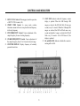
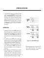
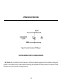
INSTRUCTION MANUAL MANUAL DE INSTRUCCIONES MODEL 4017A MODELO 4017A 10 MHz SWEEP FUNCTION GENERATOR with DIGITAL DISPLAY 10MHz GENERADOR DE BARRIDO/FUNCIONES CON EXHIBICION DIGITAL TEST INSTRUMENT SAFETY WARNING Normal use of test equipment exposes you to a certain amount of danger from electrical shock because testing must sometimes b e performed where exposed voltage is present. An electrical shock causing 10 milliamps of current to pass through the heart wil l stop most human heartbeats. Voltage as low as 35 volts dc or ac rms should be considered dangerous and hazardous since it can produce a lethal current under certain conditions. Higher voltages pose an even greater threat because such voltage can more easily produce a lethal current. Your normal work habits should include all accepted practices to prevent co ntact with exposed high voltage, and to steer current away from your heart in case of accidental contact with a high voltage. You will significantly reduce the risk factor if you know and observe the following safety precautions: 1. Don't expose high voltage needlessly. Remove housings and covers only when necessary. Turn off equipment while making test connections in high-voltage circuits. Discharge high-voltage capacitors after removing power. 2. If possible, familiarize yourself with the equipment being tested and the location of its hi gh voltage points. However, remember that high voltage may appear at unexpected points in defective equipment. 3. Use an insulated floor material or a large, insulated floor mat to stand on, and an insulated work surface on which to place equipment; and make certain such surfaces are not damp or wet. 4. Use the time proven "one hand in the pocket" technique while handling an instrument probe. Be particularly careful to avoid contacting a nearby metal object that could provide a good ground return path. 5. When testing ac powered equipment, remember that ac line voltage is usually present on some power input cir cuits such as the onoff switch, fuses, power transformer, etc. any time the equipment is connected to an ac outlet, even if the equipment is turned off. (continued on inside back cover) 1 Instruction Manual for Model 4017A 10 MHz SWEEP/FUNCTION GENERATOR with Digital Display 22820 Savi Ranch Parkway • Yorba Linda • CA 92887-4610 Phone: (714) 921-9095 • Fax: (714) 921-6422 • www.bkprecision.com 2 TABLE OF CONTENTS Page Page TEST INSTRUMENT SAFETY ................ inside front cover MAINTENANCE............................................................ 15 INTRODUCTION ............................................................. 4 Fuse Replacement ........................................................... 15 SPECIFICATIONS ........................................................... 5 Instrument Repair Service ............................................... 15 CONTROLS AND INDICATORS...................................... 7 CUSTOMER SUPPORT.................................................. 16 OPERATING INSTRUCTIONS ......................................... 9 WARRANTY SERVICE INSTRUCTIONS ...................... 17 Frequency and Waveform Selection ................................... 9 LIMITED TWO-YEAR WARRANTY ............................. 18 Considerations ................................................................ 10 SPANISH MANUAL ...................................................... 20 Duty Cycle Control ......................................................... 11 TTL/CMOS Output ......................................................... 12 Sweep Operation ............................................................. 12 Voltage Controlled Frequency Operation .......................... 13 Output Protection Considerations ..................................... 13 Function Generator Applications Guidebook .................... 14 3 INTRODUCTION triangle waves over the 0.1Hz to 10MHz range. This encompasses subaudible, audio, ultrasonic, and RF applications. A continuously variable dc offset allows the output to be injected directly into circuits at the correct bias level. The B+K Precision Model 4017A Sweep/Function Generator is a versatile signal source which combines several functions into one unit - waveform generation, pulse generation (through variable symmetry), and frequency sweep. Additionally, the instrument provides the added convenience of a built-in frequency counter. This permits more accurate determination of output frequency than is possible with a simple calibrated dial. Coarse and fine tuning controls permit precision settability of the output frequency. The sweep generator offers linear or log sweep with variable sweep rate and adjustable sweep time. Variable symmetry of the output waveform converts the instrument to a pulse generator capable of generating rectangular waves or pulses, ramp or sawtooth waves, and slewed sine waves. With this versatility, the unit has a vast number of applications in both analog and digital electronics in the engineering, manufacturing, servicing, educational, and hobbyist fields. In addition to the above features, an external voltage may be used to control operating frequency. This is useful in situations where an externally controlled frequency is desirable. The heart of the function generator is a VCG (voltagecontrolled generator) that produces precision sine, square, or 4 SPECIFICATIONS FREQUENCY CHARACTERISTICS Waveforms Sine, Square, Triangle, ± Pulse, ± Ramp Range Resolution Tuning Range Variable Duty Cycle Operating Modes Frequency Stability 0.1Hz to 10MHz in 8 ranges 5 digits Coarse: 10:1, Fine: ±5% of Coarse Setting 15:85:15 Continuously Variable Normal, Sweep, VCG Output will change less than 0.09% over 15 minutes after 1 hour warmup. OUTPUT CHARACTERISTICS Impedance 50Ω ±10% Level 20V p-p Open-circuit, 10V p-p into 50Ω Amplitude Control Variable, 20 dB range typical Attenuation -20dB ±1 dB DC Offset Preset: ±0.1V typical Variable: ±10V open-circuit, ±5V into 50 Ω SINE WAVE Distortion Flatness (into 50 Ω) 3% typical at 1kHz ±5% (.45 dB) 0.1Hz to 8MHz, ±20% (2.0 dB) 8MHz to 10MHz 5 SQUARE WAVE Symmetry Rise Time 0.1Hz to 100kHz ≤2% ≤30nS TRIANGLE WAVE Linearity ≥98% to 100kHz TTL OUTPUT Level Rise Time Duty Cycle 0.8V to 2.4V ≤20nS 50% typical CMOS OUTPUT Max Frequency Level Rise Time 2MHz 4V to 14V ±0.5V p-p, Continuously variable ≤120nS VCG (Voltage Controlled Generator) INPUT Input Voltage 0 - 10V ±1V causes a 100:1 frequency change Impedance 10kΩ ±5% SPECIFICATIONS SWEEP OPERATION Mode Width Rate Sweep Output LIN / LOG 100:1, Continuously variable 0.5 sec to 30 sec, continuously variable 0 to 10V FREQUENCY COUNTER Accuracy Time Base Accuracy ±1 count Time Base Accuracy ±10PPM (23 °C ±5 °C) Display 5 digit LED POWER SOURCE 120 / 230VAC ±10%, 50 / 60Hz, internal jumper selectable DIMENSIONS (H x W x D) 5.5 x 11.75 x 10.575” (140 x 298 x 264mm) WEIGHT 4.5 lbs. (2 kg) ACCESSORIES Output Cable, BNC to Alligator Clips Instruction Manual NOTE: See Maintenance section for AC Line Selection and fuse information. Specifications and information are subject to change without notice. Please visit www.bkprecision.com for the most current product information. 6 CONTROLS AND INDICATORS FRONT PANEL (Refer to Fig. 1) 1. 2. 3. 4. 5. 6. 7. 8. 9. 10. 11. 12. 13. 14. 15. 16. POWER Switch. Turns power on and off. RANGE Switch. Selects output frequency range. Seven ranges from 1 Hz to 10MHz. Switch indicates maximum frequency of range and is adjusted with COARSE FREQUENCY control to 0.1 times the maximum. For example, if the 100 kHz range is selected, the output frequency can be adjusted from 10kHz to 100kHz. FUNCTION Switch. Selects sine, square, or triangle waveform at OUTPUT jack. OUTPUT LEVEL Control. Controls the amplitude of the signal at the OUTPUT jack. Output level can be decreased by approximately 20 dB with this control. DC OFFSET Control. Enabled by the DC OFFSET Switch (14). Clockwise rotation from center changes the DC offset in a positive direction while counterclockwise rotation from center changes the DC off set in a negative direction. OUTPUT Jack. Waveform selected by FUNCTION switch as well as the superimposed DC OFFSET voltage is available at this jack. TTL/CMOS Jack. TTL or CMOS square wave, depending on the position of the CMOS LEVEL switch (15) is output at this jack. This output is independent of the OUTPUT LEVEL and DC OFFSET controls. CMOS LEVEL Control. Rotating this control clockwise increases the amplitude of the CMOS s quare wave at the TTL/CMOS jack. VCG/SWEEP Jack. Controlled by SWEEP EXT/INT Switch (12). When SWEEP EXT is selected, jack is the Voltage Controlled Generator input and permits external control of generator output frequency by a DC voltage input at this jack. A positive vol tage will decrease frequency. DUTY CYCLE Control. Enabled by the DUTY CYCLE Switch (17). Rotation from center position adjusts the duty cycle of the main OUTPUT signal. -20 dB Switch. When engaged, the signal at the OUTPUT jack is attenuated by 20dB. SWEEP INT/EXT Switch. When engaged (INT) enables the sweep mode of operation. Sweep rate is controlled by SWEEP TIME control (18) and sweep magnitude is controlled by the SWEEP WIDTH control (16). When released (EXT), allows external control of generator output frequency by a DC voltage input at the VCG/SWEEP jack (9). SWEEP LIN/LOG Switch. When engaged (LOG) selects logarithmic sweep characteristic and in the released (LIN) position selects a linear sweep characteristic. DC OFFSET Switch. When engaged, enables operation of the DC OFFSET control (5). CMOS LEVEL Switch. When engaged, changes the TTL signal to CMOS signal at the TTL/CMOS jack . SWEEP WIDTH Control. Rotation determines sweep width by adjusting sweep stop frequency. 7 CONTROLS AND INDICATORS 22. GATE LED. Indicates when the frequency counter display is updated. When the 100K through 10M ranges are selected, the LED will flash 10 times per second (every 0.1 seconds). When the 10 through 10K ranges are selected, the LED will flash once every second and when the 1 range is selected, the LED will flash every 10 seconds. As the LED turns off, the display is updated. 23. Hz and KHz LED. Indicates whether the counter is reading in Hz or kHz. 17. DUTY CYCLE Switch. When engaged, enables operation of DUTY CYCLE control (10). 18. SWEEP TIME Control. In sweep mode, rotation determines amount of time to sweep from the start frequency to the stop frequency. 19. FINE FREQUENCY Control. Vernier adjustment of the output frequency for ease of setting frequency. 20. COARSE FREQUENCY Control. Coarse adjustment of the output frequency from 0.1 to 1 times the selected range. 21. COUNTER DISPLAY. Displays frequency of internally generated waveform. 8 Figure 1. Model 4017A Front Panel. OPERATING INSTRUCTIONS The B+K Precision Model 4017A Sweep/Function Generator is a versatile instrument, capable of producing a variety of output waveforms over a broad range of frequencies. To gain a working familiarity with the unit, it is recommended that it be connected initially to an oscilloscope, so that the effects of the various controls on the output waveforms can be observed. Use this manual as required for reference until becoming accustomed to the operating procedures. FREQUENCY AND WAVEFORM SELECTION 1. Initially, verify that the DUTY CYCLE (17), CMOS LEVEL (15), DC OFFSET (14), -20 dB (11), and SWEEP INT/EXT (12) switches are in the OUT position (released). This will produce a symmetrical waveform unaffected by the sweep generator and other controls. 2. Plug the unit into an appropriate power source and turn it on by engaging the POWER switch (1). 3. Select the desired waveform (SINE, SQUARE, or TRIANGLE) by engaging one of the FUNCTION switches (3). Phase relationships of the waveforms are shown in Fig. 2. 4. Select the frequency of the waveform by depressing one of the RANGE switches (2). The output frequency is displayed, along with the appropriate measurement units, KHz or Hz (23), on the LED display. 5. Rotate the COARSE (20) frequency control to quickly set the output frequency to the approximate desired value. The FINE (19) frequency control can then be used to easily set the output to the specific desired value. The frequency selected is available at the OUTPUT jack (6). In addition, a digital signal, either TTL 9 or CMOS is available at the TTL/CMOS jack (7) (refer to the Figure 2. Output Waveform and Phase Relationship 6. Adjust the amplitude of the output as desired using the OUTPUT LEVEL control (4). Rotation of this control varies the amplitude from maximum to 20 dB below maximum. An additional attenuation of -20 dB is available by engaging the -20 dB switch (11). The attenuation factors can be combined for a total of -40 dB. The maximum signal level is 10 V p-p (into 50 Ω). OPERATING INSTRUCTIONS 7 . A superimposed DC component can be added to the output signal by engaging the DC OFFSET switch (14) to enable operation of the DC OFFSET control (5). Rotation of this control adds a positive or negative DC component to the output signal. The DC component introduced is independent of the OUTPUT LEVEL control and can be varied by ±10 volts open circuited or ±5 volts into 50 Ω. The DC Offset does not affect the TTL/CMOS output jack. The effect of DC OFFSET is shown in Fig. 3. CONSIDERATIONS 1. Counterclockwise rotation of the COARSE frequency control decreases the output frequency to approximately one-tenth of the maximum for the range selected (10:1). For example, if the 10K range is selected and the COARSE frequency control is set to full counterclockwise, the output frequency is approximately 1 kHz. 2. It is advisable to set the FINE frequency control to the approximate center of its rotation before setting the COARSE frequency control. This assures that the FINE control will not reach its limit while trying to finalize the frequency setting. 3. The FINE frequency control provides approximately ±5% frequency deviation from the COARSE control setting. This provides vernier adjustment to easily set the frequency to a precise value. 4. When the 1Hz range is selected, the gate time is 10 seconds and the display is updated once every 10 seconds. The result of a frequency change will not be displayed until 10 seconds later. Adjust the frequency in progressively smaller steps, waiting for 10 the display to update until the desired frequency is obtained. Figure 3. Use of DC OFFSET Control 5. When outputting square waves or when using the TTL output, terminate the cable into 50 Ω to minimize ringing. Also, keep cables as short as possible. OPERATING INSTRUCTIONS 6. Remember that the output signal swing of the generator is limited to ±10 volts open circuited or ±5 volts into 50 Ω, and applies to the combined peak-to-peak signal and DC offset. Clipping occurs slightly above these levels. Fig. 3 illustrates the various operating conditions encountered when using the DC offset. If the desired output signal is large or if a large DC offset is required, an oscilloscope should be used to make sure that the desired signal is obtained without undesirable clipping. DUTY CYCLE CONTROL The DUTY CYCLE control can be used to alter the symmetry of the output waveform, to produce waveshapes such as those shown in Fig. 4. For a square wave, symmetry variation amounts to changing the duty cycle (ratio of "high" to "low" time), effectively converting the instrument into a pulse generator. For a triangle wave, the result is a ramp, and with a sine wave, a distorted waveshape called a slewed sine is produced. The Model 4017A provides for symmetry variation from 15% to 85%. 1. Select the waveform desired either SINE, SQUARE or TRIANGLE. 2. Engage the DUTY CYCLE switch (17) and adjust the DUTY CYCLE control (10) for the desired waveshape. Clockwise rotation from center results in an increase in square wave duty cycle, and changes the sine and triangle waves as shown in the top waveform of each pair of Fig. 4. Counter-clockwise rotation results in the bottom waveform in each pair. 3. Varying the duty cycle setting results in a slight change11 in frequency. Adjust the COARSE and FINE frequency Figure 4. Effects of Symmetry Variation. OPERATING INSTRUCTIONS TTL/CMOS OUTPUT 1. The end frequency of the sweep (lowest frequency) can be adjusted by rotating the SWEEP WIDTH control (16). This adjustment should generally be made after setting the starting frequency, because it is largely dependent on that setting. The TTL/CMOS output jack provides a fast rise time square wave output. Either a fixed TTL or a variable CMOS output level is available. The output is positive with respect to ground and can be used as an external sync pulse for oscilloscopes or as a variable frequency signal source for exercising logic circuits. Because of the fast rise time of this output, cable length should be minimized to limit ringing and overshoot. 2. The front panel VCG/SWEEP jack (9) provides the internal ramp signal which can be used as the horizontal deflection signal for an oscilloscope, to give an X-Y display of signal amplitude vs. frequency. This method is commonly used when testing the frequency response of audio equipment or the bandwidth of amplifiers or other equipment. The response will be displayed high frequency to low frequency from left to right on the X-Y display. If the output of the circuit to be tested is connected to the vertical scope input, and the SWEEP output to the horizontal, setting the scope to X-Y mode produces the amplitude vs. frequency plot mentioned above. However, note that switching to LOG sweep still produces a linear display on the scope. This is because the horizontal sweeping signal, the internal log ramp, also becomes logarithmic when the sweep does. To view a true logarithmic graph, put the scope back in time base operation and use the Sweep output solely as a scope trigger. Use the scope's linear time base as a horizontal deflection source. 1. Select the desired frequency range and adjust the frequency controls as required. The OUTPUT LEVEL and DC OFFSET controls have no effect on the signal at the TTL/CMOS jack. 2. When the CMOS LEVEL switch (15) is OFF, a TTL signal is output at the TTL/CMOS jack. Select a CMOS signal by engaging the CMOS LEVEL switch and adjust the level of the signal by rotating the CMOS LEVEL control (8). SWEEP OPERATION 3. Select LINEAR sweep by leaving the SWEEP LIN/LOG switch (13) in the released position or LOG sweep by engaging the SWEEP LIN/LOG switch. VOLTAGE CONTROLLED FREQUENCY OPERATION 4. Set the starting frequency (highest frequency) of the sweep by adjusting the COARSE frequency control and observing the counter. 5. Engage the SWEEP EXT/INT switch (12). The duration of the sweep can be varied by adjusting the SWEEP TIME control (18). Sweep time is the same whether the sweep is linear or logarithmic, and is not affected by the sweep width. 12 The Model 4017A can be operated as a voltage-controlled generator by using an external control voltage applied to the VCG/SWEEP input jack. The externally applied voltage will vary the frequency which is preselected by the range switches and the frequency controls. Applying approximately +l0 V with the COARSE control at full clockwise decreases the output frequency by about 100 times (a 100:1 ratio). OPERATING INSTRUCTIONS 2. Set the starting frequency with the COARSE control. Apply a positive DC voltage to the VCG/SWEEP input jack (9) to decrease the frequency. A voltage from 0 to +10V will cause the frequency to decrease by a factor of 100 if the COARSE frequency control is set at maximum CW rotation. For example, if the starting frequency is 100kHz, applying +10V will change the output frequency to 1kHz. 3. To operate the function generator as a sweep generator, apply a positive going ramp signal to the VCG/SWEEP input jack. As the ramp voltage increases, the frequency decreases. The rate of sweep can be adjusted by varying the frequency of the ramp signal. 4. Specific frequencies can be selected by applying a fixed dc voltage to the VCG/SWEEP input jack or the frequencies can be stepped by applying a stepped dc voltage. 5. Do not apply more than ±15 volts (AC or DC + AC peak) to the VCG/SWEEP input jack. Inputs of more than 15 volts will not cause any further shift in the frequency and could cause damage to the generator. Damage of this type usually occurs by accidentally connecting the output of the function generator to a voltage in the equipment under test. The following protective measures are strongly recommended: 1. The user should understand the equipment under test well enough to identify valid signal injection points (i.e.: the base of a transistor, a logic input of a gate, etc.). The voltage at valid signal injection points is rarely high enough to damage the instrument. 2. If in doubt about the safety of a signal injection point, measure the voltage present at the intended point of signal injection before connecting the function generator output to that point. 3. When applying the main output of the function generator to a circuit point containing a dc level, adjust the DC OFFSET control so that the dc level at the main output matches the circuit voltage. 4. Connect the TTL output only to TTL-level circuits. Connect the CMOS output only to CMOS circuits. Measure the Vcc of the circuit under test and adjust the CMOS LEVEL control as instructed in the manual. 5. When the function generator is used by students or other inexperienced users, the circuit of Fig. 5 could be added into your TTL output probe or test clip set. It will protect the TTL output of the generator against external voltages up to ±20 volts. OUTPUT PROTECTION CONSIDERATIONS Use care when connecting the function generator output to a signal injection point. Excessive voltage at the point of signal injection of the function generator can cause internal damage. Under normal operation, the generator output should never be connected to an external voltage other than low dc values that can be matched with the DC OFFSET control. The Model 4017A is overload protected so that shorting the output, even continuously, will not cause damage. A fuse has been added in 13 OPERATING INSTRUCTIONS Figure 5. Circuit for Protection of TTL Output. FUNCTION GENERATOR APPLICATIONS GUIDEBOOK B+K Precision offers a “Guidebook to Function Generators” which describes numerous applications for this instrument, including hookup details. It also includes a glossary of function generator terminology and an explanation of function generator circuit op eration. It maybe downloaded for free off our website at www.bkprecision.com. 14 MAINTENANCE WARNING The following instructions are for use by qualified service personnel only. To avoid electrical shock, do not perform servicing other than contained in the operating instructions unless you are qualified to do so. INSTRUMENT REPAIR SERVICE Because of the specialized skills and test equipment required for instrument repair and calibration, many customers prefer to rely upon B+K PRECISION for this service. We maintain a network of B+K PRECISION authorized service agencies for this purpose. To use this service, even if the instrument is no longer under warranty, follow the instructions given in the WARRANTY SERVICE INSTRUCTIONS portion of this manual. There is a nominal charge for instruments out of warranty. Remember that ac line voltage is present on line voltage input circuits any time the instrument is plugged into an ac outlet, even if turned off. Always unplug the function generator before performing service procedures. AC LINE SELECTION This instrument can operate on 120 or 230 VAC source at 50 or 60 Hz. The internal jumper allows you to select the line voltage. Before connecting the power plug to an AC line outlet, be sure to check that voltage selector plug is set in the correct position corresponding to the line voltage in your location and the fuse rating is as shown in the table. Line Voltage 120V 230V Fuse 0.2 A 0.1 A FUSE REPLACEMENT 1. Locate the fuse holder on the input line receptacle. 2. Remove the fuse holder and replace the fuse with an equal value fuse 15 CUSTOMER SUPPORT 1-800-462-9832 B+K Precision offers courteous, professional technical support before and after the sale of their test instruments. The following services are typical of those available from our toll-free telephone number: Technical advice on the use of your instrument. Technical advice on special applications of your instrument. Technical advice on selecting the best instrument for a given task. Information on optional accessories for your instrument. Information on instrument repair and recalibration services. Replacement parts ordering. Availability of service publications. Information on other B +K Precision instruments. Requests for a new B+K Precision catalog. The name of your nearest B +K Precision distributor. Call toll-free 1-800-462-9832 Monday through Thursday, 8:00 A.M. to 5:00 P.M, Friday 8:00 A.M. TO 11:30 A.M. Pacific Standard Time 16 (Pacific Daylight Time summer) Service Information Warranty Service: Please return the product in the original packaging with proof of purchase to the address below. Clearly state in writing the performance problem and return any leads, probes, connectors and accessories that you are using with the device. Non-Warranty Service: Return the product in the original packaging to the address below. Clearly state in writing the performance problem and return any leads, probes, connectors and accessories that you are using with the device. Customers not on open account must include payment in the form of a money order or credit card. For the most current repair charges please visit www.bkprecision.com and click on “service/repair”. Return all merchandise to B&K Precision Corp. with pre-paid shipping. The flat-rate repair charge for Non-Warranty Service does not include return shipping. Return shipping to locations in North American is included for Warranty Service. For overnight shipments and non-North American shipping fees please contact B&K Precision Corp. B&K Precision Corp. 22820 Savi Ranch Parkway Yorba Linda, CA 92887 www.bkprecision.com 714-921-9095 Include with the returned instrument your complete return shipping address, contact name, phone number and description of problem. 17 Limited Two-Year Warranty B&K Precision Corp. warrants to the original purchaser that its products and the component parts thereof, will be free from defects in workmanship and materials for a period of two years from date of purchase. B&K Precision Corp. will, without charge, repair or replace, at its option, defective product or component parts. Returned product must be accompanied by proof of the purchase date in the form of a sales receipt. To obtain warranty coverage in the U.S.A., this product must be registered by completing a warranty registration form on www.bkprecision.com within fifteen (15) days of purchase. Exclusions: This warranty does not apply in the event of misuse or abuse of the product or as a result of unauthorized alterations or repairs. The warranty is void if the serial number is altered, defaced or removed. B&K Precision Corp. shall not be liable for any consequential damages, including without limitation damages resulting from loss of use. Some states do not allow limitations of incidental or consequential damages. So the above limitation or exclusion may not apply to you. This warranty gives you specific rights and you may have other rights, which vary from state-to-state. B&K Precision Corp. 22820 Savi Ranch Parkway Yorba Linda, CA 92887 www.bkprecision.com 18 714-921-9095 TEST INSTRUMENT SAFETY (continued from inside front cover) 6. Some equipment with a two-wire ac power cord, including some with polarized power plugs, is the “hot chassis” type. This includes most recent television receivers and audio equipment. A plastic or wooden cabinet insulates the chassis to protect the custom er. When the cabinet is removed for servicing, a serious shock hazard exists if the chassis is touched. Not on ly does this present a dangerous shock hazard, but damage to test instruments or the equipment under test may result from connecting the ground lead of most t est instruments to a “hot chassis”. To test “hot chassis” equipment, always connect an isolation transformer between the ac outlet and the equipment under test. The B+K Precision Model TR-110 or 1604 Isolation Transformer, or Model 1653 or 1655 AC Power Supply is suitable for most applications. To be on the safe side, treat all two-wire ac equipment as “hot-chassis” unless you are sure it has an isolated chassis or an earth ground chassis. 7. On test instruments or any equipment with a 3-wire ac power plug, use only a 3-wire outlet. This is a safety feature to keep the housing or other exposed elements at earth ground. 8. B+K Precision products are not authorized for use in any application involving direct contact between our product and the human body, or for use as a critical component in a life support device or system. Here, “direct contact” refers to any connection from or to our equipment via any cabling or switching means. A “critical component” is any component of a life support device or system whose failure to perform can be reasonably expected to cause failure of that device or system, or to affect its safety or effectiveness. 9. Never work alone. Someone should be nearby to render aid if necessary. Training in CPR (cardio -pulmonary resuscitation) first aid is highly recommended. 19 22820 Savi Ranch Parkway • Yorba Linda • CA 92887-4610 Phone: (714) 921-9095 • Fax: (714) 921-6422 • www.bkprecision.com © 2005 B+K Precision Printed in U.S.A. V050114 480-311-9-001 20