1
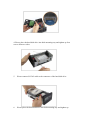
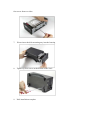
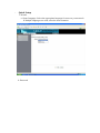
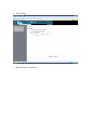
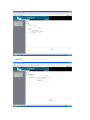
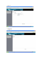
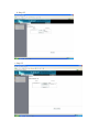
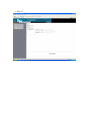
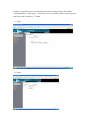
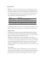
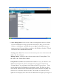
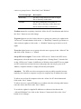
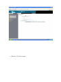
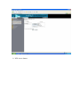
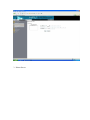
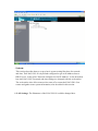
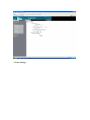
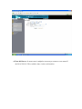
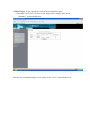
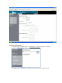
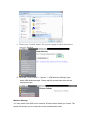
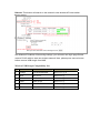
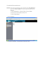
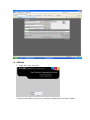
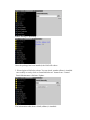
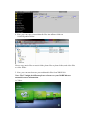
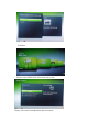
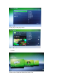
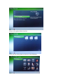
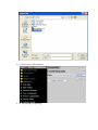
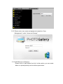
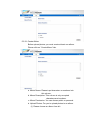
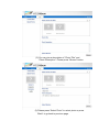
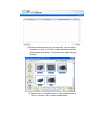
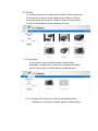
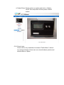
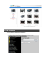
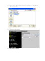
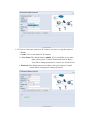
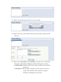
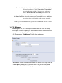
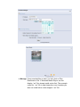
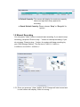
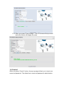
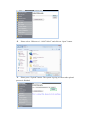
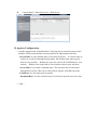
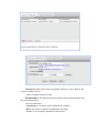
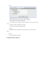
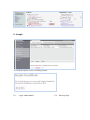
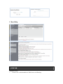
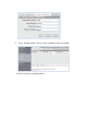
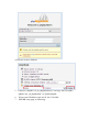
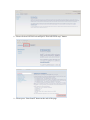
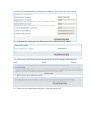
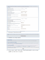
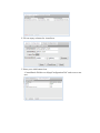
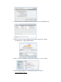
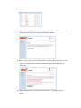
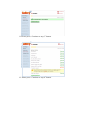
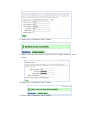
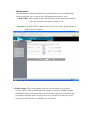
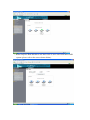
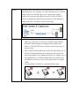
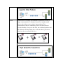
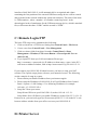
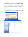
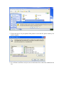
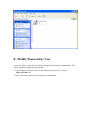
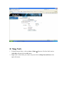
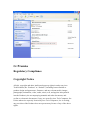
Model:I-NA312N1-S Network Attached Storage User Manual www.ineotechusa.com Content 1 Getting Started Product Specification……….. Networking Concept………. Package Contents …………………………...……. System Requirements ………………………….. Updating Your Operating System ……………… Handling Precautions…………………… 2 Setting Up I-NA305N1 Front View …………… The information on LCD…………….. Hard Disk Drive Installation………… 3 Connecting the NAS Connecting the Cables ………………. NAS Mode Enclosure Mode Powering Up the NAS ……..……… 4 Configuring the NAS Overview………. First Time Login………….. Basic Setup………….. Control Panel…………………… uShare Web Album IP Camera Web Server PHP BB Gallery 5 Appendixes A: Mount NFS share in Linux B: USB Devices C: Remote Login FTP D: Printer Server E: Modify Password by User F: Map NAS G: Promise 1. Getting Started FOREWORD Thank you for choosing ineo products. This user manual provides detailed instructions of usingI-NA312N1-S. Please read carefully and start to enjoy the design of intimate user interface ofI-NA312N1-S. Note 1. This manual provides the description of all functions ofI-NA312N1-S. The product you purchased may not support certain functions dedicated to specific models. 2. All features, functionality and other product specifications are subject to change without prior notice or obligation. 3. All brands and products names referred to are trademarks of their respective holders. LIMITED WARRANTY In no event shall the liability of ineo Tech Computers, Inc. ineo exceed the price paid for the product form direct, indirect, special, incidental, or consequential software, or its documentation. ineo makes no warranty or representation, expressed, implied, or statutory, with respect to its products or the contents or use of this documentation and all accompanying software, and specifically disclaims its quality, performance, merchantability, or fitness for any particular purpose. ineo reserves the right to revise or update its products, software, or documentation without obligation to notify any individual or entity. Attention: Please backup your system periodically to avoid any potential data loss. ineo disclaims any responsibility of all sorts of data loss or recovery. If you return any components ofI-NA312N1-S package for refund or maintenance, make sure they are carefully packed for shipping. Any form of damages due to improper packaging will not be compensated. Product Specification Chipset Solution Storlink 3516 ARM9 300MHz LAN Interface Data Transfer Rates: 10/100/1000 Mbps Connector Type: RJ-45 x 1port Internal Hard Drives Number of Drives: 2 Drive Interface: RJ-45 for SATA HDD Interface Standard Compliance: USB 2.0 Connector Type: USB Host A (Female) x 1 port Device: works with USB devices, like USB HUB, USB Printer, USB Enclosure, and USB Pen Drive. Supports USB printer server function File System Management EXT2 / EXT3 / FAT32 Networking Concept Language English, Traditional Chinese, Simplified Chinese System Tools System Firmware upgrades Reset system setting Display log file with SAMBA/FTP/DHCP server/system/Administration Support Hard Drive Capacity Up to Package 4TB (2TB xContents 2) Protocol Support Networking: TCP/IP File Sharing: SAMBA, FTP Management: HTTP User Management User account management (no limit) User group management (no limit) User can change password OS Supported (for Client PC) Microsoft Windows 98SE / NT / 2000 / XP / 2003 / Vista / 7 Linux Redhat / Fedora / SUSE Mac OS X Wireless Network (I-NA305N1 w/ WiFi Optional) Fixed / Dynamic IP Address DHCP Server Encryption with 128 bit WEP / WPA I/II IEEE 802.11 b/g/n Features Aluminum alloy casing with secure front door LCD Display Gigabit Transfer rate up to 1000Mbps Fully compatible with 3.5" SATA I/II HDD Support RAID 0/1 Function Truly Plug and Play Powerful and Quiet 40 x 40 mm Fan External Power Adapter Networking Concept I-NA305N1 LAN to SATA HDD w/o WiFi CD Yes RJ-45 Cable Yes Key Yes User Manual Yes Power Adapter Yes System Requirements Hardware ® Pentium II, 200 MHz equivalent or newer for IBM compatible PC ® PowerPC G4, 350 MHz or newer for PowerPC-based Apple Computer Core or newer for Intel-based Apple Computer Software Windows 98SE / 2000/ 2003 / XP / Vista / 7 ® Mac OS X Note: For highest performance and reliability, we recommend that you install the latest service pack (SP) and updates. Updating Your Operating System Windows Go to the Start menu and select Windows updates. For more information regarding updating your system, visit http://windowsupdate.microsoft.com. Macintosh Go to the Apple menu and select Software Update. For more information regarding updating your system, visit http://www.apple.com/macosx. Handling Precautions Our products are precision instruments and must be handled with care during unpacking and installation. Drives may be damaged by rough handling, shock, or vibration. Be aware of the following precautions when unpacking your external storage kit: Do not unpack the product until you are ready to install it. Do not drop or jolt the product. Do not move the external storage when it is powered up. 2. Setting Up You will need one or two 3.5 inch SATA Hard Disk Drives. Carefully follow the procedures to install the Hard Disk Drives into the NAS System. ineo |I-NA312N1-S Front View The Information on LCD Hard Disk Drive Installation 1. Loosen four screws from the bottom of the NAS 2. Please pull out the disk mounting tray from housing 3. Please connect SATA1 cable to the larger size hard disk drive (Install two SATA hard disk drives into the SATA Connectors on the disk mounting trays. If the hard disk driver does not have the same size, please place the lager hard disk drive to SATA1 cable. If you format HDD separately, the operating system only can identify the HDD connect to SATA1 cable) 4. Please place the hard disk drive into disk mounting tray and tighten up four screws from two sides 5. Please connect SATA2 cable to the connector of the hard disk drive 6. Please place the hard disk drive into disk mounting tray and tighten up four screw from two sides 7. Please insert the disk mounting tray into the housing 8. Tighten up four screws at the bottom of the NAS 9. NAS installation complete 3. Connecting the NAS Connecting the Cables 1. Connect the Power Adapter to DC IN. 2. Connect one end of the RJ-45 cable to the Ethernet port at the rear of the NAS. 3. Connect the other end of the RJ-45 cable to an available Ethernet port on your computer or router. Powering Up the NAS Press the power switch to turn on the unit. Wait 3 seconds after blue LCD illuminates. 4. Configuring the NAS Overview All administrative tasks are performed through this web utility. The web utility can be accessed by any PC on the network by entering http://192.168.1.1 or http://stornas/ (stornas is the default hostname) in the PC’s web browser Address window. If your NAS is behind a router, you can get the IP address from the LCD panel onI-NA312N1-S. First Time Login 1. Startup Browser and link to http://192.168.1.1 2. The default account is “admin” and password is “admin”. 3. After the login, please format hard disk drives first. (Please reference: Control Panel > Maintenance > Disk Utility). 4. In order to setup the system, please restartI-NA312N1-S, and login to web utility. Basic Setup - Quick Setup 1. Wizard: a. Setup Language: Select the appropriate language for users on your network. If multiple languages are used, select the most common. b. Password c. Hostname Setting: In this field, you can enter a new Hostname for the NAS Link. Punctuation and some special characters can not be used in the name. d. Internet Protocol Setting e. Time Settings f. Wizard Setting Confirmation. 2. Add User a. Step 1/3: Attention: To be able to set a quote the EXT2 or EXT3 file system has to be chosen for the data partition, because only the EXT2 or EXT3 file system supports that feature. If the data partition is formatted with FAT32, this option cannot be selected. b. Step 2/3: c. Step 3/3: 3. Add Group: a. Step 1/3 b. Step 2/3 c. Step 3/3 4. Add Share: a. Step 1/3 b. Step 2/3 c. Step 3/3 Control Panel - Users and Groups: In order to be able to control the Network access on the NAS, theI-NA312N1-S is able to setup access restrictions for user and group definitions. A user is a personal identifier authenticated by a password or a user can be part of one or more groups. So access rights can be defined for users or groups. 1. User Management: To create a new user simply fill out the form and click the “Save” button. The next example shows a procedure setting up a new user with the user name “aa” and the password “aa”. The user should also have a private folder, which is a special folder just for his private use, which is only accessible or even displayed by the one who identifies with that particular username and password. In addition, the disk space that the user can use should be limited to a maximum of 1TB, so we set a quota. Attention: To be able to set a quote the EXT2 or EXT3 file system has to be chosen for the data partition, because only the EXT2 or EXT3 file system supports that feature. If the data partition is formatted with FAT32, this option can not be selected. . a. Step 1/2: b. Step 2/2: After having clicked on the “Save” button, the user account and the personal folder is created. Also the Samba network share (expression of the personal folder to the network) has been created and can be accessed using the username and password which has been defined. The personal folder and the Samba network share have the same name as the username defined. 2. Group Management: To create a new group, it is just necessary to enter the group name and click on the “Save” button. To delete one or more group, mark them in the “Existing Groups” list and click on the “Delete Group” button. To add one or more Users to a Group you do not need to open each User one by one to add them to a group. When you select the Group you want the users to be added to in the “Exiting Groups” List, click on the “Members” button and select the users you wish to add to the selected group. To remove one or several user from a particular group you also just have to select the Group you want the users to be deleted from in the “Exiting Groups” list and the “Group Members” form opens. Select the users you want to remove from the group and click on the “Remove>>” button. a. Step 1: b. Step2: - File and Print 1. File Server: A file server offers disk space to a network. The term server used to name a service offered to the network.I-NA312N1-S uses three different services to provide hard disk space to the network: Samba (Windows), FTP and NFS. The basic settings regarding these three services are done in the “File Server” item of the “File” submenu. All three servers could be disabled separately. The “File Server Setting” form is structured into four parts: Section Description Windows Setting Basic settings for the Samba service FTP Server Setting Basic settings for the FTP service settings NFS Server Setting Basic settings for the NFS service Guest Access Setting Basic settings for the cross services guest account By enabling the “Enable” checkmark for each section the corresponding service is enabled or disabled. By default all services are enabled to grant a rapid start up. Windows Setting The Samba server provides the storage for Windows client, also MAC OS and Linux computers are able to use network storage via this service. It has the most complex structure and provides the most features; therefore, the basic settings are a little more extensive, than those for the other services. Windows offers possibility to structure network participants in so called “Workgroups”. Via this identifier – which is just a name – it gives the opportunity to assort logical units of network participants to give a better overview. This could be set up in the referring field on the form. Also you can enter a description term which will be displayed when browsing the windows network. If the windows network has a WINS server for providing a network directory, the IP Address could be specified here. Server Settings Aside of the possibility to enable or disable the FTP service, the port number of that server could be modified in order to accommodate a possible port forwarding of a internet access router which uses NAT, for example if it is desired to make twoI-NA312N1-S accessible via port forwarding by an internet access router. Attention: Changing the FTP servers port from 21 (default) to another value will cause, that standard FTP client will not be able to access theI-NA312N1-S FTP server, except the changed port number is configured in the FTP client appropriately. NFS Server Setting Here the NFS Server can be enabled or disabled. Guest Access Setting By default, theI-NA312N1-S has a preconfigured account for guest access respectively--anonymous access. This means that via Windows share and FTP there is a guest folder/share which could be accessed anonymously without a user/password authentication. Attention: Leaving the guest access enabled means a high level security risk when theI-NA312N1-S is exposed to the internet or any public network. This can lead to malicious abuse. If you expose theI-NA312N1-S to any public network, it is strongly recommended to disable the Guest Access. The reason why the default setting is enabled is to ensure that theI-NA312N1-S is readily accessible when used the first time. In addition to enabling and disabling that feature a Quota for that account could be defined for restricting the quantity of disk used by users accessing theI-NA312N1-S via guest settings. Attention: To be able to set a quote the EXT2 or EXT3 file system has to be chosen for the data partition, because only the EXT2 or EXT3 file system supports that feature. If the data partition is formatted with FAT32, this option can not be selected. To save changes been made please click on the “Save” button. Character Set drop down list is for support multi-languages. If you prefer upload a file name other than English, you can change the default language to your file name’s language to avoid the file name display as garbage characters. 2. Share Management: In this section of the web management surface is defined how the hard disk drive storage is offered to the network. Here you can create folders, so called shares, and define the access rights for the different users or groups towards it. For each folder created here--the Windows (Samba), FTP and NFS Access can be defined and restricted. Creating a new share: To create a new share name please enter a share name and click on the “Save” button. Deleting a share: To delete a share select the share in the “Existing Shares” list and click on the “Delete Share” button. Setup Windows, FTP access restriction for a share: To setup the Windows and FTP access restriction for a share, select the share you wish to restrict in the “Existing Shares” list and change to the Windows and FTP access form. There are two major ways of defining the access towards a share. The first is to allow access for all. Then no access control takes place on the share and everybody can read/write or even deletes data on the share. The second is to define the access rights on user and group level. There are two different access rights you can give to a user or a group of users: “Read Only” and “Writable”. User/Group right Description Read Only The user is only allowed to read or copy a file or directory on the share. Writable The user is allowed to read, write or delete a file or directory on the share and also to create new files or directories. To allow access for everybody, check the “Allow for all” check button and click on the “Save” button to save this change. To grant rights on user level select the user or group you want to give rights in the “No Access” list and whether click on the “<< Read Only” button to give him/er or it the read only rights or click on the “<< Writable” button to give him/er or it all rights. To revoke rights from a user or group select the user or group in the “Allowed” list and click on the “Remove >>” button. Set up NFS access rights: To access the “NFS Access” form for the NFS access management, select the share to be managed in the “Exiting Shares” list and click on the “NFS Access” button. In difference to Windows share and FTP access rights are NFS restrictions not based on users and groups but can only be given to IP Address, complete Subnets or simply all network participants. Attention: The NFS server does not grant security on public networks because anybody who controls a computer can give its computer any IP Address he wants. To allow access from all computers select the “Allow for all” check button and click on the “Save” button. To allow access to a special IP address or a subnet select the referring radio button, enter the values and click on the “Save” button. To revoke the rights for singular IP Addresses or subnets select them in the “Allowed IP/Subnet” list, click on the “Remove” button and click on the “Save” button to save changes. a. Windows, FTP Access button b. NFS Access button 3. Printer Server - System: This section describes how to set up a basic system setting like those for network and time. TheI-NA312N1-S is by default configured to get its IP Address from a DHCP server. In the point “Network configured on fix IP-Address” is also described how theI-NA312N1-S network and time settings are changed with the web surface. The web surface also offers some tools to turn off or restart theI-NA312N1-S on remote and gather some system information, also described in this section. 1. LAN Settings: The Hostname of theI-NA312N1-S could be changed here. 2. Wireless Settings: To enable wireless, check the option of “Wireless Enabled” and change the “SSID” & “Wireless Mode”, and then click on “Save” button. 3. Time Settings 4. Turn Off Server: In some cases it might be necessary to restart or even turn off theI-NA312N1-S. This could be done via the web interface. 5. Information: To display some basic system information. 6. Disk Usages: To get a quick overview of the used and free space. a. Summary: For a brief overview on the usage of the complete disk, select “Summary” as described below. b. User: For a detailed listing per user, please select “User” as described below. 7. Error Notification: To check the “Disk Usage”, when the usage of disk approach 90%, the system will notify administrator. To check the “Windows File Sharing Server”, the system will notify administrator when there is any problem. To check the “FTP Server”, the system will notify administrator when the FTP Server goes wrong. To check “DHCP Server”, the system will notify administrator when the DHCP Server suffer any problem. The “Check Interval” can be setup as hourly or daily. 8. Wireless USB dongle A. Login NAS > Control Panel > Maintenance > Software Update > Browse… B. Please select “UsbWifi-1.0.2_090716.bz2” and click on “Open” button C. Please press “Upload” button. The system is going to reboot after upload process is finished. D. Go to the "Control Panel” > “System” > “USB Wireless Settings" page Insert USB Wireless dongle. Please wait 30 seconds later then see the setting web page. Wireless Settings: You may double-click SSID on the wireless AP base station which you choose. The system will prompt you to choose the correct authentication mode. Refresh: This button will search on the network's new wireless AP base station. Set Wireless IP Address: After saving settings, you will enter new login page.Please remove RJ-45 cable to start use wireless network. Now, please press remove button before remove USB dongle from NAS. Wireless USB Dongle Compatibility List No Brand Model Name Note. 1 Corega CG-WLUSB2GNR 802.11 b / g / n 2 Asus WL-167G 802.11 b / g 3 D-link DWA-110 802.11 b / g 4 D-link DWL-G122 802.11 b / g 5 Buffalo WLI-UC-G300N 802.11 b / g / n 6 PCI GW-US300MiniW 802.11 b / g / n Network Service 1. DHCP Server: To enable DHCP Server, please check “Enable Server” option. To setup DHCP IP Address Start or End, please input the IP Address into the field. To setup the maximum lease time from one hour to one week, please choose from drop down list. 2. Bonjour 3. TorrentFlux(BT Download Function) Attention: To be able use this function, please upload the file of TorrentFlux.bz2 from CD to Software Update. The step for upload TorrentFlux.bz2 as following: 1. Click on Maintenance > Software Update > Browser Button 2. Choose the file of TorrentFlux.bz2 from CD 3. Click on Upload button a. Link to bt Button b. TorrentFlux Login Page: “Username:mysql / Password:123456” 4. uShare 1. Login NAS from web page. 2. Please install uShare page from Control Panel>Maintenance>Software Update uShare Package is uploading…. Once the package has been installed, the NAS will reboot. 3. Please login to NAS after reboot. You can check weather uShare is installed successfully or not by click on “Installed Software” button from “Control Panel>Maintenance>Software Update. The information table shows uNAS (uShare) is installed. 4. Now, you can copy your multimedia files into uShare folder on \\NAS-IP\public\media\ Please copy music files to music folder, photo files to photo folder, and video files to video folder. 5. Now, you can start browser your multimedia files from XBOX360. Note: The UI might be different please reference to your XOBX360 user manual for more information. A. Video: Select UPnP_NAS3000 from source list. Press Video folder. Select one of video from list and play the video. B. Music: Please select UPnP NAS 3000 from source list. Please select one of method from list to browser. Press play to start play music. C. Photo: Please select UPnP NAS3000 from source list. Please select photo folder from list. Now, you can select photo to browse or run slideshow. 5. Web Album 5.1 Web Album Software Installation 5.1.1. Please click on Control Panel > Maintenance > Software Update 5.1.2. Please click on “Browse” button and choose “Web_Album” from CD then click on Open button. 5.1.3. Please press Upload button 5.1.4. The package is uploading 5.1.5. After system reboot, you can click on Installed Software button to check the application is installed correctly. 5.2 Start Web Album 5.2.1 Please click on Control Panel > Network Service > Web Album. If default album port is using by your system, please change an available port web album. Please press “Enter Album” button to jump to web album. 5.2.2 Please enter user name and password created by “User Management” under “Users and Groups”. 5.2.3 Add Album(s) or Photo(s) Please click on “Add” button from link. In this section, you can create album or upload photo(s) and set album permission. 5.2.3.1 Create Album Before upload photos you must create at least one album. Please click on “Create Album” tab. a. Album Name: Please input characters or numbers into this column. b. Album Description: This column is only accepted characters and numbers. c. Album Permission: You can choose public or personal. d. Upload Photos: For you to upload photos to an album. (1) Please choose an album from lsit. (2) You can give a description of “Photo Title” and “Photo Description”. Please press “Browse” button. (3) Please press “Select Photo” to select photo or press “Back” to go back to previous page. (4) Please choose photo from your computer. You can select one photo or click on “Ctrl+A” to select all photos and then please press open button. The photos only support jpg, gif and png. (5) Please click on “Upload” button to start upload photos or click on “remove” link to cancel upload photo. (6) When all of photos upload to web album, the screen will display “Upload Finish…!!”. Note: *. Upload Limitation: Max. 10MB *. All of the upload pictures will be compressed twice. For the first time compression, the resolution of the picture is 520X480 and the resolution of the second time compression is 120X100. *. File limitation: It is depend on the capacity of hard disk drive. 5.2.4 Public You can search photo or album in this section. Please input part of file name into search column and choose “Album or Photo” from drop down list then press “Search” button to start search. The result will display on right hand side column. 5.2.5 Personal In this section, you can delete album, modify album description, modify photo, modify info, set photo as album cover, move photo to another album and delete photo. 5.2.5.1 Please click a photo from list to start browse photo. Besides, you can press “Delete” button to delete album. 5.2.5.2 a. Modify Info: You can type a short note for the photo in “Description” column and choose “Modify Info” from drop down list then press “Submit” button. b. Set as Cover: After you choose the photo from list, you can click on “Set as Cover” from drop down list and press “Submit” button. c. Change Album: You can move the photo to another album. First, select a photo and click on “Change Album” from drop down list and click on album from list. d. Delete Photo: Please select one photo and click on “Delete Photo” from drop down list and press “Submit” button. 5.2.6 Guest Login Guest user is only authorities to browser “Public Album” without any setup privileges. Guest user can view all albums, photos and search album or photo. 6. IP Camera 1.1 Surveillance Software Installation 1.1.1. Please click on Control Panel > Maintenance > Software Update 1.1.2. Please click on “Browse” button and choose “Survillance-1.6” from CD then click on Open button. 1.1.3. Please press Upload button 1.1.4. The package is uploading 1.1.5. After system reboot, you can click on Installed Software button to check the application is installed correctly. 1. 2. IP Camera’s Control Panel 1.2.1 Please follow the user manual of IP Camera to install IP Camera. After the IP Camera has been setup correctly, please click on the link under “Control Panel > Network Service > Surveillance” or type http://NAS-IP-Address:5001, for example http://192.168.1.179:5001 on address link of browser. When you click on the drop down list of IP, the system will detect IP Camera automatically. 1.2.2 If you are first time connect to IP Camera, you have to setup the required columns. a. Name: Give a nick name for IP Camera. b. User Name: The default name is admin. If you would like to use other name, please press “Control” button and click on Basic > User link to change password or create a new General User. c. Password: The default password is admin. Also you can press Control button link to setup page to change password. d. IP: Once the IP Camera connects correctly, the user just click on drop down list, the system will automatically detect IP address. e. Profile Use: After you setup schedule, you can choose one of the schedules from drop down list. f. Port: The default port number is 80. We strongly suggested that use default port number unless this port number has already been occupied by another application. g. Remark: This column is for you to write note for IP Camera, and this is not required column. After the required values has been input to correspond fields, please press “Save” button to save the value. 1.3. Arrange Schedule Profile This sub menu displays the scheduled profile(s). To customize the profile, click Add and enter a description for the profile in the prompt dialog window. Press OK to add it to the Schedule Profiles list. Press Delete button to delete the selected profile from the list. 1.3.1 Please press “Schedule” button to start setup process. 1.3.2 Please click on “Add” button to enter profile name, or press “BACK” link from right up corner to go back to previous page. 1.3.3 Please enter profile name and click on “Save” button. 1.3.4 Please select one of the schedule names from list and the setup menu will show up. 1.3.5 Please input “Start Time” and “End Time” and choose one of weekdays then press “Add” button. Finally press “Save” button to save values. a. Profile Name: Display profile name(s) that you added to the schedule profiles list. b. Weekdays: Select the day(s), Monday to Friday, which you want to assign in the schedule profile separately. Assigned weekday(s) will display in green color. c. Time List: Display the period of time that you have assigned within the selected weekday(s). Click “Copy this to all weekdays” to assign the same period of time to every weekday(s). Press “Delete this from all weekdays” to remove the selected period from every weekday(s). d. Start/End Time: Enter the start and end time and then press Add button to assign a time period within in the selected weekday. When you finish schedule setup, please click on “BACK” link to go back to main page. 1.4. File Manager File Manager is for you to manage recorded files. The user can setup “Time Span”, “Default Capacity for Surveillance Record” and choose the way how to deal with when the capacity is running out. 1.4.1 Please press “File Manager” button from main page. a. IP Camera: Please choose an available IP Camera from drop down list. b. Time Span: Please input a period of time to the column and press “Search” button to query recorded files. c. Manage: If any recorded files in here, you can click on Play, Download or Del. If Windows Media Player can not display “.avi” file, please install codec first. The example codec for “.avi” file is http://www.divx.com/, besides you also can install other codec support “.avi” file. d. Default Capacity: The screen will display the maximum capacity. Users can input how many spaces for recording. e. Reach Default Capacity: Please choose “Stop” or “Recycle” for system. 1.5 Manual Recording You can press “Video” button to manual start recording. If you want to stop recording, just press “Press to stop…” button to interrupt recording. If you do not press “Press to stop…” button, the system will keep recording by your “NAS Storage Setting”. The file size is “MPEG4: 300KB/sec, 630MB/hour and MJPEG: 400KB/sec”. 1.5.1 Once you press on “Video” button, the IP Camera will start record and in note column will display “Video is running….”. 1.5.2 When you press “Press to Stop…”, the IP Camera will stop record and note column will display file name. 1.6 Control When you press “Control” button, the pup up page will ask you to input user name and password. The default user name and password is admin/admin. For more information about “Control”, please reference to the user manual of IP Camera. 7. Web Server A. Web Server Installation 1. Login NAS > Control Panel > Maintenance > Software Update > Browse… 2. Please select “Webserver-1.1-090710.bz2” and click on “Open” button 3. Please press “Upload” button. The system is going to reboot after upload process is finished. 4. Control Panel > Network Service > Web Server B. Apache Configuration 1. Apache support multi virtual machines. This page shows currently setup virtual machine. Each virtual machine can be treated as an independent web host. 。ServerName: It is the domain name of currently web host. If a client wants to connect to a web host through domain name, the domain name must register from service provider. Besides, the user also can use IP+PortNumber to visit website. Double click on the link of ServerName to direct open web host. 。ServerAlias: It is an alias of domain name. The web host also can be found through Server Alias. This service also needs to register from DNS provider. 。ListenPort: It is the listen port for apache. 。DocumentRoot : It is the root directory of web host to provide user store data. 1. Add: 。 Listen port: Please fill out the port number and press “Save” button. The system is going to notice if the port number has been used. 。 DocumentRoot: The drop down list is going to list all shared folders and the second drop down list is root directory. 。 ClearForm: It is used for clear all data in the column. 。 Back: It is return to apache Configuration web page. 。 Access: It is to setup the attributes of directories. 2. Update: 。 Choose any ServerName from table and press Update button. 。ServerName and ServerAlias can be modified. 。 Listen port can NOT modify because the port number is listening. 。 DocumentRoot also can be modified. 3. Delete: 。Delete Virtual Machine: The delete function is only removing setup values but not delete directories and files. C. MySQL Configuration 1. MySQL Configuration page is displaying host address and user name. 2. Add: 。Administrator Name: The user name of administrator. 。Host Allowed: The host name allows connect to MySQL. 。Password: The password of login database. 。Save: When press save button, the system is going to verify user name is used or not. 。ClearForm: Remove all data in the columns. 。Back: Return to Mysql Configuration page. 3. Update: Root and localhost is default user and account name. It cannot modify or delete. 4. Delete: Root and localhost cannot delete. D. phpMyAdmin Login Page Default User Name: root / Password: 123456 Create new database Create the new database name display on left hand column E. Sample To verify the apache server is working normal. E-1、 Login: admin/admin E-2、Message Page F. Read Help 8. PHP BB Installation Step: 1、 Create a new virtual machine in Web Server as following: Note: The folder name is going to create after user gives the name in DocumentRoot. 2、 Please select the writeable check box. 3、When apache server is created, please go to “Mysql Configuration” page to create a user as following: 4、 Press “phpMyAdmin” link to create a database named as phpbb. 4-1 Please login in to phpMyAdmin 4-2 Please create a database 5、Compress “phpbb3.0.4_zh_phpbbchina.zip” and copy the files under “phpbb3.0.4_zh_phpbbchina” to \\public\phpbb\. 6、 Please enter IP address such as192.168.1.30:8090. 7、 PHP BB setup page as following: 8、Please click on INSTALL tab and press “Proceed to next step” button. 9、Please press “Start Install” button at the end of the page. 10、Please fill out database configuration and press “Proceed to next step” button. The “database server port” column accepts empty value. 11、The connection test is successful. Please press “Proceed to next step” button. 12、Please fill out administrator configuration and press “Proceed to next step” button. 13、Administrator setting pass test. Please press “Proceed to next step” button. 14、Please press “Download” button and upload the file following the instruction and press “Done” 15、Please press “Proceed to next step”. 16、Please browse to the bottom and press “Proceed to next step”. button. 17、Please press “Proceed to next step”. 18、PHP BB is successfully installed. 19、Please rename “install” folder under \\NAS-IP\public\phpbb\ in order to login phpBB. Any folder name is acceptable. 20、Please input IP address to the link of browser. 9. Gallery A. Gallery Installation 1. Please press “Add” button from “Control Panel>Network Service>Web Server>Add 2. Fill out empty columns for virtual host 3. Please press Add button from “ControlPanel>WebServer>MysqlConfiguration Tab” and create a new user. 4. Please create a new database named “gallery” by press phpMyAdmin . 5. Please use the user name and password which created from “Mysql Configuration” to login phpMyAdmin. 6. Please create new database called gallery and press “Create” button. 7. Please compress gallery-2.3-full.zip and copy all of data to \\NAS-IP\Public\Gallery. 8. Please input http://NAS_IP:PortNumber (ex:192.168.1.165:8091) to address link on browser and press “Begin Installation” button. 9. Please create a new text file called login.txt in the gallery directory on your web server and it must contain the randomly generated characters as following. 10. When authentication is successful, please press “Continue to step 2” button. 11. Please press “Continue to step 3” button. 12. Please press “Continue to step 4” button. 13. Please press save button. 14. Please press “Continue to step 5”. 15. Please fill out empty columns and press save button. 16. Please press “Continue to step 6” button. 17. Please enter the user name and password for admin and press create button. 18. Please press “Continue to step 7” button. 19. Please press “Continue to step 8” button. 20. Please press “Continue to step 9” button. 21. Please press “Activate Selected Modules” button. 22. Please press “Continue to step 10” button. 23. Please press “Continue to step 11” button. 24. Please press “Continue to step11” button. 25. Please press “Go to my Gallery” button. - Maintenance: The Maintenance submenu bundles tools for the hard disk setup, RAID setting, firmware upgrade, save or restore the configuration and a factory reset. 1. Disk Utility: When adding a new hard disk drive, please format the hard disk drive fist, and users can choose encrypt or not. Attention: The EXT2/EXT3 supports user level access control, but the format of FAT32 does not support. 2. RAID Setting: This screen display when only one hard disk drive connects toI-NA312N1-S, and for RAID function must have at least two HDDs. Besides, only RAID1 and Linear mode support enclosure mode, the mode of RAID 0 does not support enclosure mode. If you prefer to use your NAS as enclosure, please format your hard disk drives as RAID1 or Linear mode. * When setup two hard disk drives toI-NA312N1-S, users can create their RAID system (please refer to the screen shown below). RAID 0 RAID 1 Under this mode, the capacity of the hard disk drive is sum of two hard disk drives. For example, one of the hard disk drive is 250GB and the other one is 80GB, after create a single large virtual partition, the capacity under RAID 0 mode is around 302GB. It offers no redundancy, and therefore decreases overall reliability: a single disk failure will knock out the whole thing. 1. RAID 1 is also referred to as mirroring. Two partitions, all of the same size, each store an exact copy of all data, disk-block by disk-block. Mirroring gives strong protection against disk failure: if one disk fails, there is another with an exact copy of the same data. 2. Please install two hard disk drives with same model and size. If the sizes of the hard disk drives are different, the system will choose the smaller size to build raid system. For example, one of the hard disk drive is 250GB, and the other one is 80GB, after build RAID 1 system, the size of the hard disk drive is around 78GB. 3. The rebuild time for RAID 1 is around 80GB per hour. Linear RAID-Linear is a simple concatenation of partitions to create a larger virtual partition. It is handy if you have a number small drives, and wish to create a single, large partition. This concatenation offers no redundancy, and in fact decreases the overall reliability: if any one disk fails, the combined partition will fail. When the first hard disk drive is full, the data is just start to write into the second hard disk drive. 3. Firmware Upgrade:I-NA312N1-S is constructed to allow a complete upgrade for the firmware. The upgrade starts by selecting the upgrade file, which has to be located on the local hard disk. By clicking on the “Browse…” button a dialog pops up where you are able to select the file. When having selected please click on the “Start Upgrade” button and the upgrade process starts by uploading the upgrade file, followed by process of initialization. Attention: The firmware upgrade process might take up to 15 minutes. This process must not be interrupted. Please make sure that the power supply is not turned off until the upgrade process is completed. Attention: Please save all data and configuration externally before performing an upgrade! Pay attention to all remarks along the upgrade file! When the firmware upgrade process is finished,I-NA312N1-S restarts and the web browser window automatically switches to the start form. 4. Save Configuration: TheI-NA312N1-S offers an opportunity to save all settings been made to disk and restore them if necessary. 5. Restore Configuration: To restore all configurations, please click on the “Browse…” button. A dialogue is opened where you can select the configuration file. Click on the “Restore” button to start the restore process. 6. Factory Reset: A factory reset may destroy all data on the disk. Please backup all important data before you proceed resetting. 7. Software Update: It is for you to upload a new package for the NAS. For example, you can upload TorrentFlux.bz2 from CD to Software Update. The step for upload TorrentFlux.bz2 as following: 1. Click on Maintenance > Software Update > Browser Button ii. Choose the file of TorrentFlux.bz2 from CD iii. Click on Upload button - Log File 1. Samba Log 2. FTP Log 3. DHCP Server Log 4. System Log 5. Administration Log 5. Appendixes A: Mount NFS share in Linux NFS In the Unix world the NFS protocol is common to share disk space via network. This protocol could be used to mount natively network storage to all kinds of Unix operating systems such as Linux, Solaris, etc. The NFS protocol is fast but does not provide a user or group based access control server sided. Access control is limited to the definition of singular or a set of IP-Addresses. To enable NFS Server, please follows the steps as below: 1. Click on check box from Control Panel > File Server > NFS Server Setting 2. Click on Control Panel > Share Management > Choose a folder name from list > Click on NFS Access button To allows access to a special IP address or a Subnet select the referring radio button, enter the values and click on “Save” button To allow a specific IP address having the access right, please enter the IP address such as 192.168.1 15. To give access to a complete subnet address, select the radio button of “Subnet” and enter the value (net / mask) such as 192.168.1.16 / 255.255.255.0. To allow access from all computers, please select the “Allow for all” check box and click on the “Save” button. 3. To view the possible NFS shares in Linux open a shell and type (<IP Address> = IP address of theI-NA312N1-S): showmount –e <IP Address> To mount a share open a shell and type (<IP Address> = IP address of theI-NA312N1-S, <Share>= Share of theI-NA312N1-S): mount –t nfs <IP address>:<Path of share> <mountpoint> For example: mount –t nfs 192.168.1.15:/mnt/md1/public /mnt/pub Attention: You have to login as super user to get the access right for change the setting of Linux System. B: USB Devices I-NA305N1 can be extended with external USB mass storage devices, such as USB Hub, USB Printer, USB Stick or USB External Hard Disk drive. Supported File Systems As on the internal hard disk drives,I-NA312N1-S supports EXT2, EXT3, FAT32 and NTFS on external mass storage devices.I-NA312N1-S supports only one partition per mass storage device. If the mass storage device has more than one partition, only the first partition will be recognized. Access USB via Network If any USB mass storage device with a compatible file system is attached to any USB interface of theI-NA312N1-S, it will automatically be recognized and a share containing the first partition of the external USB mass storage device will be created and presented to the network without any password restriction. The name of the share is “USB<number>, where <number> is a number counted up from 1 in the chronological order of attachment. So the USB mass storage device, which is attached first, will become the share “USB1” and the second is “USB2”. C: Remote Login FTP The basic FTP setup can be summarized as following: 1. Click on check box of FTP Server Setting from Control Panel > File Server 2. Create a user from Control Panel > User Management 3. Click on a share folder from share list under Control Panel > Share Management > Windows, FTP Access Button > Choose Specific User or Allow for all 4. Try to login FTP from you LAN environment. Please type http://<username>:<password>@<IP Address or host name>:<port> in the PC’s web browser Address window, such as http://tester:[email protected]:21. If you connect yourI-NA312N1-S behind a router, you have to setup your NAT sessions. The explicit setups please reference your manual of router. The following are the example of setup in a router. 1. Please obtain your Public IP address from you internet suppler 2. Please setup the IP address ofI-NA312N1-S as Fixed IP address from Control Panel > System > LAN Settings > Use following IP address, for example 192.168.1.15 / 255.255.255.0 3. Setup NAT from your router. Setup Private IP:Port as yourI-NA312N1-S, such as 192.168.1.15 : 21. Setup Public (Peer) IP:Port as your public IP address, such as 220.135.33.138 : 21. From now on, you can easily type ftp://tester:[email protected] in the PC’s web browser address window from your office to access yourI-NA312N1-S. D: Printer Server To activate or deactivate the printer server please select Control Panel > File and Print > Printer Server. I-NA305N1 is able to share an attached printer to all computers in the local network. If the printer is connected and the Printer Server has been enabled, it is possible to print from any computer connected in the local network on the printer attached to theI-NA312N1-S. Install Network Printer Server 1. Click on Start > Run 2. Type \\IP-Address for you NAS, for example \\192.168.1.19 and click on OK button. 3. Choose the printer from list 4. Click on Yes button 5. Choose the driver for your printer if the printer is not in the list, please contact your printer supplier 6. Go to Printers and Faxes and you can see the Printer Server has been added into the list E: Modify Password by User A user can login to web utility to change the password created by administrator. The step to change the password as following: 1. Type IP address forI-NA312N1-S into address link on browser, such as http://192.168.1.15 2. Enter User Name and Password created by administrator 3. 4. 5. 6. Click on Personal Information > Account Enter New Password into “Change Password” fields Click on Save button Click on Refresh button F: Map NAS 1. To Map Network Drive, click on Start Run Enter the IP of the NAS such as \\192.168.1.15 and click on OK button. 2. Right click on the folder you want to map and click on Map Network Drive from right click menu. 3. Choose a driver from drop down list and click on “Finish” button. 4. Now, you can access NAS directly from My Computer. G: Promise Regulatory Compliance Copyright Notice All title, copyright and other intellectual property rights in and to any ineo Tech Products, the “Products” or “Product” (including but not limited to product design and appearance, firmware, and any relevant media, images, photographs, animations, video, audio, music, text, and applets incorporated into the Products), the accompanying manuals and other documents, and on-line or electronic documents, if any, are owned by ineo Tech Computer, Inc. Unless otherwise expressly licensed by ineo Tech Computers, Inc. in writing, any provision of the Product does not represent any license of any of the above rights. Trademark Notice ineo Tech Computers, Inc. and other names of ineo Tech Products are proprietary marks or registered trademarks of ineo Tech Computers, Inc. Microsoft, Windows, Windows 2000, and Windows XP are trademarks of Microsoft Corporation. Mac, MacOS, and Mac OS X are trademarks of Apple Computer, Inc., registered in the U.S. and other countries. Other products and company names mentioned herein are trademarks of their respective holders. Warranty Information Attention: ineo Tech Computers, Inc. is not responsible for consequential damages, including loss or recovery of data. This product contains no user-serviceable parts. Refer servicing only to ineo Tech personnel. Obtaining Service ineo Tech values your business and always attempts to provide you the very best of service. If the Product requires maintenance, either contact the detailer from whom you originally purchased the Product or visit our product support Web site at http://www.neo2tech.com for information on how to obtain a service or, a Return Material Authorization (RMA). If it is determined that the Product may be defective, you will be given an RMA number and instructions for Product return. An unauthorized return (i.e. one for which an RMA number has not been issued) will be returned to you at your expense. Authorized returns must be shipped in appropriate shipping container prepaid and insured, to the address provided on your return paperwork. Your original box and packaging materials should be kept for storing or shipping ineo Tech product. Your warranty will be void if your returned product is shipped in anything other than the original packaging or ineo Tech approved materials. To conclusively establish the period of warranty, check the warranty expiration (serial number required) via http://www.neo2tech.com. ineo Tech is not liable lost data, regardless of the cause, recovery of lost data, or data contained in any Product placed in its possession. One Year Limited Warranty ineo Tech warrants that the Product, in the course of its normal use, will be free from defects in material and workmanship for a period of one (1) year and will conform to ineo Tech specification therefore. This limited warranty period shall commence on the purchase date appearing on your purchase receipt. ineo Tech shall have no liability for any Product returned if ineo Tech determines that the Product was stolen from ineo Tech or that the asserted defect a) is not present, b) cannot reasonably be rectified because of damage occurring before ineo Tech receives the Product, or c) is attributable to misuse, improper installation, alteration (including removing or obliterating labels and opening or removing external enclosures, unless authorized to do so by ineo Tech), accident or mishandling while in the possession of someone other than ineo Tech. Subject to the limitations specified above, your sole and exclusive warranty shall be, during the period of warranty specified above and at ineo Tech’s option, the repair or replacement of the Product. The foregoing warranty shall extend to repaired or replaced Products for the balance of the applicable period of the original warranty or ninety (90) days from the date of shipment of a repaired or replaced Product, whichever is longer. The foregoing limited warranty is ineo Tech’s sole warranty and is applicable only to products sold as new. The remedies provided herein are in lieu of a) any and all other remedies and warranties, whether expressed, implied or statutory, including but not limited to, any implied warranty of merchantability or fitness for a particular purpose, and b) any and all obligations and liabilities of ineo Tech for damages including, but not limited to accidental, consequential, or special damages, or any financial loss, lost profits or expenses, or lost data arising out of or in connection with the purchase, use or performance of the Product, even if ineo has been advised of the possibility of such damages. This warranty gives you specific legal rights, and you may also have other rights which vary from state to state. ineo TECH COMPUTERS, INC. SHALL HAVE NO LIABILITY TO YOU UNDER THIS LIMITED WARRANTY IF THE PRODUCT IS INSTALLED AND USED IN A MANNER NOT SPECIFIED OR DESCRIBED IN THE PRODUCT SPECIFICATIONS OR DESCRIPTION. THE PRODUCT HAS BEEN MODIFIED OR ALTERED IN ANY WAY BY ANY PARTY OTHER THAN ineo TECH, OTHER THE FAILURE OF THE PRODUCT TO CONFORM TO ITS SPECIFICATIONS CAN BE ATTRIBUTED TO CAUSES THAT NOT THE RESPONSIBILITY OF ineo TECH. ineo TECH MAKES NO WARRANTY OR REPRESENTATION, EXPRESSED, IMPLIED, OR STATUTORY, WITH RESPECT TO ITS PRODUCTS OR THE CONTENTS OR USE OF THIS DOCUMENTATION AND ALL ACCOMPANYING SOFTWARE, AND PARTICULARLY DISCLAIMS ITS QUALITY OR PERFORMANCE FOR ANY PARTICULAR PURPOSE. ineo TECH MAKES NO GUARANTEE THAT ALL DATA STORED ON ineo TECH PRODUCTS IS ALWAYS SECURE WITHOUT ANY RISKS OF DATA LOSS. ineo TECH REMINDS YOU TO BACK UP THE DATA PERIODICALLY. UNDER NO CIRCUMSTANCES SHALL ineo TECH BE LIABLE IN ANYWAY TO THE USER FOR DAMAGES, INCLUDING ANY SAVINGS, LOST PROFITS OR OTHER INCIDENTAL OR CONSEQUENTIAL DAMAGES ARISING OUT OF THE USE OF, OR INABILITY TO USE ineo TECH PRODUCTS OR RESULTING LOSS OF DATA FROM SUCH USE. ineo Service and Support If you need additional information or help during installation or normal use of this product, visit out product support Web site at http://www.neo2tech.com and choose from these topics: Support- Obtain warranty information, warranty status, RMA status access product specifications and technical tips. Downloads - Download installation software and drivers. Contact- Contact a support representative by email or phone. When contacting ineo Tech for support, have your ineo Tech product serial number, model number, system hardware, and system software version available. http://www.neo2tech.com Thank you for choosing ineo Tech products!