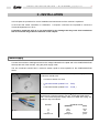
1
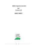
F1D Turbo • F3D • F4D • F5D • F9D • F12D --- Rev. FI 003 GB 8K2_3_14_16_17 v1.1
Electronic Metal Melting Machines
F1-D Turbo • F3-D • F4-D • F5-D
F9-D • F12-D
Operator’s manual
Serial number: ______________
Attention!
Operate the Unit referring to the Technical Booklet having the same serial number of the Machine.
Program Version: MFGC25xx MFG14xx
Rev.: FI 003 GB 8K2_3_14_16_17 v1.1
Date: 29 / 03 / 2007
1
2
F1D Turbo • F3D • F4D • F5D • F9D • F12D --- Rev. FI 003 GB 8K2_3_14_16_17 v1.1
INSTRUCTIONS
ATTENTION!
READ THESE INSTRUCTIONS CAREFULLY BEFORE WORKING WITH THE DEVICE
•
•
•
•
•
•
•
•
•
•
•
•
•
•
•
•
•
•
•
•
•
•
Read this booklet carefully before installing or operating the device and before carrying out maintenance operations. Keep this
booklet in a safe place, for future reference.
CEIA products may be operated with a high degree of safety provided that all the safety standards (following good sense and the
manufacturer's advice) are observed. It is therefore essential that the heads of staff safety make sure that all operators read this
manual before being allowed to use the device.
At all times during the installation, use and maintenance of the device follow the guidelines presented in this booklet. CEIA will not
be held responsible for any damage as a result of the device being used for purposed that are not expressly indicated in this
booklet.
Whenever there is the risk that the safety standards have been lowered, the device must be placed out of service in such a way that
as to render its accidental usage impossible and assistance must be requested.
The safety standards are to be considered lowered when:
- the device shows visual signs of deterioration;
- the device does not work correctly;
- the device has been stored in less than satisfactory conditions for a long period of time;
- the device has had to undergo severe strain during transportation;
- the device has come into contact with liquid substances.
The area directly surrounding the working zone must be supplied with adequate anti-incendiary devices.
All combustible materials must be removed from the working zone and placed at a safe distance.
Do not use excessive force during installation, use or maintenance of the device.
The operator must be able to access the controls of the device easily, without running personal risks.
Before providing the device with electrical power, check that the voltage from the power mains corresponds to the voltage shown on
the device's electrical specifications plaque.
Only connect the device to the power mains after having made all the connections needed for its complete installation.
The electrical plug must only be inserted into a socket containing a grounding contact. Any interruption in the protective conductor
either inside or outside the device, or the detaching of the protective grounding terminal, renders the device dangerous. Intentional
interruption is forbidden.
After melting, ensure that the metal that has been worked upon is allowed sufficient time to cool before handling it or bringing it into
contact with combustible material.
All electrical shocks are potentially fatal. Never touch parts charged with mains power. Keep clothes and body dry and never work in
wet environments. Whenever one becomes aware that the device or part of it has accidentally become electrically charged,
immediately stop the soldering operations and do not use the device until the problem has been located and resolved by qualified
personnel.
Wearers of electronic devices, such as pacemakers, must consult a doctor before coming into close contact with the device in order
to ascertain whether the magnetic fields produced by high currents may influence the functioning of the pacemaker.
Always remove the plug by hand when disconnecting the power supply cable, never by pulling on the cable.
To prevent damage by lightening, disconnect the power supply cable during thunderstorms.
Do not wash the device with water, liquid detergents or chemical substances. Use a slightly moist, non-abrasive cloth for cleaning.
Never cut off the safety features of the device.
Before any maintenance, cleaning or movement, the device must first be disconnected from all sources of power.
Carefully read the "Maintenance" chapter of this booklet before contacting your service centre. In the event of a problem, only
technicians that are specialized and authorized to work on CEIA machinery should be contacted.
Any malfunctioning parts must be replaced with parts specifically designed for the device.
It is important, as much as possible, to avoid carrying out maintenance or repairs on the device while it is open and supplied with
electrical power; if absolutely essential, such work must be carried out only by qualified personnel who are well aware of the risks
that are involved.
The capacitors within the device may remain charged even after the device has been disconnected from all sources of power. Wait
60 seconds before beginning repair work on the device.
Symbols
The device is marked with this symbol whenever the operator or the maintenance personnel, in order to avoid possible
damage, have to refer to the present manual.
The same symbol appears in the booklet at points where warnings or particularly important instructions are given instructions that are vital to a safe and correct use of the device
The device is marked with this symbol in those areas where a dangerous amount of voltage is present.
Only specialized maintenance personnel should make adjustments in these areas.
WARRANTY TERMS
The Warranty on all CEIA equipment relates to goods delivered from our factory, under our general and
specific conditions of sale.
F1D Turbo • F3D • F4D • F5D • F9D • F12D --- Rev. FI 003 GB 8K2_3_14_16_17 v1.1
3
CONTENTS
Page
INSTRUCTIONS ..............................................................................................................................................................2
SYMBOLS .........................................................................................................................................................................2
WARRANTY TERMS .....................................................................................................................................................2
I - DESCRIPTION............................................................................................................................................................4
WORKING DIAGRAM AND DESCRIPTION ....................................................................................................................4
Crucibles .....................................................................................................................................................................6
TECHNICAL CHARACTERISTICS OF MELTING MACHINES F1-D-TURBO, F3-D, F4-D, F5-D, F9-D, F12-D............7
II - INSTALLATION .......................................................................................................................................................9
POWER SUPPLY..............................................................................................................................................................9
COOLING ......................................................................................................................................................................10
GAS TORCH ..................................................................................................................................................................10
Gas torch orientation ...............................................................................................................................................11
Air intake ferrule adjustment ....................................................................................................................................12
Checking correct adjustment of the gas torch on machines with optical temperature reader..................................12
Use of an auxiliary gas torch....................................................................................................................................12
METAL TEMPERATURE SENSOR ................................................................................................................................13
Thermocouple ...........................................................................................................................................................13
Dual-wavelength Optical Sensor ..............................................................................................................................13
III - INSTRUCTIONS FOR USE ..................................................................................................................................14
WORK CYCLE ..............................................................................................................................................................15
Halting processing ....................................................................................................................................................17
IV - MAINTENANCE ....................................................................................................................................................18
INSTRUCTIONS FOR PERIODIC MAINTENANCE ........................................................................................................18
Melting unit - Crucible..............................................................................................................................................18
Hydraulic unit ...........................................................................................................................................................19
Water filter............................................................................................................................................................................... 19
Closed-circuit system (MTA cooler)........................................................................................................................................ 19
Optical temperature sensor.......................................................................................................................................20
Procedure for checking the aim of the optical sensor............................................................................................................... 20
Instructions for replacing a thermocouple................................................................................................................21
FAULT SIGNALS ...........................................................................................................................................................23
Voice messages .........................................................................................................................................................23
Fault signalling on SELECTED TEMPERATURE display.......................................................................................23
Selection of voice message language ........................................................................................................................24
Entering the TCS700 optical sensor coefficient........................................................................................................25
V – LIST OF PARTS......................................................................................................................................................26
SPARE PARTS ...............................................................................................................................................................26
OPTIONS .......................................................................................................................................................................26
ACCESSORIES ..............................................................................................................................................................26
CONSUMABLES............................................................................................................................................................26
DECLARATION OF CONFORMITY CE ..................................................................................................................27
CEIA S.p.A. reserves the right to make changes, at any time and without prior notice, to models (including
programming), to accessories and optional features, and to prices and conditions of sale.
4
F1D Turbo • F3D • F4D • F5D • F9D • F12D --- Rev. FI 003 GB 8K2_3_14_16_17 v1.1
I - DESCRIPTION
Working diagram and description
The working diagram of the Electronic Melting Machine is shown in Fig. I-1. The following sections are
illustrated:
1)
Control panel: this is located on the front of the device, and allows the operator to select the amount of
power delivered and the operating temperature.
2)
Medium-frequency generator: transforms the power supply voltage into medium-frequency energy,
which drives the coil. The amount of energy supplied to the coil can be adjusted.
3)
Coil: transforms the medium-frequency energy, provided by the medium-frequency generator, into a
variable magnetic field.
4)
Crucible: contains the metal to be melted; the crucible is heated by currents induced therein by the
magnetic field generated by the coil. In order to obtain an efficient transfer of energy, the crucible is
placed within the coil.
2
4
400V 3˜
(220V 3˜)
MEDIUMFREQUENCY
GENERATOR
1
Temperature
sensor
CONTROL PANEL
Power adjustment
Temperature adjustment
Melting On/Off
3
Fig. I-1 Melting machine block diagram
Control of the apparatus is entrusted to a microcomputer, which accepts instructions from the operator
(switching on and off, adjustment of the power delivered and selection of melting temperature), checks that
the machine is working correctly by means of a self-diagnostic device, and uses voice synthesis to give
information about the melting of the metal and any action necessary on the part of the operator
The power delivered, which depends on the temperature to be reached and the mass of the metal to be
melted, can be adjusted digitally by the operator.
The machine is also equipped with a thermoregulator with a pyrometer, via which the temperature the
metal must reach during the melting phase can be set.
The temperature sensor can be a dual-wavelength optical reader or an immersion thermocouple (for
measurement ranges see the “Technical Characteristics” section).
In addition to the power supply, the machine requires a water supply for the cooling system for the
electronic power devices inside, connections for which are made on the left side of the machine
The cooling water supply is monitored by a flowswitch, which prevents the machine from operating in the
case of supply failure or low water flow-rate.
The water temperature is controlled by a thermostat which blocks operation of the machine if overheating
occurs.
Figures I-2 and I-3 illustrate the electronic melting machines described in this manual.
5
F1D Turbo • F3D • F4D • F5D • F9D • F12D --- Rev. FI 003 GB 8K2_3_14_16_17 v1.1
SoP
So
CP
So
CG
CP
CR
SoP
CG
CR
PC
PC
CA
TG
TG
CA
MO
Fig. I-2 models F1-D Turbo , F3-D and F4-D with
optical temperature sensor (optional)
H2O OUT
PL
Fig. I-3 models F5-D, F9-D and F12-D with optical
temperature sensor (optional)
CR
MR
RP
S
Ti
H2O IN
Fig. I-4a cooling water inlets and
outlets.
CA
CG
CP
CR
H2O IN
H2O OUT
S
MO
power supply cable
gas torch
crucible lid
crucible
water inlet
water outlet
coil
container unit
Fig. I-4b detail of the melting unit
MR
PC
PL
RP
So
SoP
Ti
TG
Fig. I-4c detail of the immersion
thermocouple
refractory brick
control panel
crucible tongs
refractory plate
optic temperature sensor (optional)
support of the optic temperature sensor
immersion thermocouple (optional)
label
6
F1D Turbo • F3D • F4D • F5D • F9D • F12D --- Rev. FI 003 GB 8K2_3_14_16_17 v1.1
fig. I-5 detail of the plaque, with the details of an F9-D melting machine.
Crucibles
The machines are supplied with graphite or silicon-graphite crucibles selected to provide optimum
performance in terms of power delivered and melting quality. Their characteristics are set out below.
In order to obtain the best possible results, we strongly recommend that only approved crucibles be used
with CEIA melting machines.
d
b
c
f
a
g
)
A
B
e
Machine
model
F1-D
F3-D
F4-D
F5-D
F9-D
F9-D
Crucible
model
C1/G1
C3/G1
C4/G1
C5/G1
C9/G1
C9/S1
Code
Type
Capacity
a
b
c
d
e
f
g
21463
2316
19230
2314
2315
14764
60cc
161cc
350cc
500cc
800cc
800cc
30
42
60
70
80
80
85
117
124
138
160
160
56
80
98
118
128
128
98
138
140
154
176
176
50
70
88
112
116
116
48
68
92
100
100
82
118
122
146
168
168
F12-D
C12/G1
19611
graphite*
graphite*
graphite*
graphite*
graphite*
silicon-graphite
for high
temperatures**
graphite*
980cc
90
155
140
180
130
108
170
* recommended for operating temperatures up to 1200°C
** recommended for operating temperatures up to 1600°C
fig. I-6 available crucibles; A: crucible; B: refractory container
TABLE OF SPECIFIC
WEIGHTS OF SOME METALS
Al
2.56
Ag
10.53
Cd
8.60
Ni
8.40
Au
19.26
Pd
11.40
Cu
8.85
Rh
12.10
Zn
6.86
SPECIFIC WEIGHT AT DIFFERENT FINENESSES
Au
750‰
585‰
417‰
375‰
333‰
917‰
18KT
14KT
10KT
9KT
8KT
22KT
15.54
13.04
11.70
10.82
10.75
17.82
Ag
925‰
835‰
Ag.
Ag.
10.37
10.28
7
F1D Turbo • F3D • F4D • F5D • F9D • F12D --- Rev. FI 003 GB 8K2_3_14_16_17 v1.1
800‰
Ag.
10.20
Technical characteristics of melting machines F1-D-Turbo, F3-D, F4-D, F5-D, F9D, F12-D
Dimensions
(width x depth x height)
Machine
weight
Maximum
absorbed
power
Maximum
output
power
4,5 kVA
50 kVAR
63 kg
63 kg
F1-D-Turbo/220
1kg
Power supply
voltage
(three-phase
50/60 Hz)
200 - 240 V
F1-D-Turbo/400
1kg
360 - 440V
4,5 kVA
50 kVAR
F3-D/220
2,8kg
200 - 240 V
4,5 kVA
50 kVAR
F3-D/400
2,8kg
360 - 440V
4,5 kVA
50 kVAR
63 kg
F4-D/220
6kg
200 - 240 V
5,5 kVA
60 kVAR
63 kg
F4-D/400
6kg
360 - 440V
5,5 kVA
60 kVAR
63 kg
F5-D/220
8,6 kg
200 - 240 V
7 kVA
80 kVAR
133 kg
F5-D/400
8,6 kg
360 - 440V
7 kVA
80 kVAR
90 kg
F9-D/220
13,5 kg
200 - 240 V
9,5 kVA
95 kVAR
F9-D/400
13,5 kg
360 - 440V
9,5 kVA
95 kVAR
90 kg
F12-D/220
17 kg
200 - 240 V
12 kVA
115 kVAR
140 kg
F12-D/400
17 kg
360 - 440V
12 kVA
115 kVAR
90 kg
Operating
capacity in
pure gold
Model
430x450x905 mm
575x580x905 mm
63 kg
133 kg
Metal melting temperature:
selectable thanks to a digital thermoregulator and pyrometer with an
immersion thermocouple or an optical sensor (optional).
Measurement range:
- K-type thermocouple : 150÷1300 °C. *
- optical sensor: 700÷2000 °C.
* The maximum value should not be considered applicable for continuous
use. We recommend that operational temperatures should be at least 150°C
below these values.
Water cooling:
via a tank witha 0.5 Hp pump, or via a direct supply at the pressure indicated
in the table below:
intermittent working (50%)
tank
capacity
pump power
direct supply
pressure
flow
continuous working (<1300°C)
F1-D-Turbo • F3-D • F4-D
F5-D
F9-D
F12-D
200 l
0.5 Hp
300 l
0.5 Hp
300 l
0.5 Hp
500 l
0.5 Hp
200-600kPa
> 2 l/min
200-600kPa
> 22.5 l/min
200-600kPa
> 2.5 l/min
200-600kPa
> 2.5 l/min
500 l
0.5 Hp
750 l
0.5 Hp
750 l
0.5 Hp
1000 l
0.5 Hp
200-600kPa
> 2 l/min
200-600kPa
> 2.5 l/min
200-600kPa
> 2.5 l/min
200-600kPa
> 2.5 l/min
tank
capacity
pump power
direct supply
pressure
flow
Inlet: 3/4" screw fitting; Outlet: hose fitting, ø12mm
Safety features
Monitoring of thermocouple operation.
Monitoring of cooling-water temperature and flow.
Monitoring of all phases of the power supply.
8
F1D Turbo • F3D • F4D • F5D • F9D • F12D --- Rev. FI 003 GB 8K2_3_14_16_17 v1.1
Monitoring of the power supply voltage, for both excess and insufficient
voltage.
Special features
Very high efficiency: fast melting with the minimum energy consumption.
No generator maintenance required.
Consistent melting results thanks to microprocessor control.
Digital selection and control of the power and melting temperature.
Monitoring of wear on crucible.
Automatic cut-out if crucible is missing.
Self-diagnosis with messages by voice synthesis and display indication.
Accessories supplied
•
•
•
•
•
Options
Gas torch: useful to avoid metal oxidation during melting. Installed on the
induction melting machine plate, in order to let the flame spread on the
crucible.
Crucible
Crucible cover
Crucible tongs
Water circuit connection pipes: length 4 m.
TCS700-LPD Optical Temperature Sensor: this can replace a thermocouple
sensor, and has the following advantages:
• temperature measurement without contact
• no inertia, so allowing precision and reliability of reading
• no sensor maintenance
• no problem of metal contamination during melting caused by damage
to the thermocouple sheath
Sensor accuracy is not influenced by the metal state or type, nor by the
presence of smoke.
Immersion thermocouple
Measurement range:
- K-type thermocouple : 150÷1300 °C. *
* The maximum value should not be considered valid for continuous use. We
recommend that operational temperatures should be at least 150°C below
this value.
MTA 10 Cooling unit: Characterized by its compact dimensions and
equipped with digital regulating, it allows continuous operation for standard
melting (temperatures below 1300°C), maintaining the temperature of the
cooling water at the optimum level of 25°C.
Cooling capacity: 3.31 kW
MTA 20 Cooling unit: Characterized by its compact dimensions and
equipped with digital regulating, it allows continuous operation for standard
melting (temperatures below 1300°C), maintaining the temperature of the
cooling water at the optimum level of 25°C.
Cooling capacity: 6.94 kW
9
F1D Turbo • F3D • F4D • F5D • F9D • F12D --- Rev. FI 003 GB 8K2_3_14_16_17 v1.1
II - INSTALLATION
In this chapter the procedure for correct installation and maintenance of the machine is explained.
In the event that further information or clarification is required, customers are requested to contact the
Technical Department of C.E.I.A.
It should be noted that C.E.I.A. is not responsible for any damage that may result from installations
that do not follow the guidelines laid down in this chapter.
Power supply
Connect the machine to earth/ground and to the voltage indicated on the plate and in the CONFIGURATION
sheet (at the end of the manual), using the power supply cable.
The line conductors should have a minimum section equal to those specified in the CONFIGURATION
sheet:
For the standard model with 380-400V power supply the line
conductors should have:
•
a minimum section of 4 mm2
•
a 16A-rated socket (models F1-D ... F5-D)
or
a 32A-rated socket (models F9-D ... F12-D )
For the model with 208-230V power supply the line conductors
should have a minimum section of 6 mm2 and a 50A-rated socket.
N.B.: in this case the power supply cable is not fitted with a plug. The
conductor key is as follows:
Function
fig. II-1
L1
L2
L3
Earth/Ground
Conductor colour
(EUROPE)
(USA)
blue
brown
black
yellow/green
black
red
orange
green
10
F1D Turbo • F3D • F4D • F5D • F9D • F12D --- Rev. FI 003 GB 8K2_3_14_16_17 v1.1
Cooling
Feed "H2O IN" plant with water from from a water system or from a zinc-coated steel tank (see
Technical characteristics).
N.B. It is important to ensure that the temperature of the water entering the machine does not exceed 40° C.
The water-supply must be controlled, upstream, by a safety cock. If a tank is used (Fig. II-1) the pump will
take water from the bottom of the tank, while the water returning to the tank from the machine will be
deposited at the top of the tank.
Connect the water drain "H2O OUT"(Important: do not invert load and drain).
S
H2O OUT
R
fig. II-2
P
H2O IN
S: tank; R: water cock; P: pump
The liquid of the cooling unit must be water only, without additives, anti-freeze, anti-calcium agents, salts,
etc. In order to allow proper heat transfer from the water to the environment, do not use a tank in insulating
material (plastic, fiberglass, etc.).
Gas Torch
We recommend fitting the crucible with a gas torch which will prevent the metal oxidation and will lengthen
the life of the crucible. This accessory is fitted directly onto the melting machine work-surface, and orientated
so that the flame completely envelops the crucible opening.
fig. II-3
Upstream of the gas torch, install a valve to bring the pressure to 200÷300 kPa. Flame adjustment is made
by balancing the intake of air (using the Fs locking ring and Ra regulator) and the gas flow (using the Rg
tap).
F1D Turbo • F3D • F4D • F5D • F9D • F12D --- Rev. FI 003 GB 8K2_3_14_16_17 v1.1
11
2
Tg
Rg
Ra
Ug
Fs
Cg
1
fig. II-4a - Cg gas cannula; Rg gas tap; Fs
locking ring; Tg hose for inflow of gas; Ra air
adjuster; Ug nozzle
fig. II-4b - Nozzles included: 1: methane or
town gas nozzle; 2: propane gas nozzle
ATTENTION! The nozzle Ug of the gas torch must be changed depending on the gas used:
GAS
Propane
Methane or Town gas
ø nozzle
0.4mm
2,2mm
Gas torch orientation
The orientation must enable the flame to envelop the crucible mouth completely.
If the Melting Machine is fitted with an optical pyrometer, the gas torch must be positioned correctly and the
air flow properly adjusted, otherwise the pyrometer will measure the flame temperature rather than the metal
temperature during melting.
The figures below show the proper position of the gas torch: the flame must be aimed towards the rear rim of
the crucible and must create a whirl over the crucible mouth.
YES!
4
NO!
3
1
1
2
2
fig II-5:. 1: gas torch; 2: crucible; 3: air adjustment; 4: optical sensor.
12
F1D Turbo • F3D • F4D • F5D • F9D • F12D --- Rev. FI 003 GB 8K2_3_14_16_17 v1.1
Air intake ferrule adjustment
The locking ring 3 must be adjusted so as to obtain a blue flame as far as the rim of crucible and a yellowred one when over the crucible mouth.
Checking correct adjustment of the gas torch on machines with optical
temperature reader
• Turn the melting machine on at the main switch; place a crucible at room temperature in the melting
unit; do not start the melting process.
• Light the gas: if the position and the air adjustment are correct, the thermoregulator should indicate
---
a temperature below the measurement range ( display symbol
).
Use of an auxiliary gas torch
Do not use an auxiliary gas torch, as the pyrometer might read the gas temperature instead of the metal
temperature: always keep the torch on the same side as the optical sensor.
NO!
YES!
3
3
1
1
2
fig. II-6 . 1: gas torch; 2: crucible; 3: optical sensor.
2
13
F1D Turbo • F3D • F4D • F5D • F9D • F12D --- Rev. FI 003 GB 8K2_3_14_16_17 v1.1
Metal temperature sensor
Two types of temperature sensor can be installed on the electronic melting machine:
Thermocouple
Fix the two thermocouple supports St to the surface of the unit, on the right-hand side of the machine, using
the screws supplied.
Connect sensor cable C to the Ct connector on the side of the unit and rest the sensor on the supports.
C
Ti
Ct
St
fig. II-7 Ti: thermocouple; St: thermocouple supports; C: thermocouple cable ; Ct: sensor cable connector
Dual-wavelength Optical Sensor
Fix the tubular support SoP to the surface of the machine: the sensor So will point at the crucible's interior
automatically. Then connect the sensor cable to connector Ct.
C
c
C
SoP
So
SoP
fig. II-8 So: optical sensor; C optical sensor cable; Ct: optical sensor connector
DO NOT CHANGE the orientation of the sensor-cylinder So !
Ct
14
F1D Turbo • F3D • F4D • F5D • F9D • F12D --- Rev. FI 003 GB 8K2_3_14_16_17 v1.1
III - INSTRUCTIONS FOR USE
CEIA will not accept any responsibility for improper or negligent use, or
for use which does not comply with the rules laid down in this user’s
manual.
Before each melting operation
•
Crucible wear and tear
Before each melting operation the condition of the crucible should be checked: if there are areas that
have suffered damage the crucible should be replaced with a new one.
•
Noxious fumes
Additives and some alloys may produce noxious fumes during melting: all necessary measures should
therefore be taken to protect the health of the operator.
•
Additives
Do not put into the crucible compounds or materials which may produce phenomena harmful to
persons or property during operation and use of the melting machine. CEIA will not accept any
responsibility for improper or negligent use, or for use which does not comply with the rules
laid down in this user’s manual.
•
Crucibles
During the first melting operation, crucibles must be subjected to a gradual temperature increase, to
allow evaporation of any moisture which may have been absorbed. It is advisable to keep crucibles
near a source of heat to avoid the absorption of environmental humidity.
Check periodically, and always after moving the melting machine, that the coil is perfectly centred, in
order to avoid undue wear on the coating of the coil itself due to the friction of the crucible
•
Metal temperature
Do not overheat the metal to temperatures significantly above that of melting, so as to avoid splashing
of incandescent metal and the consequent risk of damage to persons or property. CEIA will not
accept any responsibility for improper or negligent use, or for use which does not comply with
the rules laid down in this user’s manual.
•
Cooling system
The cooling unit must be supplied with water only, without additives, anti-freeze, anti-calcium agents,
salts, etc.
•
Cooling system
If the melting machine cooling system is connected directly to a water mains outlet, the hydraulic unit
should be cleaned every six months (see Maintenance section)
•
Optical temperature sensor
During operation the lens of the sensor may become dirty due to dust or smoke: it should be cleaned
at least once a week.
The melting machine is equipped with a magnetothermal MAIN SWITCH, located on the control
panel. This switch serves as a protection against malfunctions.
F1D Turbo • F3D • F4D • F5D • F9D • F12D --- Rev. FI 003 GB 8K2_3_14_16_17 v1.1
15
Work Cycle
1
2
3
4
11
6
5
7
9
1
2
3
4
5
6
8
10
LED power indicator
Measured temperature
Indicator of power delivered
Selected temperature
Power decrease button
Power increase button
7
8
9
10
11
Selected temperature decrease button
Selected temperature increase button
Melting process Stop button
Melting process Start button
Main switch
fig. III-1 detail of the control panel
•
Supply the correct voltage (see values indicated on the plate attached to the rear of the unit) and water.
•
Turn on the MAIN SWITCH:
- the "LINE" indicator comes on
- the POWER display indicates the device’s software version (2-figure sequence)
- the SELECTED TEMPERATURE display indicates the selected melting temperature
•
When the melting machine is operative, the status of the indicators is as follows::
--on
--
1051
model with temperature
sensor
•
--model without temperature
sensor
Place the crucible in position. Absence of the crucible is noticed by the machine when the
button is
pressed; if this happens, the machine switches itself off and gives the message "Crucible missing".
Avoid melting when the crucible is very worn, as the crucible heats more slowly and the apparatus
might not reach its normal operational rating
)
The melting machine is delivered with the voice messages in the language indicated on the
CONFIGURATION sheet at the end of the manual. To activate a different language, follow the procedure
described in the MAINTENANCE section.
16
F1D Turbo • F3D • F4D • F5D • F9D • F12D --- Rev. FI 003 GB 8K2_3_14_16_17 v1.1
•
If the crucible is too worn, the message "Attention - replace crucible" is given a few seconds after the
machine is switched on; after this message, the machine will continue to work as long as there is no
immediate danger to the apparatus.
Here it must be noted that in continuing to use a worn-out crucible, one runs the risk of it breaking during
melting, which could cause serious injury to the operator or damage to the machine. CEIA will not accept
any responsibility for improper or negligent use, or for use which does not comply with the rules laid
down in this user’s manual.
•
Insert the metal into the crucible, taking care not to scratch the sides and calculating the quantity so that
during the melting stage it will remain a few centimetres below the rim of the crucible. This allows it to be
stirred using a graphite rod, and thus a constant fineness of product can be obtained.
•
Melting additives
For quicker, better melting, use additives such as boric acid; the resulting deposit can easily be removed
with a graphite rod when melting is completed.
•
(increase) and
Adjust the melting temperature using the
indication on the SELECTED TEMPERATURE display will change.
•
Press the
•
During melting, the POWER display shows the power delivered by the generator: the generator is
switched on and off automatically to keep the melting temperature constant. When the generator is off,
button (green) to start the melting process.
the display shows the message
)
(decrease) buttons: the
--
.
When the
button is pushed and during the heating phase, a short audible signal is emitted at
intervals of about 30” to indicated that the melting machine is in operation.
•
(increase) and
Adjust the power to the desired value using the
the POWER display indication with flash during adjustment.
•
Metal temperature control
Thermocouple
When metal is on the point of melting, start the temperature control by inserting the thermocouple into
the crucible. IMPORTANT: after insertion of the probe, the temperature sensor takes some time to reach
thermal equilibrium with the crucible; in this situation the pyrometer reading is not completely reliable and
the temperature of the crucible will not correspond exactly to that programmed. If one wants to be certain
of the working temperature of the metal, it is necessary to wait till the thermoregulator is stabilized: this is
indicated by the frequency with which the pyrometer is activated, which initially is of the order of every
few minutes, but when balance is reached is of the order of every few seconds.
(decrease) buttons:
When the immersion thermocouple reaches high temperatures or is subjected to sudden fluctuations in
temperature, it becomes mechanically weak: in this situation, handle the thermocouple with care, and avoid
impacts agaist the melting machine casing or other hard surfaces.
Optical temperature sensor
This is aimed at the crucible'sinterior. If a cover is necessary, remember that it darkens the crucible.
Due to the lack of inertia, the pyrometer will show a valid measurement of the metal's temperature when
the cover is taken off.
If the optical sensor malfunctions, refer to the notes in the “MAINTEANCE” section.
F1D Turbo • F3D • F4D • F5D • F9D • F12D --- Rev. FI 003 GB 8K2_3_14_16_17 v1.1
•
17
Gas torch
If a gas torch is used to avoid oxidation of the metal, keep the flame on the crucible for the entire
duration of the melting. It is advisable to use an auxiliary gas torch during the casting phase.
Before removing the crucible during melting, stop the machine by pressing the
button(red)
Halting processing
•
After use, turn off the MAIN SWITCH. Disconnect the mains supply.
Before closing the water cock or disconnecting the pump, wait till the crucible has completely cooled or take
the crucible out.
)
To prolong the life of crucibles, we recommend that it is removed from the machine when work is finished
and allowed to cool slowly with a cover on, in order to reduce thermic shock. It is a good idea to put in some
boric acid in this case, as the acid vaporizes during the cooling phase and, as it is in a closed container,
causes convection which helps to distribute it uniformly over the inside of the crucible.
18
F1D Turbo • F3D • F4D • F5D • F9D • F12D --- Rev. FI 003 GB 8K2_3_14_16_17 v1.1
IV - MAINTENANCE
Any maintenance or repair to the machine must only be carried out after
the power supply cable has been disconnected. CEIA will not accept any
responsibility for improper or negligent use, or for use which does not
comply with the rules laid down in this user’s manual.
Instructions for periodic maintenance
Melting unit - Crucible
It is very important to check the condition of the crucible before every melting operation. Here it must be
noted that in continuing to use a worn-out crucible, one runs the risk of it breaking during melting, which
could cause serious injury to the operator or damage to the machine. CEIA will not accept any
responsibility for improper or negligent use, or for use which does not comply with the rules laid
down in this user’s manual.
In the event that the melting device is under-powered (indication lower than 70% of maximum power), it is
recommended that the crucible be replaced (information given by the machine in the form of a voicesynthesized message).
To prolong the life of crucibles, we recommend that they are allowed to cool slowly with a cover on, in order
to reduce thermal shock. It is advisable to put in some boric acid in this case, as the acid vaporizes during
the cooling phase and, as it is in a closed container, causes convection, which helps to distribute it uniformly
over the inside of the crucible.
The parts that make up the melting unit are illustrated in Fig. IV-1. It is recommended that weekly checks are
made on the condition and correct positioning of these parts, and in particular of the condition of the coil
insulation.
CR
CP
MR
PL
RP
S
Fig. IV-1 Melting unit components
Rif.
RP
MR
CR
CP
PL
S
)
Description
Refractory plate
Refractory brick
Graphite crucible with refractory container
Refractory crucible cover
Tongs
Heating inductor
In order to obtain the best possible results, we strongly recommend that only approved crucibles be used
with CEIA melting machines.
F1D Turbo • F3D • F4D • F5D • F9D • F12D --- Rev. FI 003 GB 8K2_3_14_16_17 v1.1
19
Hydraulic unit
The liquid supplied to the cooling unit must be water only, without additives, anti-freeze, anti-calcium agents,
salts, etc . For closed-circuit systems, distilled water should be preferred.
To avoid periodic cleaning of the cooling system, we recommend that a closed-circuit system with
distilled water be used.
With the use of non-distilled water, the tubes of the hydraulic cooling unit are subject to the build-up of
calcium sediment. As a result, one or more sections of the tubes may become totally or partially blocked .
If this occurs, a partial block stops the water from flowing smoothly, causing overheating: the machine
control system interrupts the melting and signals a malfunctioning with a vocal message.
A total block stops the flow of water: again, the machine control system interrupts the melting and signals a
malfunctioning with a vocal message.
If blocking of the unit occurs, a complete check and manual cleaning of each component of the cooling unit
should be carried out (rubber tubing and power modules). It is advisable to disconnect one tube at a time, to
avoid the risk of mistakes in re-assembly
It is important that cleaning of the cooling unit be carried out with the machine switched off in order
to avoid the danger of injury to the operator
After the above operation, however, it is still advisable to carry out the periodic cleaning.
It is recommended that cyclical cleaning be carried out every six months. The cleaning operation is
carried out by means of a series of washes of the unit with a solution of water and solvay soda and
continues until the tubes are completely clean.
Water filter
The water intakes " H2O IN " are equipped with a filter net to ensure that any impurities in the water do not
get into the cooling system and impede the flow. Check regularly that this filter is not blocked.
Fig. IV-2a Detail of the water inlet
fitting
Fig. IV-2b Water inlet fitting components
Taking out the filter
Closed-circuit system (MTA cooler)
The system does not need any maintenance apart from periodic topping-up of the liquid.
N.B.: Use only distilled water for topping up! If distilled water is not used, the instructions in the section
above should be followed.
20
F1D Turbo • F3D • F4D • F5D • F9D • F12D --- Rev. FI 003 GB 8K2_3_14_16_17 v1.1
Optical temperature sensor
If the thermoregulator does not measure variations in the temperature during melting operations, or the
reading is erroneous, check that the sensor is aimed correctly and that the lens is clean. Also check that
the gas torch is not directed toward the sensor during use (see Installation section).
Clean the sensor lens periodically. The lens can be cleaned with a cotton-tipped stick dipped in alcohol. It is
advisable to carry out this cleaning every six months.
Procedure for checking the aim of the optical sensor
Switch the main switch to the ON position
Press the START button
----
Wait for the temperature read-out to exceed 800°C.
832
Or
=
18
BS
Press the START button for at least 5 seconds: the
message “Or =”
appears on the CRUCIBLE
TEMPERATURE display, whilst the SELECTED
TEMPERATURE display shows a number which
updates every second.
Loosen the sensor locking screw BS and find the
position which gives the maximum reading on the
SELECTED TEMPERATURE display. This figure
should generally be > 15.
Lock the sensor again.
Press the STOP button to return to normal operation.
Fig. IV-3
F1D Turbo • F3D • F4D • F5D • F9D • F12D --- Rev. FI 003 GB 8K2_3_14_16_17 v1.1
21
Instructions for replacing a thermocouple
If the sensor fails, the thermoregulator stops the machine in order to save the metal being treated. The digital
temperature controller will show an error message.
The thermocouple may stop functioning for one of two reasons:
1) The stainless steel protective sheath for the conductors in Cr-Al has become worn.
2) The working temperature has gone beyond the maximum limit of 1300°C causing fusion of the
above-mentioned components.
Correct operation of the thermocouple can be verified by checking the thermocouple terminals after having
removed it from the machine.
The Ohm value displayed by the multimeter (a scale
of Ohm x 10) must be close to zero, which indicates
uninterrupted operation. (To access the terminals see
step 2 of the procedure given below).
Another check is to verify that the external sheath is
insulated from one of the thermocouple terminals
(once again by using the multimeter); that is to say,
the tube in stainless steel must be insulated from the
head in Cr-Al. In this case the resistance must be
above 10 MOhm.
Should the test results not correspond to the abovementioned values, the thermocouple must be
replaced. To do so follow the procedure given below.
1)
Unscrew the locking ringlet A, which frees the
external protective sheath B from the
thermocouple. Unscrew the joint C.
2) Remove the screws E which seal the outside
cover D.
Fig. IV-4a
22
F1D Turbo • F3D • F4D • F5D • F9D • F12D --- Rev. FI 003 GB 8K2_3_14_16_17 v1.1
3)
Remove the fixing screws G for the ceramic
terminal-support H and loosen the terminalsupport in such a way that it can be rotated.
Free connecting cable J by loosening screws F
and ring nut K and then remove this cable. The
correspondence between the conductors and
the terminals is shown below:
green conductor (v) - red terminal(r)
red conductor (r) - yellow terminal(g)
4) Rotate the square joint L anti-clockwise until it
can be removed from the support tube.
5) Bend the rear of the thermocouple M into a wide
curve and carefully remove the square joint L.
6) Straighten the sheath M and pull it out of the
support tube.
7) Insert the new thermocouple M, with its ceramic
support H into the support tube and reassemble
by following the above-mentioned procedure in
reverse.
Fig. IV-4b
F1D Turbo • F3D • F4D • F5D • F9D • F12D --- Rev. FI 003 GB 8K2_3_14_16_17 v1.1
23
Fault signals
Voice messages
The melting machine is fitted with an effective system of self-diagnosis which notifies the operator when
some parts of the apparatus malfunction. Messages relating to this self-diagnosis are as follows:
" Attention - water
temperature too high"
" Attention - insufficient water
pressure"
" Attention - one phase
missing"
" Attention, crucible missing"
" Attention - replace crucible "
“ Attention – high voltage”
“ Attention – interrupted
thermocouple”
“ Attention – internal fault”
This is a continuous check. The machine turns itself off and will not
accept further instructions until the situation changes (T < 65°C).
This is a continuous check. The machine turns itself off and will not
accept further instructions until the situation changes. Check that the
water flow corresponds to that shown in the “Technical
Characteristics” section.
The message is also given when the tubing is obstructed by calcium
deposits - in this case the water cooling system must be cleaned.
This is a continuous check, and warns the operator that the three-phase
power circuit is unbalanced and will therefore not allow the machine to
work properly. The machine will not accept instructions until the situation
returns to normal.
is
Absence of the crucible is noticed by the machine when button
presed; if this happens, the machine switches itself off and gives the
message.
If the crucible is too worn, the message is given a few seconds after the
machine is switched on; after this message, the machine will continue to
operate as long as there is no immediate danger to the apparatus. Here
it must be noted that in continuing to use a worn-out crucible, one runs
the risk of it breaking during melting, which could cause serious
injury to the operator or damage to the machine. CEIA will not accept
any responsibility for improper or negligent use, or for use which
does not comply with this warning.
This is a continuous check. The machine turns itself off and will not
accept further instructions until the correct voltage supply resumes.
Check the thermocouple and replace if necessary. If the spare part is
not immediately available,disconnect the thermocouple cable from
connector Ct on the side of the casing.
Contact CEIA technical service personnel.
Fault signalling on SELECTED TEMPERATURE display
Fault code
Er1
Er2
Er3
Cause
Crucible missing
Internal fault
Insufficient water flow
Er4
Er5
Internal fault
High water temperature
Er6
Er7
Er8
Er9
One phase missing
interrupted thermocouple
Low voltage
High voltage
Action
Put the crucible in.
Contact CEIA technical service personnel.
• Check the water supply outlet
• Check the H2O IN filter
Contact CEIA technical service personnel.
Check the temperature of the water entering the
machine
Check power supply connections
Check the thermocouple and replace if necessary.
Check the power supply voltage
Check the power supply voltage
If the machine malfunctions without giving a diagnostic message, please contact C.E.I.A.
24
F1D Turbo • F3D • F4D • F5D • F9D • F12D --- Rev. FI 003 GB 8K2_3_14_16_17 v1.1
Selection of voice message language
1. To enter programming, switch the MAIN
SWITCH to ON while holding down the P key.
+
+
L9
=
1
1. The code of the Lg (language) parameter
appears on the CRUCIBLE TEMPERATURE
display, while the number of the currentlyselected language appears on the SELECTED
TEMPERATURE display.
2. Press key E to enter modification phase: the
number on the SELECTED TEMPERATURE
display will begin to flash.
2. Modify the value of the setting using the power
2
adjustment keys
1
2
3
4
5
6
+ and -, according to the table:
Italiano
English
Français
Deutsch
Español
Turkish
5. Press key E (or P) to leave the parameter
modification phase: the number on the SELECTED
TEMPERATURE display will stop flashing.
6. Press key P to exit programming.
Fig. IV-5
F1D Turbo • F3D • F4D • F5D • F9D • F12D --- Rev. FI 003 GB 8K2_3_14_16_17 v1.1
25
Entering the TCS700 optical sensor coefficient
Every TCS700 optical sensor has a numerical coefficient which determines its accuracy of measurement.
If an optical sensor is replaced, or fited to a melting machine as an upgrade kit, this coefficient must be
assigned to the OC operating parameter.
1. To enter programming, switch the MAIN
SWITCH to ON while holding down the P key.
+
+
L9
=
1
OC
=
2. The code of the Lg (language) parameter
appears on the CRUCIBLE TEMPERATURE
display, while the number of the currentlyselected language appears on the SELECTED
TEMPERATURE display.
1. Press power adjustment keys
(decrease) until you get
command.
(increase) or
to the OC
1000
2. Press key E to enter modification phase: the
number on the SELECTED TEMPERATURE
display will begin to flash.
3. Modify the value of the setting using the power
997
adjustment keys
+ and -.
5. Press key E (or P) to leave the parameter
modification phase: the number on the
SELECTED TEMPERATURE display will stop
flashing.
6. Press key P to exit programming.
Fig. IV-6
26
F1D Turbo • F3D • F4D • F5D • F9D • F12D --- Rev. FI 003 GB 8K2_3_14_16_17 v1.1
V – LIST OF PARTS
Spare parts
Modell
F1-D
Turbo/
220
F1-D
Turbo /
400
F3-D/
220
F3-D/
400
F4-D/
220
F4-D/
400
F5-D/
220
F5-D/
400
F9-D/
220
F9-D/
400
F12-D/
220
F12-D/
400
Generator MFG-F3/220
Generator MFG-F3/400
Generator MFG-F4/220
Generator MFG-F4/400
Generator MFG-F5/220
Generator MFG-F9/400
Generator MFG-F12/400
Power module D
Control panel complete with
display card 00800SDP
Temperature sensor
connection card 00800SGN
Heating inductor
Main switch
Surface in refractory material
Brick in refractory material
Gas torch
Optical pyrometric sensor
Support arm for optical
sensor
Crucible cover
Crucible tongs
19505
19244
19247
19506
19244
19247
19505
19244
19247
19506
19244
19247
19507
19244
19247
19508
19244
19247
19509
19244
19248
19509
19244
19248
19510
19244
19248
19510
19244
19248
19609
19244
19248
19609
19244
19248
19243
19243
19243
19243
19243
19243
19243
19243
19243
19243
19243
19243
19596
19596
19116
19116
19127
19127
19128
19128
19129
19129
19608
19608
19249
19246
19249
19246
19249
19246
19592
19246
19592
19249
19592
19249
20219
20219
7775
7775
19193
19193
9849
9849
9835
9835
19617
19617
9876
9876
9876
9876
9876
9876
14960
14960
14960
14960
14960
14960
4045
4045
4045
4045
4045
4045
4047
4047
4047
4047
4047
4047
TCS700 TCS700 TCS700 TCS700 TCS700 TCS700 TCS700 TCS700 TCS700 TCS700 TCS700 TCS700
19250
19250
19250
19250
19250
19250
19250
19250
19250
19250
19250
19250
12078
12078
2176
12079
2176
12079
19889
14448
19889
14438
2177
12080
2177
12080
2177
12081
2177
12081
2177
19619
2177
19619
Options
K-type thermocouple
19241
Complete optical pyrometric sensor
TCS700-LPD
Accessories
Model
300 litre zinc-coated steel tank
with 0.37kW 230V˜ pump
500 litre zinc-coated steel tank
with 0.37kW 230V˜ pump
300 litre stainless-steel tank with
0.37kW 230V˜ pump
300 litre zinc-coated steel tank
with 0.37kW 400V˜ pump
500 litre zinc-coated steel tank
with 0.37kW 400V˜ pump
300 litre stainless-steel tank with
0.37kW 400V˜ pump
Cooler MTA10 220-240V 1˜
F1-D Turbo/ 220 • F3-D/ 220 • F4-D/ 220 F5- F1-D Turbo/
D/ 220 • F9-D/ 220 • F12-D/ 220
400
F3-D/ 400
F4-D/ 400
F5-D/ 400
300L-230
-
500L-230
-
300L-230AQ
-
-
300L-400
-
500L-400
-
300L-400AQ
Cooler MTA20 380-415V 3˜
F9-D/ 400
F12-D/ 400
-
6309
6309
6309
6309
6309
-
-
-
-
-
-
-
6308
Consumables
Model
F1-D Turbo / 220 •
F1-D Turbo / 400
F3-D/ 220
F3-D/ 400
F4-D/ 220
F4-D/ 400
F5-D/ 220
F5-D/ 400
F9-D/ 220
F9-D/ 400
F12-D/ 220
F12-D/ 400
Graphite crucible
21463 (C1/G1)
-
2316 (C3/G1)
2176
19230 (C4/G1)
19889
2314 (C5/G1)
2177
2315 (C9/G1)
14764 (C9/S1)
2177
19611(C12/G1)
2177
Silicon-Graphite crucible
Crucible cover
F1D Turbo • F3D • F4D • F5D • F9D • F12D --- Rev. FI 003 GB 8K2_3_14_16_17 v1.1
DECLARATION OF CONFORMITY CE
DECLARATION OF CONFORMITY CE
DECLARATION DE CONFORMITE CE KONFORMITÄTSERKLÄRUNG CE
DECLARACION DE CONFORMIDAD CE DICHIARAZIONE DI CONFORMITÁ CE
Manufacturer
Fabricant / Hersteller / Fabricante / Costruttore:
CEIA S.p.A.
Zona industriale Viciomaggio 54/G 52040
Viciomaggio - Arezzo - ITALY
Declares that the product
déclare que ce produit / erklärt, daß das Produkt / declara que el producto / dichiara che il prodotto:
Product name:
Nom du produit: / Produktname:
Nombre del producto: / Nome:
Model
Série / Serie
Serie / Modello:
F1-D-TURBO
F5-D
D
Melting machine
Fondeuse a moyenne fréquence / Schmelzofen
Fundidora electrónica de metales / Fonditrice ad induzione
F3-D
F9-D
F4-D
F12-
all model
tous modèles/ alle Modelle
todos los modelos/ tutti i modelli
conforms to the following Product Specifications
est conforme aux spécifications suivantes / folgenden Produktspezifikationen entspricht
es conforme a las siguientes especificaciones / è conforme alle seguenti specifiche di prodotto:
Safety / Sécurité / Sicherheit / Seguridad / Sicurezza:
EN 60204 - 1 (1997)
This product complies with the requirements of the Low Voltage
Directive 73/23/EEC and following modifications indicated in the
93/68/EEC Directive.
Le produit ci-dessus répond aux exigences de la Directive 73/23/CEE
et aux modifications suivantes mentionnées dans la Directive
93/68/CEE concernant la basse tensions.
Dieses
Produkt
entspricht
den
Anforderungen
an
Niederspannungsgeräte gemäß der Norm 73/23/EEC und
nachfolgender, in der Norm 93/68/EEC angegebener Änderungen.
El producto indicado cumple los requisitos de la Low Voltage
Directive 73/23/CEE y siguientes modificaciones indicadas en la
Directiva 93/68/EEC/.
Il prodotto è conforme alle norme della direttiva 73/23/EEC e
successive modifiche indicate nella direttiva 93/68/EEC sulla bassa
tensione.
EMC
EN 55011: Group 2 - Class A
EN 61000-4-2
EN 61000-4-3
EN 61000-4-6
ENV50204
EN 61000-4-4
This product complies with the requirements of the EMC Directive
89/336/EEC and following modifications indicated in the 92/31/EEC
and 93/68/EEC Directives.
Le produit ci-dessus répond aux exigences de la Directive
89/336/CEE et aux modifications suivantes mentionnées dans les
Directives 92/31/EEC et 93/68/CEE concernant les interférences
électromagnétiques.
Dieses Produkt entspricht den Anforderungen der EMC-Norm
89/336/EEC und nachfolgender in den Normen 92/31/EEC und
93/68/EEC angegebener Änderungen.
El producto indicado cumple los requisitos de la Directiva EMC
89/336/CEE y siguientes modificaciones indicadas en las Directivas
92/31/EEC y 93/68/EEC.
Il prodotto è conforme alle norme della direttiva EMC 89/336/EEC e
successive modifiche indicate nelle direttive 92/31/EEC e 93/68/EEC.
SpA
Arezzo, 2000-05-24
Person in charge Lab. EMC
Resp. Laboratoire EMC / Laborattaché EMC
Resp. Laboratorio EMC / Resp. Lab. EMC
Ing. E. Sorini
27
28
F1D Turbo • F3D • F4D • F5D • F9D • F12D --- Rev. FI 003 GB 8K2_3_14_16_17 v1.1